EP1208907B1 - Système de réaction à plusieurs étapes à injecteurs intercalés ainsi que son utilisation dans l'alkylation - Google Patents
Système de réaction à plusieurs étapes à injecteurs intercalés ainsi que son utilisation dans l'alkylation Download PDFInfo
- Publication number
- EP1208907B1 EP1208907B1 EP01204561A EP01204561A EP1208907B1 EP 1208907 B1 EP1208907 B1 EP 1208907B1 EP 01204561 A EP01204561 A EP 01204561A EP 01204561 A EP01204561 A EP 01204561A EP 1208907 B1 EP1208907 B1 EP 1208907B1
- Authority
- EP
- European Patent Office
- Prior art keywords
- mixing zone
- reactor
- zone
- catalyst
- alkylation
- Prior art date
- Legal status (The legal status is an assumption and is not a legal conclusion. Google has not performed a legal analysis and makes no representation as to the accuracy of the status listed.)
- Expired - Lifetime
Links
Images


Classifications
-
- B—PERFORMING OPERATIONS; TRANSPORTING
- B01—PHYSICAL OR CHEMICAL PROCESSES OR APPARATUS IN GENERAL
- B01J—CHEMICAL OR PHYSICAL PROCESSES, e.g. CATALYSIS OR COLLOID CHEMISTRY; THEIR RELEVANT APPARATUS
- B01J8/00—Chemical or physical processes in general, conducted in the presence of fluids and solid particles; Apparatus for such processes
- B01J8/02—Chemical or physical processes in general, conducted in the presence of fluids and solid particles; Apparatus for such processes with stationary particles, e.g. in fixed beds
- B01J8/04—Chemical or physical processes in general, conducted in the presence of fluids and solid particles; Apparatus for such processes with stationary particles, e.g. in fixed beds the fluid passing successively through two or more beds
- B01J8/0496—Heating or cooling the reactor
-
- B—PERFORMING OPERATIONS; TRANSPORTING
- B01—PHYSICAL OR CHEMICAL PROCESSES OR APPARATUS IN GENERAL
- B01J—CHEMICAL OR PHYSICAL PROCESSES, e.g. CATALYSIS OR COLLOID CHEMISTRY; THEIR RELEVANT APPARATUS
- B01J8/00—Chemical or physical processes in general, conducted in the presence of fluids and solid particles; Apparatus for such processes
- B01J8/02—Chemical or physical processes in general, conducted in the presence of fluids and solid particles; Apparatus for such processes with stationary particles, e.g. in fixed beds
- B01J8/04—Chemical or physical processes in general, conducted in the presence of fluids and solid particles; Apparatus for such processes with stationary particles, e.g. in fixed beds the fluid passing successively through two or more beds
- B01J8/0446—Chemical or physical processes in general, conducted in the presence of fluids and solid particles; Apparatus for such processes with stationary particles, e.g. in fixed beds the fluid passing successively through two or more beds the flow within the beds being predominantly vertical
- B01J8/0449—Chemical or physical processes in general, conducted in the presence of fluids and solid particles; Apparatus for such processes with stationary particles, e.g. in fixed beds the fluid passing successively through two or more beds the flow within the beds being predominantly vertical in two or more cylindrical beds
- B01J8/0453—Chemical or physical processes in general, conducted in the presence of fluids and solid particles; Apparatus for such processes with stationary particles, e.g. in fixed beds the fluid passing successively through two or more beds the flow within the beds being predominantly vertical in two or more cylindrical beds the beds being superimposed one above the other
-
- B—PERFORMING OPERATIONS; TRANSPORTING
- B01—PHYSICAL OR CHEMICAL PROCESSES OR APPARATUS IN GENERAL
- B01J—CHEMICAL OR PHYSICAL PROCESSES, e.g. CATALYSIS OR COLLOID CHEMISTRY; THEIR RELEVANT APPARATUS
- B01J8/00—Chemical or physical processes in general, conducted in the presence of fluids and solid particles; Apparatus for such processes
- B01J8/02—Chemical or physical processes in general, conducted in the presence of fluids and solid particles; Apparatus for such processes with stationary particles, e.g. in fixed beds
- B01J8/04—Chemical or physical processes in general, conducted in the presence of fluids and solid particles; Apparatus for such processes with stationary particles, e.g. in fixed beds the fluid passing successively through two or more beds
- B01J8/0446—Chemical or physical processes in general, conducted in the presence of fluids and solid particles; Apparatus for such processes with stationary particles, e.g. in fixed beds the fluid passing successively through two or more beds the flow within the beds being predominantly vertical
- B01J8/0449—Chemical or physical processes in general, conducted in the presence of fluids and solid particles; Apparatus for such processes with stationary particles, e.g. in fixed beds the fluid passing successively through two or more beds the flow within the beds being predominantly vertical in two or more cylindrical beds
- B01J8/0457—Chemical or physical processes in general, conducted in the presence of fluids and solid particles; Apparatus for such processes with stationary particles, e.g. in fixed beds the fluid passing successively through two or more beds the flow within the beds being predominantly vertical in two or more cylindrical beds the beds being placed in separate reactors
-
- B—PERFORMING OPERATIONS; TRANSPORTING
- B01—PHYSICAL OR CHEMICAL PROCESSES OR APPARATUS IN GENERAL
- B01J—CHEMICAL OR PHYSICAL PROCESSES, e.g. CATALYSIS OR COLLOID CHEMISTRY; THEIR RELEVANT APPARATUS
- B01J8/00—Chemical or physical processes in general, conducted in the presence of fluids and solid particles; Apparatus for such processes
- B01J8/02—Chemical or physical processes in general, conducted in the presence of fluids and solid particles; Apparatus for such processes with stationary particles, e.g. in fixed beds
- B01J8/04—Chemical or physical processes in general, conducted in the presence of fluids and solid particles; Apparatus for such processes with stationary particles, e.g. in fixed beds the fluid passing successively through two or more beds
- B01J8/0492—Feeding reactive fluids
-
- C—CHEMISTRY; METALLURGY
- C07—ORGANIC CHEMISTRY
- C07C—ACYCLIC OR CARBOCYCLIC COMPOUNDS
- C07C2/00—Preparation of hydrocarbons from hydrocarbons containing a smaller number of carbon atoms
- C07C2/54—Preparation of hydrocarbons from hydrocarbons containing a smaller number of carbon atoms by addition of unsaturated hydrocarbons to saturated hydrocarbons or to hydrocarbons containing a six-membered aromatic ring with no unsaturation outside the aromatic ring
- C07C2/64—Addition to a carbon atom of a six-membered aromatic ring
- C07C2/66—Catalytic processes
-
- Y—GENERAL TAGGING OF NEW TECHNOLOGICAL DEVELOPMENTS; GENERAL TAGGING OF CROSS-SECTIONAL TECHNOLOGIES SPANNING OVER SEVERAL SECTIONS OF THE IPC; TECHNICAL SUBJECTS COVERED BY FORMER USPC CROSS-REFERENCE ART COLLECTIONS [XRACs] AND DIGESTS
- Y10—TECHNICAL SUBJECTS COVERED BY FORMER USPC
- Y10S—TECHNICAL SUBJECTS COVERED BY FORMER USPC CROSS-REFERENCE ART COLLECTIONS [XRACs] AND DIGESTS
- Y10S585/00—Chemistry of hydrocarbon compounds
- Y10S585/919—Apparatus considerations
- Y10S585/921—Apparatus considerations using recited apparatus structure
- Y10S585/922—Reactor fluid manipulating device
Definitions
- This invention relates to a multistage hydrocarbon treatment process with interstage injection of a quenching fluid and more particularly to vapor phase alkylation of an aromatic substrate with an alkylating agent with interstage injection of a quenching fluid comprising at least one of the aromatic alkylating agent and the aromatic substrate.
- Hydrocarbon treatment processes in which a hydrocarbon reaction component is reacted with a second reaction component which may be a hydrocarbon or a non-hydrocarbon are well known in the chemical processing industry.
- An important aspect of such processes are aromatic conversion processes which are carried out over molecular sieve catalysts.
- aromatic conversion reactions include the alkylation of aromatic substrates such as benzene to produce alkyl aromatics such as ethylbenzene, ethyltoluene, cumene or higher aromatics and the transalkylation of polyalkyl benzenes to monoalkyl benzenes.
- an alkylation reactor which produces a mixture of mono- and poly- alkyl benzenes may be coupled through various separation stages to a downstream transalkylation reactor.
- Such alkylation and transalkylation conversion processes can be carried out in the liquid phase, in the vapor phase or under conditions in which both liquid and vapor phases are present.
- Alkylation and transalkylation reactions may occur simultaneously within a single reactor.
- various series-connected catalyst beds are employed in an alkylation reactor as described below, it is a conventional practice to employ interstage injection of the aromatic substrate between the catalyst beds in order to control the temperature of the adiabatic process, which tends to enhance transalkylation reactions within the alkylation reactor. Without having cooling, the by-product (xylene) yield is too high.
- the alkylation product within the reactor includes not only ethylbenzene but also polyethylbenzene, principally diethylbenzene with reduced amounts of triethylbenzene, as well as other alkylated aromatics such as cumene and butylbenzene.
- the interstage injection of the ethylene results not only further in alkylation reactions but also transalkylation reactions where, for example, benzene and diethylbenzene undergo transalkylation to produce ethylbenzene.
- a separate transalkylation reactor is connected downstream through a series of separation stages, it is the accepted practice to minimize polyalkylation within the alkylation reactor in order to facilitate the subsequent treatment and separation steps.
- vapor phase alkylation is found in U.S. Patent No. 4,107,224 to Dwyer.
- vapor phase ethylation of benzene over a zeolite catalyst is accomplished in a down flow reactor having four series-connected catalyst beds.
- the output from the reactor is passed to a separation system in which ethylbenzene product is recovered, with the recycle of polyethylbenzenes to the alkylation reactor where they undergo transalkylation reactions with benzene.
- the Dwyer catalysts are characterized in terms of those having a constraint index within the approximate range of 1-12 and include, with the constraint index in parenthesis, ZSM-5 (8.3), ZSM-11 (8.7), ZSM-12 (2), ZSM-35 (4.5), ZSM-38 (2), and similar materials.
- U.S. Patent No. 4,520,220 to Watson et al discloses the use of silicalite catalysts having an average crystal size of less than 8 microns and a silica/alumina ratio of at least about 200 in the ethylation of an aromatic substrate such as benzene or toluene to produce ethylbenzene or ethyltoluene, respectively.
- the alkylation procedure can be carried out in a multi-bed alkylation reactor at temperatures ranging from about 350°-500°C. and, more desirably, about 400°-475°C, with or without a steam co-feed.
- the reactor conditions in Watson et al are such as provide generally for vapor phase alkylation conditions.
- alkylation is carried out at temperatures generally in the range of 370°C to about 470°C. and pressures ranging from atmospheric up to about 25 atmospheres over a catalyst such as silicalite or ZSM-5.
- the catalysts are described as being moisture sensitive and care is taken to prevent the presence of moisture in the reaction zone.
- the alkylation/transalkylation reactor comprises four series-connected catalyst beds.
- Benzene and ethylene are introduced into the top of the reactor to the first catalyst bed coupled by recycle of a polyethylbenzene fraction to the top of the first catalyst bed as well as the interstage injection of polyethylbenzene and benzene at different points in the reactor.
- silicalite is employed as a catalyst in the alkylation of a monoalkylated substrate, toluene or ethylbenzene, in order to produce the corresponding dialkylbenzene, such as ethyltoluene or diethylbenzene.
- Butler et al is the ethylation of toluene to produce ethyltoluene under vapor phase conditions at temperatures ranging from 350°-500°C.
- the presence of ortho ethyltoluene in the reaction product is substantially less than the thermodynamic equilibrium amount at the vapor phase reaction conditions employed.
- U. S. Patent No. 5,847,255 to Ghosh et al discloses vapor phase alkylation with separate transalkylation in which the output from the transalkylation reactor is recycled to an intermediate separation zone.
- the Ghosh et al process employs a multi-stage alkylation reactor in which four or more series-connected catalyst beds are employed in a downflow vapor phase reactor. Both benzene and ethylene are applied to the inlet of the reactor along with interstage injection of ethylene and/or benzene between the catalyst stages.
- a benzene separation zone from which an ethylbenzene/polyethylbenzene fraction is recovered from the bottom with recycling of the overhead benzene fraction to the alkylation reactor, is preceded by a prefractionation zone.
- the prefractionation zone produces an overhead benzene fraction which is recycled along with the overheads from the benzene column and a bottom fraction which comprises benzene, ethylbenzene and polyethylbenzene.
- Two subsequent separation zones are interposed between the benzene separation zone and the transalkylation reactor to provide for recovery of ethylbenzene as the process product and a heavier residue fraction.
- the polyethylbenzene fraction from the last separation zone is applied to the transalkylation reactor and the output there is applied directly to the second benzene separation column or indirectly through a separator and then to the second benzene separation column.
- the ratio of benzene (or other aromatics substrate) and alkylating agent can be varied along the length of the reactor with the introduction of one or both reactants into the reactor at locations between catalyst beds. Any suitable technique can be employed to accomplish the interstage introduction of reactants into the reactor, but a typical system comprises a sparger, comprising a header which supplies feed stock into a plurality of sparger tubes within the header.
- U.S. Patent No. 3,728,249 to Antezana et al. discloses a process for the operation of a hydrogenation reaction in which a plurality of feedstocks are hydrotreated in a series of hydrotreating zones.
- One or more feedstocks may be employed, and an effluent from one reaction zone may be withdrawn from the first hydrotreating zone, cooled exteriorly of the hydrotreating reactor, and then returned to a zone between the first hydrotreating zone and a second hydrotreating zone where it may be mixed with a second feedstock.
- water may be introduced to zones separating the hydrotreating zones to effect a cooling action.
- a multistage hydrocarbon treatment process in a multistage reaction zone having a plurality of series-connected catalyst beds each containing a hydrocarbon reaction catalyst and spaced from one another to provide an intermediate mixing zone between adjacent catalyst beds.
- a processing feedstock containing a hydrocarbon substrate component comprising benzene or monoalkyl benzene and a normally gaseous-reacting C 2 -C 4 alkylating component for reaction with said substrate component to produce a reaction product is supplied to the inlet side of the reaction zone.
- the reaction zone is operated under temperature and pressure conditions in which the hydrocarbon substrate component is in the gas phase to cause a gas phase reaction of the components to produce the desired reaction product in the presence of the catalyst.
- a quench fluid comprising at least one of the hydrocarbon substrate component and the reactant component is injected into at least one intermediate mixing zone between adjacent catalyst beds.
- This quench fluid is dispensed into the interior of the mixing zone through a plurality of flow paths in which one portion of the flow paths is directed upwardly within the mixing zone and another portion directed downwardly within the mixing zone.
- the reaction product produced by the reaction of the hydrocarbon substrate component and the reactant component is recovered from a down-stream outlet of the reaction zone.
- a process for the vapor phase alkylation of an aromatic substrate comprising benzene or monoalkyl benzene in a multi-stage alkylation reactor employing intermediate mixing zones.
- a multi-stage reaction zone having a plurality of series-connected catalyst beds containing a molecular sieve aromatic alkylation catalyst. The catalyst beds are spaced from one another to provide mixing zones between adjacent catalyst beds.
- a feedstock containing the aromatic substrate and a C 2 -C 4 alkylating agent is supplied to an inlet side of the reaction zone.
- the reaction zone is operated at temperature and pressure conditions in which the aromatic substrate is in the gas phase and causing vapor phase alkylation of the aromatic substrate as the aromatic substrate and the alkylating agent flow through the reaction zone and pass from one catalyst bed to the next.
- a quench fluid comprising one or both of the aromatic substrate and the alkylating agent is supplied into the interior of the mixing zone through a plurality of flow paths. In the flow paths, one portion of the flow paths is directed upwardly within the mixing zone and another portion downwardly within the mixing zone. Alkylated product is then recovered from the downstream side of the reaction zone.
- the aromatic substrate is benzene and the alkylating agent is an ethylating agent such as ethylene.
- the quench fluid is supplied to the mixing zone through a plurality of dispersion channels which are spaced laterally from one another and extend transversely across the mixing chamber. At least some of the dispersion channels dispense the quench fluid alternately, upwardly and downwardly within the mixing zone. Preferably, the dispersion channels are located within the upper one-half of the mixing zone.
- a multi-stage alkylation reaction zone is provided within an elongated reactor having an upper catalyst bed extending transversely of the reactor and at least three subsequent catalyst beds extending transversely of the reactor and spaced from one another. Spacing between the catalyst beds provides an upper mixing zone between the first catalyst bed and the next adjacent catalyst bed and subsequent mixing zones between the succeeding catalyst beds.
- Sparger systems are provided in the mixing zones incorporating a plurality of laterally-spaced dispersion channels.
- a mixture of the aromatic substrate and the alkylating agent is supplied to the sparger systems to provide a plurality of flow paths through linearly-spaced orifice outlets in the dispersion channels directed upwardly and downwardly within the mixing zone.
- an alkylation reactor comprising an elongated reactor vessel having an inlet for the supply of reactants and an outlet for the withdrawal of product from the vessel.
- a plurality of catalyst beds are provided along the length of the reactor with a plurality of sparger systems each comprising a plurality of laterally displaced dispersion tubes and a manifold or header connecting the spaced dispersion tubes to provide for the supply of feedstock there too.
- At least some of the dispersion tubes have openings along the lengths thereof in which the openings alternately open in a downward and an upward orientation to dispense feedstock into the mixing zones.
- the present invention follows the accepted practice of carrying out vapor phase alkylation of an aromatic substrate such as benzene in a reactor involving a plurality of series-connected catalyst stages with a supplementary injection of a quenching fluid or aromatic substrate comprising benzene or monoalkyl benzene and C 2 -C 4 alkylating agent into mixing zones within the reactor interposed between reactor stages.
- a quenching fluid or aromatic substrate comprising benzene or monoalkyl benzene and C 2 -C 4 alkylating agent
- the interstage injection of the benzene or monoalkyl benzene and ethylene or other C 2 -C 4 alkylating agent is accomplished through the use of a unique sparging system in which the simultaneous flow of feedstock is directed both upwardly and downwardly within a mixing zone in a manner to enhance mixing of the reactants as they flow from one catalyst stage to the next.
- the invention may be applied to the reaction in the vapor phase alkylation of benzene or mono alkyl benzene with a C 2 -C 4 alkylating agent to produce, for example, ethylbenzene, ethyltoluene, cumene, or heavier alkylated aromatic compounds, the invention shall be described in this detailed description with respect to the ethylation of benzene.
- a preferred molecular sieve catalyst is silicalite, and the following detailed description of the invention will be made with respect to the use of a silicalite alkylation catalyst.
- Silicalite is a molecular sieve catalyst which is similar to the ZSM-5 zeolites but is typically characterized by a higher silica/alumina ratio providing an aluminum unit cell ratio of less than 1 and, in addition, is normally characterized as having a somewhat larger than average crystal size than is commonly associated with the ZSM zeolites.
- silicalite which in the as-synthesized form is characterized by orthorhombic symmetry, can be converted to monoclinic symmetry by a calcination procedure as disclosed, for example, in U.S. Patent No. 4,599,473 to Debras et al.
- silicalite typically has a relatively large crystal size.
- silica/alumina ratio of about 200
- silicalite is further characterized in terms of a variable aluminum gradient such that the aluminum gradient is positive when going from the interior to the surface of the molecular sieve crystal. That is, the silicalite can be characterized by a core portion which is relatively aluminum-deficient with an outer shell portion which is relatively aluminum-rich. It is to be understood that the term "aluminum-rich" is a relative term, and that for silicalite even the outer shell portion of the crystallite has a low aluminum content.
- the alkylation and transalkylation reactors are integrated with an intermediate recovery zone, preferably involving a plurality of separation zones operated in a manner to effectively provide feed streams to the reactors with recycle of the output from the transalkylation reactor to a benzene recovery zone downstream of the alkylation reactor.
- the transalkylation product is applied to an initial stage of a benzene recovery zone.
- Subsequent separation steps are carried out in a manner to apply a split feed to the transalkylation reactor.
- the alkylation reactor is a multistage reaction zone containing at least three, and preferably four or more, series-connected catalyst beds which contain the silicalite or other molecular sieve alkylation catalyst.
- the preferred silicalite alkylation catalyst preferably is silicalite characterized as having a high monoclinicity and a small sodium content.
- the preferred catalyst used in the transalkylation reactor is a molecular sieve having a pore size greater than the pore size of the silicalite catalyst.
- the transalkylation catalyst is zeolite Y.
- the alkylation reactor is preferably operated at substantially higher temperature conditions than the transalkylation reactor.
- One application of the invention is in a system involving a multistage alkylation reactor with the output coupled to a four-stage separation system which in turn supplies a polyethylbenzene feed to a transalkylation reactor.
- parallel alkylation and transalkylation reactors are employed. This results in a preferred mode of operation in which the parallel alkylation reactors are simultaneously operated in an alkylation mode while periodically one reactor can be taken off-stream with the feedstream completely supplied to the on-stream reactor.
- two parallel reactors are employed although it is to be recognized that three or more reactors can likewise be employed in parallel.
- a similar configuration is employed for the transalkylation reactors.
- the alkylation reactor comprises at least four catalyst beds as described above. More beds can be provided, and it will sometimes be advantageous to provide at least five catalyst beds in the alkylation reactor.
- the reactor is operated so as to provide vapor phase alkylation (both the aromatic substrate and the alkylating agent are in the vapor phase) at temperatures ranging from about 332°C - 427°C (630-800°F) at the inlet to about 371°C-454°C (700-850°F) at the outlet.
- the pressure may be within the range of about 17 to 31 bars (250 to 450 psia) with the pressure decreasing from one bed to the next as the temperature increases.
- the benzene and ethylene supplied to the top of the reactor may enter the reactor at a temperature of about 393°C (740°F) and a pressure of about 30bars (430 psia).
- the alkylation reaction is exothermic so that the temperature progressively increases from the first to the last catalyst bed by a way of example.
- the interstage temperatures may increase from 399°C (750°F) for the first catalyst bed to 407°C (765°F) after the second catalyst bed to 438°C (820°F) after the third catalyst bed to a temperature of about 449°C (840°F) after the last catalyst bed.
- a benzene-ethylene mixture is introduced to the first catalyst bed at the top of the reaction zone and also in intermediate mixing zones between the several successive stages of catalyst beds.
- ethylene is supplied along with benzene to the top of the first catalyst bed top at the upper end of the reactor.
- interstage injection of ethylene and benzene in a quench feed is provided for between some or all of the subsequent catalyst beds.
- the benzene to ethylene mole ratio is about 15-25 as injected into the top of the alkylation reactor and progressively decreases because of the interstage injection of ethylene along with reduced amounts of benzene and coupled with the alkylation of the benzene to ethylbenzene and polyethylbenzenes.
- the mole ratio of benzene to ethylene at the interstage injection points can vary from zero (no benzene injection) or about one up to about eight.
- the benzene can be employed in an amount less than the amount of ethylene on a mole basis. Stated otherwise, benzene can either not be injected between the catalyst beds or, if injected, can be employed in a relatively minor amount, i.e., a mole ratio of benzene to ethylene of less than one.
- the benzene/ethylene mole ratio can be as high as eight, and at mixing zones near the outlet end of the reactor only benzene may be injected. This is coupled with a somewhat lower operating temperature than would normally be the case for vapor phase alkylation.
- the temperature of the benzene stream into the top of the alkylation reactor can be in the order of 382°C (720°F) or lower.
- the alkylation reaction is, of course, an exothermic reaction so that the temperature will increase progressively throughout the alkylation column as noted previously.
- the silicalite alkylation catalyst employed in the present invention is a molecular sieve from the pentasil family of high silica molecular sieves.
- pentasil molecular sieves are described, for example, in Kokotailo et al, "Pentasil Family of High Silica Crystalline Materials," Chem. Soc. Special Publ. 33, 133-139 (1980).
- the silicalite molecular sieve alkylation catalyst has a somewhat smaller pore size than the preferred zeolite-Y employed in the transalkylation reactor.
- the silicalite catalyst has an effective pore size or window within the range of 0,0005 - 0,0006 microns (5-6 angströms).
- Zeolite Y has a pore size of about 0.0007 microns (7 angströms).
- the preferred silicalite catalyst has a somewhat smaller crystal size, less than one micron, than is usually the case.
- the crystal size is even somewhat smaller, about 0.5 microns as contrasted with a crystal size of perhaps 1-2 microns up to about 8 microns for similar catalysts such as disclosed in the aforementioned Patent No. 4,489,214 to Butler et al.
- a preferred silicalite for use in the present invention is extruded with an alumina binder in a "trilobe" shape having a nominal diameter of about 16 mm (1/16") and a length of the extrudate of about 32 - 64 mm (1/8-1/4").
- the "trilobe" cross-sectional shape is something of the order of a three-leaf clover. The purpose of this shape is to increase the surface area of the extruded catalyst beyond what one would expect with a normal cylindrical extrudate.
- the preferred silicalite catalyst is characterized as "monoclinic silicalite.” Monoclinic silicalite may be prepared as disclosed in U.S. Patent Nos.
- the catalysts will have near 100% monoclinicity although silicalite catalysts that are 70-80% monoclinic and about 20-30% orthorhombic symmetry may be used in the preferred embodiment of the invention.
- the silicalite preferably is present in an amount of 75-80 wt.% with the alumina binder being present in an amount of 20-25 wt.%.
- the silica/alumina ratio of the silicalite is at least 275 and preferably at least 300.
- An especially preferred silica/alumina ratio is 300-350, and silicalite within this range was used in experimental work respecting the invention as described hereafter.
- the silicalite may have an alpha value of about 20-30.
- the "alpha value” is characterized in terms of the activity of a catalyst for cracking hexane as disclosed in U.S. Patent Nos. 4,284,529 to Shihabi and 4,559,314 to Shihabi.
- the catalyst typically contains small amounts of sodium and iron.
- the silicalite alkylation catalyst has a crystal structure characterized by an aluminum-rich outer shell and an aluminum-deficient interior portion when compared with the outer shell.
- the silicalite catalyst is dry and has no appreciable or intended water content.
- the alumina binder is a high purity alumina such as "catapal alumina.”
- the silicalite catalyst preferably contains only a small amount of sodium, about 70-200 ppm sodium oxide, and contains only a small amount of iron oxide, about 300-600 ppm.
- the catalyst need not contain any additional "promoter" metals incorporated during the synthesis of the catalyst.
- a product stream comprising a mixture of ethylene and benzene in a mole ratio of benzene to ethylene about 10 to 20 is supplied via line 1 to an alkylation zone 2.
- Alkylation zone 2 comprises one or more multi-stage reactors having a plurality of series-connected catalyst beds containing the silicalite as described above or another suitable molecular sieve alkylation catalyst.
- the alkylation zone is operated at temperature and pressure conditions to maintain the alkylation reaction in the vapor phase, i.e. the aromatic substrate is in the vapor phase and preferably at a feed rate to provide a space velocity enhancing diethylbenzene production while retarding xylene production.
- the output from the alkylation reactor is supplied via line 3 to an intermediate recovery zone 4 which provides for the separation and recovery of ethylbenzene as a product.
- ethylbenzene is withdrawn from zone 4 via line 4a and applied for any suitable purposes such as in the production of vinylbenzene.
- Recovery zone 4 normally will be characterized by a plurality of series-connected distillation columns as described below and will result in a heavy polyalkylated product stream which is supplied via line 5 to a transalkylation zone 6.
- benzene will also be recovered from the intermediate recovery zone via a line 4b.
- the benzene may be applied as indicated by the broken lines both for recycle back to the alkylation reactor and also to the transalkylation zone as may be appropriate.
- the benzene and diethylbenzene undergo a disproportionation reaction resulting in a product of enhanced ethylbenzene content and diminished benzene and diethylbenzene content.
- the output from the transalkylation zone will be supplied via line 7 for recycle to the separation zone 4.
- FIG. 2 there is illustrated in greater detail a suitable system incorporating a multi-stage intermediate recovery zone for the separation and recycling of components involved in the alkylation/transalkylation process.
- an input feed stream is supplied by fresh ethylene through line 11 and fresh benzene through line 12.
- Line 12 is provided with a preheater 14 to heat the benzene stream to the desired temperature for the alkylation reaction.
- the feedstream is applied through a two-way, three-position valve 16 and inlet line 17 to the top of one or both parallel alkylation reaction zones 18 and 20 comprising a plurality of series connected catalyst beds each of which contains a molecular sieve alkylation catalyst.
- the reactors are operated at an average temperature, preferably within the range of 371°C - 427°C (700°F-800°F) and at pressure conditions of about 14 - 24 bars (200 to 350 psia), to maintain the benzene in the gaseous phase.
- valve 16 is configured so that the input stream in line 10 is roughly split to provide flow to both reactors in approximately equal amounts. Periodically, one reactor can be taken off-stream for regeneration of the catalyst. Valve 16 is configured so that all of the feedstream from line 10 can be supplied to reactor 18 while the catalyst beds in reactor 20 are regenerated and visa versa. The regeneration procedure will be described in detail below but normally will take place over a relatively short period of time relative to the operation of the reactor in parallel alkylation mode.
- this reactor When regeneration of the catalyst beds in reactor 20 is completed, this reactor can then be returned on-stream, and at an appropriate point, the reactor 18 can be taken off-stream for regeneration.
- the feedstream is supplied to each reactor to provide a space velocity of about 35 hr -1 LHSV .
- the space velocity for reactor 18 will approximately double to 70 hr -1 LHSV.
- reactor 20 When the regeneration of reactor 20 is completed, it is placed back on-stream, and again the flow rate space velocity for each reactor will decrease to 35 hr -1 until such point as reactor 18 is taken off-stream, in which the case the flow rate to reactor 20 will, of course, increase, resulting again in a transient space velocity in reactor 20 of 70 hr -1 LHSV.
- a preferred alkylation reactor 18 implementing the present invention through the use of sparger systems for the interstage injection of a quench fluid comprising usually mixtures of benzene and ethylene although either benzene or ethylene alone can also be employed in the quench fluid.
- the reactor 18 comprises an elongated reactive vessel 60 having an inlet 62 and an outlet 64. Benzene and ethylene are supplied to the reactor via inlet 62, and the alkylated product typically comprised of ethylbenzene and polyethylbenzenes along with unreacted benzene and ethylene is withdrawn via line 64.
- the reactor comprises a plurality of series-connected catalyst beds A, B, C, D and E.
- Each sparger system comprises a header tube or manifold 71 which extends transversely into the intermediate mixing zone as indicated in Fig. 3 and is shown in more detail in Fig. 4 described below.
- the header manifold supports a plurality of dispensing tubes 73, 74, 75, 76 and 77 which are spaced from one another in a generally horizontal or planar conformation.
- Each sparger system is supplied by ethylene through a supply line 78 and benzene through a supply line 79 through suitable proportioning valves as indicated to supply a quench fluid having the desired ratio of benzene and ethylene.
- the sparger system is configured to provide the quench fluid comprising a mixture of the aromatic substrate and/or the ethylene into the mixing zone through a plurality of flow paths in which some flow paths are directed upwardly within the mixing zone and other flow paths directed downwardly within the mixing zone.
- the sparger system incorporating the dispersion tubes is located in the mixing zone in relative proximity to the overlying catalyst bed in order to further enhance mixing of the benzene and ethylene within the mixing zone.
- the header tube and the corresponding diffusion tubes are located within the upper half of the vertical dimension of the mixing zone and preferably within the upper 1/4 of the mixing zone.
- the flow paths through which quenching fluids are dispensed are oriented at acute angles from the horizontal within the range of 30° to 60° upwardly and downwardly.
- the orifices are oriented at angles of about 45° from the horizontal of both upwardly and downwardly.
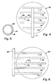
- FIG. 4 there is illustrated a preferred embodiment of the invention in which alternating upward and downward flow of the quenching fluid is accomplished through alternate orifices in a given dispersion tube. More specifically, Fig. 4 is a plan view of a sparger system incorporating a header tube 71 and dispersion tubes 73 through 77, with each dispersion tube equipped with alternating upwardly and downwardly oriented dispersion orifices. In Fig. 4, upwardly oriented orifices are indicated by solid lines and downwardly oriented orifices (which are masked when viewed from the top) are indicated by broken lines.
- orifices 80 are oriented in an upward direction and intervening orifices 81 are oriented in a downward direction. This sequential orientation of the alternating orifices is also shown in Fig. 4.
- the schematic offset sectional view of Fig. 5 shows orifice 80 oriented in an upward direction and orifice 81 oriented in a downward direction.
- FIG. 6 illustrates an alternative embodiment of the invention in which interference of the header tube with flow and mixing within the mixing zone is eliminated by placing the header manifold externally of the reactor.
- the sparger system incorporates a plurality of dispersion tubes 73-77 similarly as described above with reference to Figs. 3 and 4 and, in addition, an external manifolding system.
- the dispersion tubes extend through the wall of the reactor 60 where they are connected to manifold 84 which provides an external header.
- Manifold 84 is connected to ethylene and benzene supply lines similarly as described above with reference to Fig. 3.
- the mixing action of the alternating ports dispensing quench fluids from the dispersion tubes is maximized or enhanced since the header tube itself does not interfere with fluid flow through the mixing system.
- the effluent stream from one or both of the alkylation reactors 18 and 20 is supplied through a two-way, three-position outlet valve 24 and outlet line 25 to a two-stage benzene recovery zone which comprises as the first stage a prefractionation column 27.
- Column 27 is operated to provide a light overhead fraction including benzene which is supplied via line 28 to the input side of heater 14 where it is mixed with benzene in line 12 and then to the alkylation reactor input line 10.
- a heavier liquid fraction containing benzene, ethylbenzene and polyethylbenzene is supplied via line 30 to the second stage 32 of the benzene separation zone.
- Stages 27 and 32 may take the form of distillation columns of any suitable type, typically, columns having from about 20-60 trays.
- the overheads fraction from column 32 contains the remaining benzene which is recycled via line 34 to the alkylation reactor input. Thus, line 34 corresponds to the output line 4b of Fig. 1.
- the heavier bottoms fraction from column 32 is supplied via line 36 to a secondary separation zone 38 for the recovery of ethylbenzene.
- the overheads fraction from column 38 comprises relatively pure ethylbenzene which is supplied to storage or to any suitable product destination by way of line 40, corresponding generally to output line 4a of Fig. 1.
- the ethylbenzene may be used as a feedstream to a styrene plant in which styrene is produced by the dehydrogenation of ethylbenzene.
- the bottoms fraction containing polyethylbenzenes, heavier aromatics such as cumene and butylbenzene, and normally only a small amount of ethylbenzene is supplied through line 41 to a tertiary polyethylbenzene separation zone 42.
- line 41 is provided with a proportioning valve 43 which can be used to divert a portion of the bottoms fraction directly to the transalkylation reactor.
- the bottoms fraction of column 42 comprises a residue which can be withdrawn from the process via line 44 for further use in any suitable manner.
- the overhead fraction from column 42 comprises a polyalkylated aromatic component containing diethylbenzene and triethylbenzene (usually in relatively small quantities) and a minor amount of ethylbenzene is supplied to an on stream transalkylation reaction zone.
- parallel transalkylation reactors 45 and 46 are provided through inlet and outlet connections involving valves 47 and 48. Both of reactors 45 and 46 can be placed on stream at the same time so that both are in service in a parallel mode of operation.
- only one transalkylation reactor can be on-stream with the other undergoing regeneration operation in order to burn coke off the catalyst beds.
- the ethylbenzene content of the transalkylation feedstream can be kept small in order to drive the transalkylation reaction in the direction of ethylbenzene production.
- the polyethylbenzene fraction withdrawn overhead from column 42 is supplied through line 49 and mixed with benzene supplied via line 50. This mixture is then supplied to the on-line transalkylation reactor 45 via line 51.
- the benzene feed supplied via line 50 is of relatively low water content, about 0.05 wt.% or less.
- the water content is reduced to a level of about 0.02 wt.% or less and more preferably to no more than 0.01 wt.%.
- the transalkylation reactor is operated as described before in order to maintain the benzene and alkylated benzenes within the transalkylation reactor in the liquid phase.
- the alkylation reactor and the transalkylation reactor may be operated to provide an average temperature within the transalkylation reactor of about 66°C - 288 °C (150°F-550°F) and an average pressure of about 41 bars (600 psi).
- the preferred catalyst employed in the transalkylation reactor is zeolite Y having the characteristics described previously.
- the weight ratio of benzene to polyethylbenzene should be at least 1:1 and preferably is within the range of 1:1 to 4:1.
- the output from the transalkylation reactor containing benzene, ethylbenzene and diminished amounts of polyethylbenzene is supplied via line 52 to the initial stage of the benzene recovery zone.
- This mode of operation is contrary to the normal mode of operation as disclosed in the aforementioned EPA 467,007 to Butler.
- the output from the transalkylation reactor is supplied to the second stage of the benzene recovery zone, corresponding to column 32 in Fig. 2. While this mode of operation can be followed in carrying out the present invention, it is preferred to operate, as shown in Fig. 2, in which the transalkylation reactor output is supplied to the initial stage 27 of the benzene recovery zone. This offers the advantage of having a stream with approximately the same benzene and ethylbenzene composition as the stream from the alkylation reaction.
- the entire bottoms fraction from the ethylbenzene separation column 38 is applied to the tertiary separation column 42 with overhead fractions from this zone then applied to the transalkylation reactor.
- This mode of operation offers the advantage of relatively long cycle lengths of the catalyst in the transalkylation reactor between regeneration of the catalyst to increase the catalyst activity.
- Another embodiment of the invention achieves this advantage by supplying a portion of the output from the ethylbenzene separation column through valve 43 directly to the transalkylation reactor.
- vapor phase alkylation coupled with liquid phase transalkylation in accordance with the present invention, a significant quantity of the bottoms fraction from the ethylbenzene column can be sent directly to the transalkylation reactor, thus decreasing the amount of residue which is lost from the process.
- This mode of operation is consistent with and particularly advantageous in combination with the operation of the alkylation reactor to retard transalkylation and enhance ethylbenzene production.
- a portion of the bottoms fraction from the secondary separation zone 38 bypasses column 42 and is supplied directly to the transalkylation reactor 45 via valve 43 and line 54.
- a second portion of the bottoms fraction from the ethylbenzene column is applied to the tertiary separation column 42 through valve 43 and line 55.
- the overhead fraction from column 42 is commingled with the bypass effluent in line 54 and the resulting mixture is fed to the transalkylation reactor via line 47.
- a substantial amount of the bottoms product from column 38 is sent directly to the transalkylation reactor, bypassing the polyethylbenzene column 42.
- the weight ratio of the first portion supplied via line 54 directly to the transalkylation reactor to the second portion supplied initially via line 55 to the polyethylbenzene would be within the range of about 1:2 to about 2:1.
- the relative amounts may vary more widely to be within the range of a weight ratio of the first portion to the second portion in a ratio of about 1:3 to 3:1.
Landscapes
- Chemical & Material Sciences (AREA)
- Organic Chemistry (AREA)
- Chemical Kinetics & Catalysis (AREA)
- Organic Low-Molecular-Weight Compounds And Preparation Thereof (AREA)
- Low-Molecular Organic Synthesis Reactions Using Catalysts (AREA)
- Devices And Processes Conducted In The Presence Of Fluids And Solid Particles (AREA)
Claims (23)
- Procédé de traitement à étages multiples pour l'alkylation d'un composant aromatique comprenant :a. une zone de réaction à étages multiples ayant une pluralité de lits catalytiques connectés en série contenant chacun un catalyseur d'alkylation à tamis moléculaire, lesdits lits catalytiques étant espacés les uns des autres afin d'offrir des zones de mélange intermédiaires entre des lits catalytiques contigus;b. la fourniture d'une charge d'alimentation contenant un composant aromatique comprenant du benzène ou du benzène monoalkylique et un agent alkylant gazeux C2-C4 pour une réaction avec ledit composant afin de produire un produit de réaction aromatique alkylé;c. le fonctionnement de ladite zone de réaction afin d'entraîner l'alkylation en phase gazeuse desdits composants aromatiques en présence dudit catalyseur tandis que ledit composant aromatique et ledit agent alkylant gazeux traversent progressivement lesdits lits catalytiques;d. dans au moins une zone intermédiaire de mélange entre lits catalytiques contigus, la fourniture d'un fluide de refroidissement, comprenant au moins l'un desdits composant aromatique et agent alkylant gazeux, à l'intérieur de ladite zone de mélange par le biais d'une pluralité de voies d'écoulement, une partie desdites voies d'écoulement étant dirigée vers le haut à l'intérieur de la zone de mélange et une autre partie desdites voies d'écoulement étant dirigée vers le bas à l'intérieur de la zone de mélange;e. l'extraction dudit produit de réaction depuis une sortie aval de ladite zone de réaction.
- Méthode selon la revendication 1, dans laquelle ledit fluide de refroidissement est fourni à ladite zone de mélange par le biais d'une pluralité de canaux de dispersion s'étendant transversalement à l'intérieur de ladite zone de mélange et espacés latéralement les uns des autres, au moins quelques-uns desdits canaux de dispersion distribuant ledit fluide de refroidissement alternativement vers le haut et vers le bas dans ladite zone de mélange.
- Méthode selon la revendication 2, dans laquelle lesdits canaux de dispersion sont situés dans la moitié supérieure de ladite zone de mélange.
- Procédé selon la revendication 1, dans lequel, dans le sous-paragraphe (d), ledit fluide de refroidissement est fourni à ladite zone de mélange par le biais d'une pluralité de canaux de dispersion s'étendant transversalement à l'intérieur de ladite zone de mélange et espacés latéralement les uns des autres, au moins quelques-uns desdits canaux de dispersion distribuant ledit fluide de refroidissement directement vers le haut et vers le bas à l'intérieur de ladite zone de mélange;
- Procédé selon la revendication 4, dans lequel ledit composant aromatique est du benzène et ledit agent alkylant est un agent éthylant.
- Procédé selon la revendication 4, dans lequel ledit fluide de refroidissement est fourni à ladite zone de mélange par le biais d'une pluralité de canaux de dispersion s'étendant transversalement à l'intérieur de ladite zone de mélange et espacés latéralement les uns des autres, au moins quelques-uns desdits canaux de dispersion distribuant ledit fluide de refroidissement de manière alternée vers le haut et vers le bas à l'intérieur de ladite zone de mélange.
- Procédé selon la revendication 6, dans lequel lesdits canaux de dispersion sont situés dans la moitié supérieure de ladite zone de mélange.
- Procédé selon la revendication 4, dans lequel ledit fluide de refroidissement est fourni suivant des angles dirigés vers le haut qui sont aigus par rapport à l'horizontale et des angles dirigés vers le bas qui sont aigus par rapport à l'horizontale.
- Méthode selon la revendication 8, dans laquelle lesdits angles dirigés vers le haut et vers le bas sont des angles aigus compris dans la plage allant de 30° à 60°.
- Méthode selon la revendication 9, dans laquelle lesdits angles aigus dirigés vers le haut et vers le bas se situent à environ 45° par rapport à l'horizontale.
- Procédé pour l'alkylation d'un composant aromatique comprenant:a. une zone de réaction d'alkylation à étages multiples à l'intérieur d'un réacteur allongé ayant un lit catalytique supérieur s'étendant transversalement dans ledit réacteur et au moins trois autres lits catalytiques successifs s'étendant transversalement dans ledit réacteur et espacés les uns des autres afin d'offrir une zone de mélange supérieure entre ledit premier lit catalytique et le lit catalytique suivant, une deuxième zone de mélange entre lesdits deuxième et troisième lits catalytiques suivants, et une troisième zone de mélange entre lesdits troisième et quatrième lits catalytiques suivants, chacun desdits catalyseurs contenant un catalyseur d'alkylation aromatique à tamis moléculaire;b. la fourniture d'une charge d'alimentation contenant un composant aromatique comprenant du benzène ou un monoalkylbenzène et un agent alkylant gazeux C2-C4 à un côté d'entrée de ladite zone de réaction;c. le fonctionnement de ladite zone de réaction afin d'entraîner l'alkylation en phase gazeuse dudit composant aromatique en présence dudit catalyseur tandis que ledit composant aromatique et ledit agent alkylant gazeux traversent progressivement lesdits lits catalytiques;d. dans la zone de mélange intermédiaire initiale entre lesdits premier et deuxième lits catalytiques, la fourniture d'un fluide de refroidissement comprenant un mélange dudit composant aromatique et dudit agent alkylant gazeux à l'intérieur de ladite zone de mélange par le biais d'une pluralité de voies d'écoulement, parmi lesquelles une partie desdites voies d'écoulement est dirigée vers le haut à l'intérieur de ladite zone de mélange et une autre partie desdites voies d'écoulement est dirigée vers le bas à l'intérieur de ladite zone de mélange;e. dans au moins une des zones de mélange intermédiaires suivante entre des lits catalytiques contigus la fourniture d'un fluide de refroidissement comprenant au moins un dudit composant aromatique et dudit agent alkylant gazeux à l'intérieur de ladite zone de mélange par le biais d'une deuxième pluralité de voies d'écoulement, parmi lesquelles une partie desdites voies d'écoulement est dirigée vers le haut à l'intérieur de ladite zone de mélange et une autre partie desdites voies d'écoulement est dirigée vers le bas à l'intérieur de ladite zone de mélange; ete. l'extraction dudit produit alkylé depuis une sortie aval de ladite zone de réaction.
- Procédé selon la revendication 11, dans lequel ledit composant aromatique est du benzène et ledit agent alkylant est un agent éthylant.
- Procédé selon la revendication 11, dans lequel un système de disperseur est fourni dans chacune desdites zones de mélange, comprenant une pluralité de canaux de dispersion espacés latéralement, s'étendant transversalement dans ledit réacteur, et qui sont pourvus d'orifices de sortie espacés linéairement dirigés de manière alternée vers le bas et vers le haut sur la longueur desdits canaux de dispersion afin d'alimenter lesdites voies d'écoulement dirigées vers le haut et vers le bas à l'intérieur desdites zones de mélange.
- Procédé selon la revendication 13, dans lequel ledit composant aromatique est du benzène et l'agent alkylant est un agent éthylant.
- Procédé selon la revendication 13, dans lequel, dans la zone de mélange initiale, le système de disperseur incorpore lesdits canaux de dispersion disposés selon une configuration généralement planaire qui se situe plus près de la face inférieure du lit catalytique supérieur que de la face supérieure du lit catalytique suivant.
- Méthode selon la revendication 15, dans laquelle ledit fluide de refroidissement est fourni par lesdits orifices de sortie suivant des angles dirigés vers le haut qui sont aigus par rapport à l'horizontale et des angles dirigés vers le bas qui sont aigus par rapport à l'horizontale.
- Méthode selon la revendication 16, dans laquelle lesdits angles dirigés vers le haut et vers le bas sont des angles aigus compris dans la plage allant de 30° à 60°.
- Réacteur de traitement constitué de la combinaison de:a. un caisson de réacteur allongé ayant une entrée pour l'approvisionnement en réactifs dudit caisson et une sortie pour l'extraction du produit dudit caisson;b. une pluralité de lits catalytiques espacés et connectés en série à l'intérieur dudit réacteur comprenant un lit catalytique initial contigu à l'entrée dudit réacteur et une pluralité de lits catalytiques suivants, lesdits lits catalytiques étant espacés les uns des autres afin d'offrir entre les lits catalytiques contigus des zones de mélange s'étendant depuis la partie inférieure d'un lit catalytique jusqu'à la partie supérieure du lit catalytique suivant;c. un système de disperseur dans au moins une zone de mélange comprenant une pluralité de tubes de dispersion espacés latéralement s'étendant transversalement sur l'ensemble d'une dimension principalement transversale de ladite zone de mélange;d. un distributeur reliant lesdits tubes de dispersion espacés pour leur approvisionnement en charge;e. au moins quelques-uns desdits tubes de dispersion ayant des ouvertures sur leur longueur, lesdites ouvertures s'ouvrant de manière alternée vers le bas et de manière alternée vers le haut afin de distribuer la charge d'alimentation dans ladite zone de mélange; etf. une ligne de sortie partant dudit caisson de réacteur pour l'extraction de produit de celui-ci.
- Combinaison de réacteur selon la revendication 18, dans lequel ledit système de disperseur comprend une pluralité de tubes de dispersion disposés selon une configuration généralement planaire qui se situe plus près de la face inférieure dudit lit catalytique précédent que de la face supérieure du lit catalytique suivant.
- Réacteur selon la revendication 18, dans lequel ledit distributeur comprend un collecteur situé à l'extérieur dudit caisson de réacteur et lesdits tubes de dispersion s'étendent dudit collecteur externe vers l'intérieur dudit réacteur.
- Combinaison de réacteur selon la revendication 18, dans lequel lesdites ouvertures sont orientées suivant des angles dirigés vers le haut qui sont aigus par rapport à l'horizontale et des angles dirigés vers le bas qui sont aigus par rapport à l'horizontale.
- Combinaison de réacteur selon la revendication 21, dans laquelle lesdits angles dirigés vers le haut et vers le bas sont des angles aigus compris dans la plage allant de 30° à 60°.
- Combinaison de réacteur selon la revendication 18 comprenant par ailleurs un second système de disperseur dans au moins une autre zone de mélange, comprenant une pluralité de tubes de dispersion espacés latéralement s'étendant transversalement sur l'ensemble d'une dimension principalement transversale de ladite autre zone de mélange; un distributeur reliant lesdits tubes de distribution espacés dudit second système de disperseur pour leur approvisionnement en charge; et au moins quelques-uns des tubes de dispersion dudit second système de disperseur ayant une pluralité d'ouvertures sur leur longueur avec une partie desdites ouvertures dirigées vers le haut et une autre partie desdites ouvertures dirigées vers le bas afin de distribuer la charge d'alimentation vers le haut et vers le bas dans ladite zone de mélange.
Applications Claiming Priority (2)
| Application Number | Priority Date | Filing Date | Title |
|---|---|---|---|
| US09/723,650 US6486371B1 (en) | 2000-11-28 | 2000-11-28 | Multistage reaction system with interstage sparger systems |
| US723650 | 2000-11-28 |
Publications (2)
| Publication Number | Publication Date |
|---|---|
| EP1208907A1 EP1208907A1 (fr) | 2002-05-29 |
| EP1208907B1 true EP1208907B1 (fr) | 2006-05-10 |
Family
ID=24907118
Family Applications (1)
| Application Number | Title | Priority Date | Filing Date |
|---|---|---|---|
| EP01204561A Expired - Lifetime EP1208907B1 (fr) | 2000-11-28 | 2001-11-27 | Système de réaction à plusieurs étapes à injecteurs intercalés ainsi que son utilisation dans l'alkylation |
Country Status (8)
| Country | Link |
|---|---|
| US (2) | US6486371B1 (fr) |
| EP (1) | EP1208907B1 (fr) |
| JP (1) | JP4251428B2 (fr) |
| KR (1) | KR100788713B1 (fr) |
| AT (1) | ATE325654T1 (fr) |
| DE (1) | DE60119478T2 (fr) |
| ES (1) | ES2262605T3 (fr) |
| TW (1) | TW592822B (fr) |
Families Citing this family (14)
| Publication number | Priority date | Publication date | Assignee | Title |
|---|---|---|---|---|
| US7074978B2 (en) * | 2003-02-25 | 2006-07-11 | Abb Lummus Global Inc. | Process for the production of alkylbenzene |
| US7071369B2 (en) * | 2003-06-10 | 2006-07-04 | Abb Lummus Global Inc. | Process for the production of alkylbenzene with ethane stripping |
| US7584822B2 (en) * | 2003-08-08 | 2009-09-08 | Fisher Controls International Llc | Noise level reduction of sparger assemblies |
| US8156042B2 (en) * | 2003-08-29 | 2012-04-10 | Starbucks Corporation | Method and apparatus for automatically reloading a stored value card |
| US20050080672A1 (en) * | 2003-10-13 | 2005-04-14 | Starbucks Corporation | Creating customer loyalty |
| WO2005048145A1 (fr) * | 2003-10-13 | 2005-05-26 | Starbucks Corporation D/B/A Starbucks Coffee Company | Carte double |
| US20050139517A1 (en) * | 2003-12-24 | 2005-06-30 | Waddick Thomas J. | Reactor having reduced pressure drop and use thereof |
| CN101147852B (zh) * | 2006-09-20 | 2010-09-01 | 中国石油化工股份有限公司 | 多段绝热固定床反应器 |
| EP2110368A1 (fr) | 2008-04-18 | 2009-10-21 | Total Petrochemicals France | Alkylation de substrats aromatiques et procédé de transalkylation |
| CN103664484B (zh) * | 2012-09-05 | 2016-04-06 | 中国石油化工股份有限公司 | 苯与乙烯气相烃化制乙苯的方法 |
| US10076736B2 (en) | 2012-10-10 | 2018-09-18 | Shell Oil Company | Multiple-bed downflow reactor comprising a mixing device, use of said reactor, as well as mixing method |
| MX2016011244A (es) | 2014-03-07 | 2017-02-23 | Starbucks Corp | Tarjeta de funcion dual, con funcionalidad de tarjeta llave y funcionalidad de tarjeta de valores acumulados. |
| CN112915928B (zh) * | 2019-12-05 | 2024-03-26 | 中国石油化工股份有限公司 | 一种合成聚α-烯烃的系统及方法 |
| CN115430365B (zh) * | 2022-11-09 | 2023-03-03 | 北京弗莱明科技有限公司 | 一种利用近等温反应装置制备2,2’-联吡啶的方法 |
Family Cites Families (5)
| Publication number | Priority date | Publication date | Assignee | Title |
|---|---|---|---|---|
| US3478119A (en) * | 1968-05-16 | 1969-11-11 | Universal Oil Prod Co | Manufacture of ethylbenzene |
| US3728249A (en) | 1971-02-05 | 1973-04-17 | Exxon Research Engineering Co | Selective hydrotreating of different hydrocarbonaceous feedstocks in temperature regulated hydrotreating zones |
| US4107224A (en) | 1977-02-11 | 1978-08-15 | Mobil Oil Corporation | Manufacture of ethyl benzene |
| US4922053A (en) | 1989-05-24 | 1990-05-01 | Fina Technology, Inc. | Process for ethylbenzene production |
| US5847255A (en) | 1997-05-21 | 1998-12-08 | Fina Technology, Inc. | Gas phase alkylation-liquid phase transalkylation process |
-
2000
- 2000-11-28 US US09/723,650 patent/US6486371B1/en not_active Expired - Fee Related
-
2001
- 2001-11-26 TW TW090129216A patent/TW592822B/zh not_active IP Right Cessation
- 2001-11-27 AT AT01204561T patent/ATE325654T1/de not_active IP Right Cessation
- 2001-11-27 ES ES01204561T patent/ES2262605T3/es not_active Expired - Lifetime
- 2001-11-27 DE DE60119478T patent/DE60119478T2/de not_active Expired - Lifetime
- 2001-11-27 JP JP2001361149A patent/JP4251428B2/ja not_active Expired - Fee Related
- 2001-11-27 EP EP01204561A patent/EP1208907B1/fr not_active Expired - Lifetime
- 2001-11-28 KR KR1020010074662A patent/KR100788713B1/ko not_active IP Right Cessation
-
2002
- 2002-11-22 US US10/302,250 patent/US7060863B2/en not_active Expired - Fee Related
Also Published As
| Publication number | Publication date |
|---|---|
| KR20020041783A (ko) | 2002-06-03 |
| JP2002241320A (ja) | 2002-08-28 |
| ES2262605T3 (es) | 2006-12-01 |
| DE60119478T2 (de) | 2006-12-21 |
| TW592822B (en) | 2004-06-21 |
| ATE325654T1 (de) | 2006-06-15 |
| KR100788713B1 (ko) | 2007-12-26 |
| EP1208907A1 (fr) | 2002-05-29 |
| DE60119478D1 (de) | 2006-06-14 |
| US6486371B1 (en) | 2002-11-26 |
| US7060863B2 (en) | 2006-06-13 |
| US20030066783A1 (en) | 2003-04-10 |
| JP4251428B2 (ja) | 2009-04-08 |
Similar Documents
| Publication | Publication Date | Title |
|---|---|---|
| EP1211233B1 (fr) | Procédé d'alkylation multi-phase | |
| EP1002778B1 (fr) | Procédé d'alkylation en phase gazeuse avec charge repartie de catalyseur | |
| EP1208907B1 (fr) | Système de réaction à plusieurs étapes à injecteurs intercalés ainsi que son utilisation dans l'alkylation | |
| US5847255A (en) | Gas phase alkylation-liquid phase transalkylation process | |
| EP1043296B1 (fr) | Procédé d'alkylation en phase gazeuse - procédé de transalkylation en phase liquide | |
| EP1031549B1 (fr) | Procédé pour l'lakylation en phase gazeuse ainsi que catalyseur | |
| US6268305B1 (en) | Catalysts with low concentration of weak acid sites | |
| US6897346B1 (en) | Aromatic conversion process employing low surface area zeolite Y | |
| US5955642A (en) | Gas phase alkylation-liquid transalkylation process | |
| US6268542B1 (en) | Multi-phase alkylation-transalkylation process | |
| EP1188734B1 (fr) | Procédé pour la préparation de l'éthylbenzène par alkylation et transalkylation |
Legal Events
| Date | Code | Title | Description |
|---|---|---|---|
| PUAI | Public reference made under article 153(3) epc to a published international application that has entered the european phase |
Free format text: ORIGINAL CODE: 0009012 |
|
| 17P | Request for examination filed |
Effective date: 20011127 |
|
| AK | Designated contracting states |
Kind code of ref document: A1 Designated state(s): AT BE CH CY DE DK ES FI FR GB GR IE IT LI LU MC NL PT SE TR |
|
| AX | Request for extension of the european patent |
Free format text: AL;LT;LV;MK;RO;SI |
|
| AKX | Designation fees paid |
Designated state(s): AT BE CH CY DE DK ES FI FR GB GR IE IT LI LU MC NL PT SE TR |
|
| 17Q | First examination report despatched |
Effective date: 20030321 |
|
| GRAP | Despatch of communication of intention to grant a patent |
Free format text: ORIGINAL CODE: EPIDOSNIGR1 |
|
| GRAS | Grant fee paid |
Free format text: ORIGINAL CODE: EPIDOSNIGR3 |
|
| GRAA | (expected) grant |
Free format text: ORIGINAL CODE: 0009210 |
|
| AK | Designated contracting states |
Kind code of ref document: B1 Designated state(s): AT BE CH CY DE DK ES FI FR GB GR IE IT LI LU MC NL PT SE TR |
|
| PG25 | Lapsed in a contracting state [announced via postgrant information from national office to epo] |
Ref country code: FI Free format text: LAPSE BECAUSE OF FAILURE TO SUBMIT A TRANSLATION OF THE DESCRIPTION OR TO PAY THE FEE WITHIN THE PRESCRIBED TIME-LIMIT Effective date: 20060510 Ref country code: IT Free format text: LAPSE BECAUSE OF FAILURE TO SUBMIT A TRANSLATION OF THE DESCRIPTION OR TO PAY THE FEE WITHIN THE PRESCRIBED TIME-LIMIT;WARNING: LAPSES OF ITALIAN PATENTS WITH EFFECTIVE DATE BEFORE 2007 MAY HAVE OCCURRED AT ANY TIME BEFORE 2007. THE CORRECT EFFECTIVE DATE MAY BE DIFFERENT FROM THE ONE RECORDED. Effective date: 20060510 |
|
| REG | Reference to a national code |
Ref country code: GB Ref legal event code: FG4D |
|
| REG | Reference to a national code |
Ref country code: CH Ref legal event code: EP |
|
| REF | Corresponds to: |
Ref document number: 60119478 Country of ref document: DE Date of ref document: 20060614 Kind code of ref document: P |
|
| REG | Reference to a national code |
Ref country code: IE Ref legal event code: FG4D |
|
| PG25 | Lapsed in a contracting state [announced via postgrant information from national office to epo] |
Ref country code: DK Free format text: LAPSE BECAUSE OF FAILURE TO SUBMIT A TRANSLATION OF THE DESCRIPTION OR TO PAY THE FEE WITHIN THE PRESCRIBED TIME-LIMIT Effective date: 20060810 |
|
| REG | Reference to a national code |
Ref country code: SE Ref legal event code: TRGR |
|
| PG25 | Lapsed in a contracting state [announced via postgrant information from national office to epo] |
Ref country code: PT Free format text: LAPSE BECAUSE OF FAILURE TO SUBMIT A TRANSLATION OF THE DESCRIPTION OR TO PAY THE FEE WITHIN THE PRESCRIBED TIME-LIMIT Effective date: 20061010 |
|
| ET | Fr: translation filed | ||
| PG25 | Lapsed in a contracting state [announced via postgrant information from national office to epo] |
Ref country code: IE Free format text: LAPSE BECAUSE OF NON-PAYMENT OF DUE FEES Effective date: 20061127 |
|
| PG25 | Lapsed in a contracting state [announced via postgrant information from national office to epo] |
Ref country code: MC Free format text: LAPSE BECAUSE OF NON-PAYMENT OF DUE FEES Effective date: 20061130 |
|
| REG | Reference to a national code |
Ref country code: ES Ref legal event code: FG2A Ref document number: 2262605 Country of ref document: ES Kind code of ref document: T3 |
|
| PLBE | No opposition filed within time limit |
Free format text: ORIGINAL CODE: 0009261 |
|
| STAA | Information on the status of an ep patent application or granted ep patent |
Free format text: STATUS: NO OPPOSITION FILED WITHIN TIME LIMIT |
|
| 26N | No opposition filed |
Effective date: 20070213 |
|
| PG25 | Lapsed in a contracting state [announced via postgrant information from national office to epo] |
Ref country code: GR Free format text: LAPSE BECAUSE OF FAILURE TO SUBMIT A TRANSLATION OF THE DESCRIPTION OR TO PAY THE FEE WITHIN THE PRESCRIBED TIME-LIMIT Effective date: 20060811 |
|
| PG25 | Lapsed in a contracting state [announced via postgrant information from national office to epo] |
Ref country code: LU Free format text: LAPSE BECAUSE OF NON-PAYMENT OF DUE FEES Effective date: 20061127 Ref country code: TR Free format text: LAPSE BECAUSE OF FAILURE TO SUBMIT A TRANSLATION OF THE DESCRIPTION OR TO PAY THE FEE WITHIN THE PRESCRIBED TIME-LIMIT Effective date: 20060510 |
|
| PG25 | Lapsed in a contracting state [announced via postgrant information from national office to epo] |
Ref country code: CY Free format text: LAPSE BECAUSE OF FAILURE TO SUBMIT A TRANSLATION OF THE DESCRIPTION OR TO PAY THE FEE WITHIN THE PRESCRIBED TIME-LIMIT Effective date: 20060510 |
|
| PGFP | Annual fee paid to national office [announced via postgrant information from national office to epo] |
Ref country code: AT Payment date: 20091113 Year of fee payment: 9 Ref country code: CH Payment date: 20091124 Year of fee payment: 9 Ref country code: DE Payment date: 20091120 Year of fee payment: 9 Ref country code: ES Payment date: 20091123 Year of fee payment: 9 Ref country code: SE Payment date: 20091112 Year of fee payment: 9 |
|
| PGFP | Annual fee paid to national office [announced via postgrant information from national office to epo] |
Ref country code: NL Payment date: 20091112 Year of fee payment: 9 |
|
| PGFP | Annual fee paid to national office [announced via postgrant information from national office to epo] |
Ref country code: FR Payment date: 20091201 Year of fee payment: 9 Ref country code: GB Payment date: 20091119 Year of fee payment: 9 Ref country code: IT Payment date: 20091121 Year of fee payment: 9 |
|
| PGFP | Annual fee paid to national office [announced via postgrant information from national office to epo] |
Ref country code: BE Payment date: 20091224 Year of fee payment: 9 |
|
| BERE | Be: lapsed |
Owner name: *FINA TECHNOLOGY INC. Effective date: 20101130 |
|
| REG | Reference to a national code |
Ref country code: NL Ref legal event code: V1 Effective date: 20110601 |
|
| REG | Reference to a national code |
Ref country code: SE Ref legal event code: EUG |
|
| REG | Reference to a national code |
Ref country code: CH Ref legal event code: PL |
|
| GBPC | Gb: european patent ceased through non-payment of renewal fee |
Effective date: 20101127 |
|
| PG25 | Lapsed in a contracting state [announced via postgrant information from national office to epo] |
Ref country code: CH Free format text: LAPSE BECAUSE OF NON-PAYMENT OF DUE FEES Effective date: 20101130 Ref country code: LI Free format text: LAPSE BECAUSE OF NON-PAYMENT OF DUE FEES Effective date: 20101130 |
|
| REG | Reference to a national code |
Ref country code: FR Ref legal event code: ST Effective date: 20110801 |
|
| PG25 | Lapsed in a contracting state [announced via postgrant information from national office to epo] |
Ref country code: AT Free format text: LAPSE BECAUSE OF NON-PAYMENT OF DUE FEES Effective date: 20101127 Ref country code: NL Free format text: LAPSE BECAUSE OF NON-PAYMENT OF DUE FEES Effective date: 20110601 Ref country code: BE Free format text: LAPSE BECAUSE OF NON-PAYMENT OF DUE FEES Effective date: 20101130 |
|
| REG | Reference to a national code |
Ref country code: DE Ref legal event code: R119 Ref document number: 60119478 Country of ref document: DE Effective date: 20110601 Ref country code: DE Ref legal event code: R119 Ref document number: 60119478 Country of ref document: DE Effective date: 20110531 |
|
| PG25 | Lapsed in a contracting state [announced via postgrant information from national office to epo] |
Ref country code: SE Free format text: LAPSE BECAUSE OF NON-PAYMENT OF DUE FEES Effective date: 20101128 |
|
| PG25 | Lapsed in a contracting state [announced via postgrant information from national office to epo] |
Ref country code: FR Free format text: LAPSE BECAUSE OF NON-PAYMENT OF DUE FEES Effective date: 20101130 |
|
| PG25 | Lapsed in a contracting state [announced via postgrant information from national office to epo] |
Ref country code: GB Free format text: LAPSE BECAUSE OF NON-PAYMENT OF DUE FEES Effective date: 20101127 |
|
| PG25 | Lapsed in a contracting state [announced via postgrant information from national office to epo] |
Ref country code: IT Free format text: LAPSE BECAUSE OF NON-PAYMENT OF DUE FEES Effective date: 20101127 |
|
| REG | Reference to a national code |
Ref country code: ES Ref legal event code: FD2A Effective date: 20120110 |
|
| PG25 | Lapsed in a contracting state [announced via postgrant information from national office to epo] |
Ref country code: ES Free format text: LAPSE BECAUSE OF NON-PAYMENT OF DUE FEES Effective date: 20101128 |
|
| PG25 | Lapsed in a contracting state [announced via postgrant information from national office to epo] |
Ref country code: DE Free format text: LAPSE BECAUSE OF NON-PAYMENT OF DUE FEES Effective date: 20110531 |