EP1207346B1 - Flame monitoring device for an oil or gas burner - Google Patents
Flame monitoring device for an oil or gas burner Download PDFInfo
- Publication number
- EP1207346B1 EP1207346B1 EP01126119A EP01126119A EP1207346B1 EP 1207346 B1 EP1207346 B1 EP 1207346B1 EP 01126119 A EP01126119 A EP 01126119A EP 01126119 A EP01126119 A EP 01126119A EP 1207346 B1 EP1207346 B1 EP 1207346B1
- Authority
- EP
- European Patent Office
- Prior art keywords
- flame
- signal
- photosensor
- evaluation circuit
- monitor according
- Prior art date
- Legal status (The legal status is an assumption and is not a legal conclusion. Google has not performed a legal analysis and makes no representation as to the accuracy of the status listed.)
- Expired - Lifetime
Links
Images

Classifications
-
- F—MECHANICAL ENGINEERING; LIGHTING; HEATING; WEAPONS; BLASTING
- F23—COMBUSTION APPARATUS; COMBUSTION PROCESSES
- F23N—REGULATING OR CONTROLLING COMBUSTION
- F23N5/00—Systems for controlling combustion
- F23N5/02—Systems for controlling combustion using devices responsive to thermal changes or to thermal expansion of a medium
- F23N5/08—Systems for controlling combustion using devices responsive to thermal changes or to thermal expansion of a medium using light-sensitive elements
- F23N5/082—Systems for controlling combustion using devices responsive to thermal changes or to thermal expansion of a medium using light-sensitive elements using electronic means
Definitions
- the invention relates to a flame detector for a burner operated with oil or gas burner according to the preamble of claim 1.
- a flame detector is from document US-A-4,280,184 already known.
- a flame detector for bluish-burning flames of an oil or gas burner which comprises a flame-detecting photosensor having ultra-violet-to-infrared sensitivity and a downstream evaluation circuit which shuts off the supply of fuel when the radiation is in the region of 200 to 500 nm precipitates or the increase of the detected radiation intensity above 500 nm can detect a migration out of the blue region.
- the signal of the photo sensor is two-channel, on the one hand regarding ultraviolet radiation to 500 nm and on the other with respect to visible and infrared radiation, evaluated.
- a special photo sensor with a special evaluation is needed.
- the object of the invention is to provide a flame detector according to the preamble of claim 1, which detects whether the burner is burning, i. a flame is available, in a very simple manner allows.
- Fig. 1 shows a diagram concerning various quantities plotted against the lambda value.
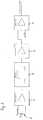
- Fig. 2 shows schematically a circuit diagram for a control device.
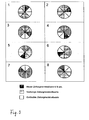
- Fig. 3 shows diagrammatically the formation of measured values for the flicker frequency of the flame radiation.
- a flame of an oil or gas burner burns optimally when a small stoichiometric excess air is present, ie the lambda value is slightly greater than one. If the lambda value continues to increase, the intensity of the flame radiation increases, which also happens when the lambda value drops below one. If the lambda value is greater than one, the optical frequencies of the air are shifted as the proportion of combustion air increases Flame radiation to larger values, with a lambda value smaller than one, the optical frequencies of the flame radiation shift to smaller values as the proportion of combustion air decreases. In the latter case, however, the development of soot also increases sharply (see diagram of Fig.
- the evaluation circuit can evaluate the signal of the photosensor with respect to Flackerfrequenz and / or amplitude of the detected flame radiation and upon detection of the emigration of flame radiation at a Flackerfrequenz below a predetermined value, a signal for increasing the combustion air content of the fuel-combustion air mixture and when the predetermined second Value generate a signal for lowering the combustion air content of the fuel-combustion air mixture.
- the diagram of FIG. 1 further includes a curve C which relates "zero crossings", here referred to as pulsation (Hz), of the signal of the flame radiation detecting photodetector 2 amplified by an amplifier 1 with respect to lambda.
- Hz pulsation
- These zero crossings per unit time essentially correspond Flicker frequency of flame radiation.
- These zero crossings are generated by the evaluation circuit by the DC component of the signal of the photo sensor is cut off and the zero line for the AC component is so placed that the noise component of the signal is suppressed, ie that the dominant amplitudes remain.
- the resulting AC signal is amplified, amplifier 3, such that substantially rectangular pulses with varying pulse widths result as a result of clipping the upper and lower sections.
- a comparator 4 either with downstream counter, a shift register and evaluation or a microprocessor 5 is expediently used, which performs the functions of these components and the generation of a shutdown signal in the event of missing flame.
- Low frequencies about ⁇ 30 Hz can be cut in advance by means of a high-pass filter 6 so that they do not enter into the evaluation.
- the limit for a shutdown is relatively small and periods may occur within the predetermined time in which no zero crossing is detected, it is appropriate to divide the predetermined time into a plurality, for example, six to ten sections, in which separately counted the zero crossings are then added after each expiration of a section for a predetermined time to corresponding values respectively after expiration of such a section for a predetermined time with the limit value to be able to compare.
- This is shown schematically in FIG.
- the required for gas and oil burners shutdown in a gas burner, for example, 1 sec, readily comply.
- the flame detector can be used in conjunction with any type of fuel-combustion air mixture control equipment.
- an optical filter in front of the photosensor which absorbs substantially in a wavelength range which corresponds to the radiation of glowing furnace walls (greater than approximately 900 nm), so that a flicker which can thereby be generated in the absence of a flame, that air is swirled by a fan in the oven, is not confused with the actual flickering of a flame.
Abstract
Description
Die Erfindung betrifft einen Flammenwächter für einen mit Öl oder Gas betriebenen Brenner nach dem Oberbegriff des Anspruchs 1. Ein solcher Flammenwächter ist aus Dokument
Aus
Aus
Aufgabe der Erfindung ist es, einen Flammenwächter nach dem Oberbegriff des Anspruchs 1 zu schaffen, die eine Erkennung, ob der Brenner brennt, d.h. eine Flamme vorhanden ist, in sehr einfacher Weise ermöglicht.The object of the invention is to provide a flame detector according to the preamble of
Diese Aufgabe wird entsprechend dem kennzeichnenden Teil des Anspruchs 1 gelöst.This object is achieved according to the characterizing part of
Weitere Ausgestaltungen der Erfindung sind der nachfolgenden Beschreibung und den Unteransprüchen zu entnehmen.Further embodiments of the invention are described in the following description and the dependent claims.
Die Erfindung wird nachstehend anhand von beigefügten Abbildungen näher erläutert.The invention is explained below with reference to accompanying drawings.
Fig. 1 zeigt ein Diagramm betreffend verschiedener Größen, aufgetragen gegenüber dem Lambda-Wert.Fig. 1 shows a diagram concerning various quantities plotted against the lambda value.
Fig. 2 zeigt schematisch ein Schaltkreisdiagramm für eine Regeleinrichtung.Fig. 2 shows schematically a circuit diagram for a control device.
Fig. 3 zeigt diagrammartig die Bildung von Meßwerten für die Flackerfrequenz der Flammenstrahlung.Fig. 3 shows diagrammatically the formation of measured values for the flicker frequency of the flame radiation.
Eine Flamme eines Öl- oder Gasbrenners brennt dann optimal, wenn ein geringer stöchiometrischer Luftüberschuß vorhanden, d.h. der Lambda-Wert geringfügig größer als eins ist. Steigt der Lambda-Wert weiter an, so nimmt die Intensität der Flammenstrahlung zu, was aber auch geschieht, wenn der Lambda-Wert unter eins abfällt. Bei einem Lambda-Wert größer eins verschieben sich bei Erhöhung des Verbrennungsluftanteils die optischen Frequenzen der Flammenstrahlung zu größeren Werten, bei einem Lambda-Wert kleiner eins verschieben sich bei Erniedrigung des Verbrennungsluftanteils die optischen Frequenzen der Flammenstrahlung zu kleineren Werten. In letzterem Fall steigt allerdings dann auch die Rußentwicklung stark an (vgl. Diagramm von Fig. 1, in dem Kurve A Meßwerte bezüglich der Rußentwicklung, in Bacharach angegeben, gegenüber dem Lambda-Wert aufgetragen zeigt), weshalb in diesem Fall dann, wenn über die Regelung die Rückführung des Brennstoff-Verbrennungsluftgemisches in den optimalen Bereich nicht in vorbestimmter Zeit erreicht wird, die Brennstoffzufuhr zweckmäßigerweise zu unterbrechen ist.A flame of an oil or gas burner burns optimally when a small stoichiometric excess air is present, ie the lambda value is slightly greater than one. If the lambda value continues to increase, the intensity of the flame radiation increases, which also happens when the lambda value drops below one. If the lambda value is greater than one, the optical frequencies of the air are shifted as the proportion of combustion air increases Flame radiation to larger values, with a lambda value smaller than one, the optical frequencies of the flame radiation shift to smaller values as the proportion of combustion air decreases. In the latter case, however, the development of soot also increases sharply (see diagram of Fig. 1, in which curve A shows measured values with respect to the development of soot, in Bacharach, plotted against the lambda value), which is why in this case, if the regulation the return of the fuel-combustion air mixture in the optimum range is not reached in a predetermined time, the fuel supply is expedient to interrupt.
Bei Verwendung eines die Flammenstrahlung erfassenden Fotosensors, der eine vom Ultraviolett zu Infrarot stark ansteigende Empfindlichkeit aufweist, und einer nachgeschalteten Auswerteschaltung, die ein Signal erzeugt, das dem über eine vorbestimmte Zeit integrierten Signal des Fotosensors bezüglich der Strahlung im Bereich größerer Wellenlängen, etwa >500 nm, entspricht, kann man das so erzeugte Signal gegenüber Lambda auftragen. Man erhält dann eine brennerspezifische Kurve B gemäß dem Diagramm von Fig. 1.When using a flame-detecting photosensor, which has a rising from ultraviolet to infrared sensitivity, and a downstream evaluation circuit that generates a signal that the over a predetermined time integrated signal of the photosensor with respect to the radiation in the range of larger wavelengths, about> 500 nm, it is possible to apply the signal thus generated to lambda. One then obtains a burner-specific curve B according to the diagram of FIG. 1.
Aus Kurve B ist ersichtlich, daß bei einem Lambda-Wert von etwa 1 ein Minimum liegt und die Kurve B von dort sowohl zu höheren wie zu niedrigeren Lambda-Werten hin ansteigt.From curve B it can be seen that at a lambda value of about 1 there is a minimum and curve B increases from there to both higher and lower lambda values.
Dementsprechend kann die Auswerteschaltung das Signal des Fotosensors bezüglich Flackerfrequenz und/oder Amplitude der erfaßten Flammenstrahlung auswerten und beim Feststellen des Auswanderns der Flammenstrahlung bei einer Flackerfrequenz unterhalb eines vorbestimmten Wertes ein Signal zum Erhöhen des Verbrennungsluftanteils des Brennstoff-Verbrennungsluft-Gemisches und beim Überschreiten des vorbestimmten zweiten Wertes ein Signal zum Erniedrigen des Verbrennungsluftanteils des Brennstoff-Verbrennungsluft-Gemisches erzeugen.Accordingly, the evaluation circuit can evaluate the signal of the photosensor with respect to Flackerfrequenz and / or amplitude of the detected flame radiation and upon detection of the emigration of flame radiation at a Flackerfrequenz below a predetermined value, a signal for increasing the combustion air content of the fuel-combustion air mixture and when the predetermined second Value generate a signal for lowering the combustion air content of the fuel-combustion air mixture.
Das Diagramm von Fig. 1 enthält ferner eine Kurve C, die "Nulldurchgänge", hier als Pulsation (Hz) bezeichnet, des von einem Verstärker 1 verstärkten Signals des die Flammenstrahlung erfassenden Fotodetektors 2 aufgetragen gegenüber Lambda betrifft. Diese Nulldurchgänge pro Zeiteinheit entsprechen im wesentlichen der Flackerfrequenz der Flammenstrahlung. Diese Nulldurchgänge werden von der Auswerteschaltung erzeugt, indem der Gleichstromanteil des Signals des Fotosensors abgeschnitten und die Nullinie für den Wechselstromanteil so gelegt wird, daß der Rauschanteil des Signals unterdrückt wird, d.h. daß die dominanten Amplituden übrig bleiben. Das sich ergebende Wechselspannungssignal wird derart verstärkt, Verstärker 3, daß sich infolge Abschneidens der oberen und unteren Abschnitte im wesentlichen Rechteckimpulse mit variierenden Pulsbreiten ergeben. Man zählt dann entsprechend auf- und/oder absteigende Flanken dieser Rechteckimpulse und damit Nulldurchgänge. Dies geschieht pro Zeiteinheit, beispielsweise pro Sekunde. Wenn die Zahl der Nulldurchgänge pro Zeiteinheit größer als ein vorbestimmter Grenzwert, beispielsweise 25, ist, geht man davon aus, daß eine Flamme vorhanden ist. Ist die Zahl der Nulldurchgänge gleich dem vorbestimmten Grenzwert oder darunter, geht man davon aus, daß keine Flamme vorhanden ist, und ein Signal zur Unterbrechung der Brennstoffzufuhr kann dementsprechend erzeugt. - Bei Auswertung der Nulldurchgänge läßt sich auf einen speziellen Fotodetektor und die zweikanalige Auswertung seines Signals nach
Zur Auswertung wird zweckmäßigerweise ein Komparator 4 entweder mit nachgeschaltetem Zähler, einem Schieberegister und Auswertung oder ein Mikroprozessor 5 verwendet, der die Funktionen dieser Komponenten und die Erzeugung eines Abschaltsignals für den Fall fehlender Flamme wahrnimmt. Niedrige Frequenzen etwa < 30 Hz können vorab mittels eines Hochpaßfilters 6 abgeschnitten werden, so daß sie nicht in die Auswertung eingehen.For evaluation, a
Da der Grenzwert für eine Abschaltung relativ klein ist und Perioden innerhalb der vorbestimmten Zeit auftreten können, in denen kein Nulldurchgang festgestellt wird, ist es zweckmäßig, die vorbestimmte Zeit in eine Vielzahl, beispielsweise sechs bis zehn Abschnitte zu unterteilen, in denen separat die Nulldurchgänge gezählt werden, die dann jeweils nach Ablauf eines Abschnittes für eine vorbestimmte Zeit addiert werden, um entsprechende Werte jeweils nach Ablauf eines derartiges Abschnitt für eine vorbestimmte Zeit mit dem Grenzwert vergleichen zu können. Dies ist in Fig. 3 schematisch dargestellt. Hierdurch lassen sich die bei Gas- und Ölbrennern geforderten Abschaltzeiten, bei einem Gasbrenner beispielsweise 1 sec, ohne weiteres einhalten. Bei der Erzeugung des jeweiligen Wertes für die Zahl der Nulldurchgänge fällt jeweils die Anzahl des zeitlich ersten Abschnittes weg und die Anzahl des zeitlich letzten Abschnittes kommt dazu, so daß der Wert nach jedem Abschnitt aktualisiert ist und mit dem Grenzwert verglichen werden kann. Hierzu benötigt man die oben erwähnte Schieberegisterfunktion.Since the limit for a shutdown is relatively small and periods may occur within the predetermined time in which no zero crossing is detected, it is appropriate to divide the predetermined time into a plurality, for example, six to ten sections, in which separately counted the zero crossings are then added after each expiration of a section for a predetermined time to corresponding values respectively after expiration of such a section for a predetermined time with the limit value to be able to compare. This is shown schematically in FIG. As a result, the required for gas and oil burners shutdown, in a gas burner, for example, 1 sec, readily comply. When the respective value for the number of zero crossings is generated, the number of the chronologically first segment disappears and the number of the chronologically last segment occurs, so that the value after each segment is updated and can be compared with the limit value. For this one needs the above-mentioned shift register function.
Bei dieser Art der Flammenüberwachung, die äußerst einfach ist, besteht auch keine Problem hinsichtlich Empfindlichkeitseinstellung, so daß er auch äußerst einfach handhabbar ist. Eine Übersteuerung spielt hierbei keine Rolle, da hierdurch die Rechteckimpulse nicht wesentlich beeinträchtigt werden. Der Flammenwächter läßt sich zusammen mit jeder Art von Regeleinrichtungen für das Brennstoff-Verbrennungsluft-Gemisch einsetzen.In this type of flame monitoring, which is extremely simple, there is also no problem with sensitivity adjustment, so that it is also extremely easy to handle. An override does not matter, as this does not significantly affect the rectangular pulses. The flame detector can be used in conjunction with any type of fuel-combustion air mixture control equipment.
Ferner ist es zweckmäßig, vor dem Fotosensor ein optisches Filter zu verwenden, das im wesentlichen in einem Wellenlängenbereich absorbierend wirkt, der der Strahlung von glühenden Ofenwänden entspricht (größer etwa 900 nm), damit ein Flackern, das bei fehlender Flamme dadurch erzeugt werden kann, daß durch einen Ventilator im Ofen Luft verwirbelt wird, nicht mit dem tatsächlichen Flackern einer Flamme verwechselt wird.Furthermore, it is expedient to use an optical filter in front of the photosensor which absorbs substantially in a wavelength range which corresponds to the radiation of glowing furnace walls (greater than approximately 900 nm), so that a flicker which can thereby be generated in the absence of a flame, that air is swirled by a fan in the oven, is not confused with the actual flickering of a flame.
Claims (6)
- Flame monitor for an oil- or gas-operated burner, having a photosensor which detects the optical flame radiation and the pulsation thereof, and having an evaluation circuit which is connected downstream of said photosensor and ascertains whether the radiation received by the photosensor corresponds to that of a burning flame and, in the event of a negative result, generates a switch-off signal for the fuel supply,
characterized in that the evaluation circuit determines the number of zero crossings of the processed signal of the photosensor within a predetermined unit of time and compares it with a predetermined limit value, a switch-off signal for the fuel supply being generated when said limit value is undershot, the signal of the photosensor, freed from the DC voltage component and noise, being processed by corresponding amplification to form square-wave pulses. - Flame monitor according to Claim 1, characterized in that the rising or falling edges of the signal can be counted by the evaluation circuit.
- Flame monitor according to Claim 2, characterized in that the evaluation circuit has a comparator with a counter connected downstream.
- Flame monitor according to one of Claims 1 to 3, characterized in that the predetermined unit of time is subdivided by the evaluation circuit into a multiplicity of segments, the number of zero crossings being determined at the end of each segment.
- Flame monitor according to Claim 4, characterized in that the segments form a fraction of the required burner switch-off time upon ascertaining the absence of a flame.
- Flame monitor according to one of Claims 1 to 5, characterized in that an optical filter is connected upstream of the photosensor and essentially absorbs radiation corresponding to that from incandescent furnace walls.
Applications Claiming Priority (2)
| Application Number | Priority Date | Filing Date | Title |
|---|---|---|---|
| DE10055831 | 2000-11-11 | ||
| DE10055831A DE10055831C2 (en) | 2000-11-11 | 2000-11-11 | Flame detector for an oil or gas burner |
Publications (3)
| Publication Number | Publication Date |
|---|---|
| EP1207346A2 EP1207346A2 (en) | 2002-05-22 |
| EP1207346A3 EP1207346A3 (en) | 2004-05-06 |
| EP1207346B1 true EP1207346B1 (en) | 2007-08-15 |
Family
ID=7662877
Family Applications (1)
| Application Number | Title | Priority Date | Filing Date |
|---|---|---|---|
| EP01126119A Expired - Lifetime EP1207346B1 (en) | 2000-11-11 | 2001-11-03 | Flame monitoring device for an oil or gas burner |
Country Status (4)
| Country | Link |
|---|---|
| US (1) | US6700495B2 (en) |
| EP (1) | EP1207346B1 (en) |
| AT (1) | ATE370372T1 (en) |
| DE (2) | DE10055831C2 (en) |
Cited By (1)
| Publication number | Priority date | Publication date | Assignee | Title |
|---|---|---|---|---|
| EP2105669A1 (en) | 2008-03-26 | 2009-09-30 | BFI Automation Dipl.-Ing. Kurt-Henry Mindermann GmbH | Flame monitoring and evaluation device |
Families Citing this family (14)
| Publication number | Priority date | Publication date | Assignee | Title |
|---|---|---|---|---|
| EP1665930A1 (en) | 2001-11-01 | 2006-06-07 | Integrated Biosystems Inc. | Systems and methods for freezing and storing biopharmaceutical material |
| DE102004051083B3 (en) * | 2004-10-19 | 2006-01-05 | Bfi Automation Dipl.-Ing. Kurt-Henry Mindermann Gmbh | Flame monitor for burner operated by fossil fuel self monitoring unit with modulatable light source by which flame monitoring unit signals flame out state if it establishes modulated light longer than threshold value |
| ES2381512B1 (en) * | 2009-06-04 | 2013-05-07 | Coprecitec, S.L | DOMESTIC GAS DEVICE WITH FLAME CONTROL |
| US9388984B2 (en) | 2010-04-09 | 2016-07-12 | Honeywell International Inc. | Flame detection in a fuel fired appliance |
| US8523560B2 (en) | 2010-04-09 | 2013-09-03 | Honeywell International Inc. | Spark detection in a fuel fired appliance |
| US8177544B2 (en) | 2010-04-09 | 2012-05-15 | Honeywell International Inc. | Selective lockout in a fuel-fired appliance |
| ES2446317T3 (en) * | 2010-10-08 | 2014-03-07 | Bfi Automation Dipl.-Ing. Kurt-Henry Mindermann Gmbh | Device to detect the presence of a flame |
| US9863813B2 (en) | 2012-04-13 | 2018-01-09 | General Electric Company | Flame sensor |
| US9494320B2 (en) | 2013-01-11 | 2016-11-15 | Honeywell International Inc. | Method and system for starting an intermittent flame-powered pilot combustion system |
| US10208954B2 (en) | 2013-01-11 | 2019-02-19 | Ademco Inc. | Method and system for controlling an ignition sequence for an intermittent flame-powered pilot combustion system |
| US11619384B2 (en) * | 2017-04-24 | 2023-04-04 | General Electric Technology Gmbh | System and method for operating a combustion chamber |
| US11236930B2 (en) | 2018-05-01 | 2022-02-01 | Ademco Inc. | Method and system for controlling an intermittent pilot water heater system |
| US11739982B2 (en) | 2019-08-14 | 2023-08-29 | Ademco Inc. | Control system for an intermittent pilot water heater |
| US11656000B2 (en) | 2019-08-14 | 2023-05-23 | Ademco Inc. | Burner control system |
Family Cites Families (9)
| Publication number | Priority date | Publication date | Assignee | Title |
|---|---|---|---|---|
| DE2823410A1 (en) * | 1978-04-25 | 1979-11-08 | Cerberus Ag | FLAME DETECTOR |
| US4280184A (en) * | 1979-06-26 | 1981-07-21 | Electronic Corporation Of America | Burner flame detection |
| DD261199A1 (en) * | 1985-12-23 | 1988-10-19 | Geraete & Regler Werke Veb | ALTERNATING RADIATION FLAME WEAPON WITH NOISE SIGNAL SUPPRESSION |
| US5126721A (en) * | 1990-10-23 | 1992-06-30 | The United States Of America As Represented By The United States Department Of Energy | Flame quality monitor system for fixed firing rate oil burners |
| US5424554A (en) * | 1994-03-22 | 1995-06-13 | Energy Kenitics, Inc. | Oil-burner, flame-intensity, monitoring system and method of operation with an out of range signal discriminator |
| DE19650972C2 (en) * | 1996-12-09 | 2001-02-01 | Elbau Elektronik Bauelemente G | Method and arrangement for monitoring and regulating combustion processes |
| DE19746786C2 (en) * | 1997-10-23 | 2000-10-26 | Giersch Gmbh Oel Und Gasbrenne | Optical flame detector |
| DE19809653C1 (en) | 1998-03-06 | 1999-09-16 | Giersch Gmbh | Flame monitor for blue flame for e.g. safe operation of burner |
| US6261086B1 (en) * | 2000-05-05 | 2001-07-17 | Forney Corporation | Flame detector based on real-time high-order statistics |
-
2000
- 2000-11-11 DE DE10055831A patent/DE10055831C2/en not_active Expired - Lifetime
-
2001
- 2001-11-03 DE DE50112856T patent/DE50112856D1/en not_active Expired - Lifetime
- 2001-11-03 AT AT01126119T patent/ATE370372T1/en not_active IP Right Cessation
- 2001-11-03 EP EP01126119A patent/EP1207346B1/en not_active Expired - Lifetime
- 2001-11-09 US US10/005,488 patent/US6700495B2/en not_active Expired - Lifetime
Non-Patent Citations (1)
| Title |
|---|
| None * |
Cited By (1)
| Publication number | Priority date | Publication date | Assignee | Title |
|---|---|---|---|---|
| EP2105669A1 (en) | 2008-03-26 | 2009-09-30 | BFI Automation Dipl.-Ing. Kurt-Henry Mindermann GmbH | Flame monitoring and evaluation device |
Also Published As
| Publication number | Publication date |
|---|---|
| EP1207346A2 (en) | 2002-05-22 |
| DE10055831C2 (en) | 2002-11-21 |
| ATE370372T1 (en) | 2007-09-15 |
| US20020081545A1 (en) | 2002-06-27 |
| US6700495B2 (en) | 2004-03-02 |
| DE50112856D1 (en) | 2007-09-27 |
| DE10055831A1 (en) | 2002-05-29 |
| EP1207346A3 (en) | 2004-05-06 |
Similar Documents
| Publication | Publication Date | Title |
|---|---|---|
| EP1207346B1 (en) | Flame monitoring device for an oil or gas burner | |
| EP0953805B1 (en) | Flame monitor | |
| EP0806610B1 (en) | Method for operating a gas burner | |
| DE19502901C1 (en) | Regulating device for gas burner | |
| DE19841475C1 (en) | Flame monitoring system for gas-, oil- or coal-fired burner | |
| DE19539568C1 (en) | Gas burner regulation system | |
| DE3728308C2 (en) | ||
| EP0770824A2 (en) | Method and circuit for controlling a gas burner | |
| DE2436695A1 (en) | METHOD AND DEVICE FOR FLAME DETECTION | |
| DE10023273A1 (en) | Measuring device for a flame | |
| DE4433425A1 (en) | Control appts. for adjusting gas to air mixture in gas burner esp. gas torch burner | |
| DE102005015754A1 (en) | Ventilation unit | |
| DE2611763C2 (en) | Flame supervision circuit | |
| EP0718814B1 (en) | Method and device for flame detection | |
| EP1002997B1 (en) | Method for controlling a fuel/air ratio of full premix gas burner | |
| DE19650972C2 (en) | Method and arrangement for monitoring and regulating combustion processes | |
| EP1207345B1 (en) | Device for controlling the air-fuel ratio for an oil or gas burner | |
| DE2413482A1 (en) | DEVICE FOR MONITORING THE FLAMES FROM BURNERS | |
| DE19746786C2 (en) | Optical flame detector | |
| DE19632983C2 (en) | Control device for a gas burner | |
| CH694379A5 (en) | Flame detector. | |
| DE60014980T2 (en) | Flame monitoring in a burner | |
| EP2154430B1 (en) | Control device for a gas burner, and use of the control device | |
| DE19631821A1 (en) | Gas burner operating method for gas heater | |
| DE2326067A1 (en) | METHOD AND DEVICE FOR FLAME MONITORING |
Legal Events
| Date | Code | Title | Description |
|---|---|---|---|
| PUAI | Public reference made under article 153(3) epc to a published international application that has entered the european phase |
Free format text: ORIGINAL CODE: 0009012 |
|
| AX | Request for extension of the european patent |
Free format text: AL;LT;LV;MK;RO;SI |
|
| PUAL | Search report despatched |
Free format text: ORIGINAL CODE: 0009013 |
|
| AK | Designated contracting states |
Kind code of ref document: A3 Designated state(s): AT BE CH CY DE DK ES FI FR GB GR IE IT LI LU MC NL PT SE TR |
|
| AX | Request for extension of the european patent |
Extension state: AL LT LV MK RO SI |
|
| 17P | Request for examination filed |
Effective date: 20040909 |
|
| AKX | Designation fees paid |
Designated state(s): AT BE CH CY DE DK ES FI FR GB GR IE IT LI LU MC NL PT SE TR |
|
| GRAP | Despatch of communication of intention to grant a patent |
Free format text: ORIGINAL CODE: EPIDOSNIGR1 |
|
| GRAS | Grant fee paid |
Free format text: ORIGINAL CODE: EPIDOSNIGR3 |
|
| GRAA | (expected) grant |
Free format text: ORIGINAL CODE: 0009210 |
|
| AK | Designated contracting states |
Kind code of ref document: B1 Designated state(s): AT BE CH CY DE DK ES FI FR GB GR IE IT LI LU MC NL PT SE TR |
|
| REG | Reference to a national code |
Ref country code: GB Ref legal event code: FG4D Free format text: NOT ENGLISH |
|
| REG | Reference to a national code |
Ref country code: CH Ref legal event code: EP |
|
| REG | Reference to a national code |
Ref country code: IE Ref legal event code: FG4D Free format text: LANGUAGE OF EP DOCUMENT: GERMAN |
|
| REF | Corresponds to: |
Ref document number: 50112856 Country of ref document: DE Date of ref document: 20070927 Kind code of ref document: P |
|
| PG25 | Lapsed in a contracting state [announced via postgrant information from national office to epo] |
Ref country code: NL Free format text: LAPSE BECAUSE OF FAILURE TO SUBMIT A TRANSLATION OF THE DESCRIPTION OR TO PAY THE FEE WITHIN THE PRESCRIBED TIME-LIMIT Effective date: 20070815 Ref country code: FI Free format text: LAPSE BECAUSE OF FAILURE TO SUBMIT A TRANSLATION OF THE DESCRIPTION OR TO PAY THE FEE WITHIN THE PRESCRIBED TIME-LIMIT Effective date: 20070815 Ref country code: ES Free format text: LAPSE BECAUSE OF FAILURE TO SUBMIT A TRANSLATION OF THE DESCRIPTION OR TO PAY THE FEE WITHIN THE PRESCRIBED TIME-LIMIT Effective date: 20071126 |
|
| NLV1 | Nl: lapsed or annulled due to failure to fulfill the requirements of art. 29p and 29m of the patents act | ||
| GBV | Gb: ep patent (uk) treated as always having been void in accordance with gb section 77(7)/1977 [no translation filed] |
Effective date: 20070815 |
|
| ET | Fr: translation filed | ||
| REG | Reference to a national code |
Ref country code: IE Ref legal event code: FD4D |
|
| PG25 | Lapsed in a contracting state [announced via postgrant information from national office to epo] |
Ref country code: DK Free format text: LAPSE BECAUSE OF FAILURE TO SUBMIT A TRANSLATION OF THE DESCRIPTION OR TO PAY THE FEE WITHIN THE PRESCRIBED TIME-LIMIT Effective date: 20070815 Ref country code: GR Free format text: LAPSE BECAUSE OF FAILURE TO SUBMIT A TRANSLATION OF THE DESCRIPTION OR TO PAY THE FEE WITHIN THE PRESCRIBED TIME-LIMIT Effective date: 20071116 |
|
| PG25 | Lapsed in a contracting state [announced via postgrant information from national office to epo] |
Ref country code: GB Free format text: LAPSE BECAUSE OF FAILURE TO SUBMIT A TRANSLATION OF THE DESCRIPTION OR TO PAY THE FEE WITHIN THE PRESCRIBED TIME-LIMIT Effective date: 20070815 Ref country code: PT Free format text: LAPSE BECAUSE OF FAILURE TO SUBMIT A TRANSLATION OF THE DESCRIPTION OR TO PAY THE FEE WITHIN THE PRESCRIBED TIME-LIMIT Effective date: 20080115 Ref country code: IE Free format text: LAPSE BECAUSE OF FAILURE TO SUBMIT A TRANSLATION OF THE DESCRIPTION OR TO PAY THE FEE WITHIN THE PRESCRIBED TIME-LIMIT Effective date: 20070815 |
|
| BERE | Be: lapsed |
Owner name: BFI AUTOMATION DIPL.-ING. KURT-HENRY MINDERMANN G Effective date: 20071130 |
|
| PLBE | No opposition filed within time limit |
Free format text: ORIGINAL CODE: 0009261 |
|
| STAA | Information on the status of an ep patent application or granted ep patent |
Free format text: STATUS: NO OPPOSITION FILED WITHIN TIME LIMIT |
|
| PG25 | Lapsed in a contracting state [announced via postgrant information from national office to epo] |
Ref country code: SE Free format text: LAPSE BECAUSE OF FAILURE TO SUBMIT A TRANSLATION OF THE DESCRIPTION OR TO PAY THE FEE WITHIN THE PRESCRIBED TIME-LIMIT Effective date: 20071115 Ref country code: MC Free format text: LAPSE BECAUSE OF NON-PAYMENT OF DUE FEES Effective date: 20071130 |
|
| 26N | No opposition filed |
Effective date: 20080516 |
|
| PG25 | Lapsed in a contracting state [announced via postgrant information from national office to epo] |
Ref country code: LI Free format text: LAPSE BECAUSE OF NON-PAYMENT OF DUE FEES Effective date: 20071130 Ref country code: CH Free format text: LAPSE BECAUSE OF NON-PAYMENT OF DUE FEES Effective date: 20071130 |
|
| REG | Reference to a national code |
Ref country code: CH Ref legal event code: PL |
|
| PG25 | Lapsed in a contracting state [announced via postgrant information from national office to epo] |
Ref country code: BE Free format text: LAPSE BECAUSE OF NON-PAYMENT OF DUE FEES Effective date: 20071130 |
|
| PG25 | Lapsed in a contracting state [announced via postgrant information from national office to epo] |
Ref country code: AT Free format text: LAPSE BECAUSE OF NON-PAYMENT OF DUE FEES Effective date: 20071103 |
|
| PG25 | Lapsed in a contracting state [announced via postgrant information from national office to epo] |
Ref country code: CY Free format text: LAPSE BECAUSE OF FAILURE TO SUBMIT A TRANSLATION OF THE DESCRIPTION OR TO PAY THE FEE WITHIN THE PRESCRIBED TIME-LIMIT Effective date: 20070815 |
|
| PG25 | Lapsed in a contracting state [announced via postgrant information from national office to epo] |
Ref country code: LU Free format text: LAPSE BECAUSE OF NON-PAYMENT OF DUE FEES Effective date: 20071103 |
|
| PG25 | Lapsed in a contracting state [announced via postgrant information from national office to epo] |
Ref country code: TR Free format text: LAPSE BECAUSE OF FAILURE TO SUBMIT A TRANSLATION OF THE DESCRIPTION OR TO PAY THE FEE WITHIN THE PRESCRIBED TIME-LIMIT Effective date: 20070815 |
|
| REG | Reference to a national code |
Ref country code: DE Ref legal event code: R082 Ref document number: 50112856 Country of ref document: DE Representative=s name: SPARING - ROEHL - HENSELER, DE Ref country code: DE Ref legal event code: R081 Ref document number: 50112856 Country of ref document: DE Owner name: BFI AUTOMATION MINDERMANN GMBH, DE Free format text: FORMER OWNER: BFI AUTOMATION DIPL.-ING. KURT-HENRY MINDERMANN GMBH, 40883 RATINGEN, DE |
|
| REG | Reference to a national code |
Ref country code: DE Ref legal event code: R082 Ref document number: 50112856 Country of ref document: DE Representative=s name: SPARING - ROEHL - HENSELER, DE Ref country code: DE Ref legal event code: R081 Ref document number: 50112856 Country of ref document: DE Owner name: BFI AUTOMATION MINDERMANN GMBH, DE Free format text: FORMER OWNER: BFI AUTOMATION MINDERMANN GMBH, 40883 RATINGEN, DE |
|
| REG | Reference to a national code |
Ref country code: FR Ref legal event code: PLFP Year of fee payment: 15 |
|
| REG | Reference to a national code |
Ref country code: FR Ref legal event code: CD Owner name: BFI AUTOMATION MINDERMANN GMBH Effective date: 20151130 |
|
| REG | Reference to a national code |
Ref country code: FR Ref legal event code: RM Effective date: 20160527 |
|
| REG | Reference to a national code |
Ref country code: FR Ref legal event code: PLFP Year of fee payment: 16 |
|
| REG | Reference to a national code |
Ref country code: FR Ref legal event code: PLFP Year of fee payment: 17 |
|
| PGFP | Annual fee paid to national office [announced via postgrant information from national office to epo] |
Ref country code: FR Payment date: 20201120 Year of fee payment: 20 Ref country code: IT Payment date: 20201124 Year of fee payment: 20 |
|
| PGFP | Annual fee paid to national office [announced via postgrant information from national office to epo] |
Ref country code: DE Payment date: 20210128 Year of fee payment: 20 |
|
| REG | Reference to a national code |
Ref country code: DE Ref legal event code: R071 Ref document number: 50112856 Country of ref document: DE |