EP1207277A1 - Oil pump mounting structure for engine - Google Patents
Oil pump mounting structure for engine Download PDFInfo
- Publication number
- EP1207277A1 EP1207277A1 EP01121945A EP01121945A EP1207277A1 EP 1207277 A1 EP1207277 A1 EP 1207277A1 EP 01121945 A EP01121945 A EP 01121945A EP 01121945 A EP01121945 A EP 01121945A EP 1207277 A1 EP1207277 A1 EP 1207277A1
- Authority
- EP
- European Patent Office
- Prior art keywords
- oil
- pump
- crank
- shaft
- valve
- Prior art date
- Legal status (The legal status is an assumption and is not a legal conclusion. Google has not performed a legal analysis and makes no representation as to the accuracy of the status listed.)
- Granted
Links
Images


Classifications
-
- F—MECHANICAL ENGINEERING; LIGHTING; HEATING; WEAPONS; BLASTING
- F02—COMBUSTION ENGINES; HOT-GAS OR COMBUSTION-PRODUCT ENGINE PLANTS
- F02F—CYLINDERS, PISTONS OR CASINGS, FOR COMBUSTION ENGINES; ARRANGEMENTS OF SEALINGS IN COMBUSTION ENGINES
- F02F1/00—Cylinders; Cylinder heads
- F02F1/24—Cylinder heads
- F02F1/42—Shape or arrangement of intake or exhaust channels in cylinder heads
- F02F1/4214—Shape or arrangement of intake or exhaust channels in cylinder heads specially adapted for four or more valves per cylinder
-
- F—MECHANICAL ENGINEERING; LIGHTING; HEATING; WEAPONS; BLASTING
- F01—MACHINES OR ENGINES IN GENERAL; ENGINE PLANTS IN GENERAL; STEAM ENGINES
- F01M—LUBRICATING OF MACHINES OR ENGINES IN GENERAL; LUBRICATING INTERNAL COMBUSTION ENGINES; CRANKCASE VENTILATING
- F01M1/00—Pressure lubrication
- F01M1/02—Pressure lubrication using lubricating pumps
-
- F—MECHANICAL ENGINEERING; LIGHTING; HEATING; WEAPONS; BLASTING
- F01—MACHINES OR ENGINES IN GENERAL; ENGINE PLANTS IN GENERAL; STEAM ENGINES
- F01M—LUBRICATING OF MACHINES OR ENGINES IN GENERAL; LUBRICATING INTERNAL COMBUSTION ENGINES; CRANKCASE VENTILATING
- F01M11/00—Component parts, details or accessories, not provided for in, or of interest apart from, groups F01M1/00 - F01M9/00
- F01M11/0004—Oilsumps
-
- F—MECHANICAL ENGINEERING; LIGHTING; HEATING; WEAPONS; BLASTING
- F02—COMBUSTION ENGINES; HOT-GAS OR COMBUSTION-PRODUCT ENGINE PLANTS
- F02B—INTERNAL-COMBUSTION PISTON ENGINES; COMBUSTION ENGINES IN GENERAL
- F02B75/00—Other engines
- F02B75/16—Engines characterised by number of cylinders, e.g. single-cylinder engines
- F02B75/18—Multi-cylinder engines
- F02B75/24—Multi-cylinder engines with cylinders arranged oppositely relative to main shaft and of "flat" type
- F02B75/243—Multi-cylinder engines with cylinders arranged oppositely relative to main shaft and of "flat" type with only one crankshaft of the "boxer" type, e.g. all connecting rods attached to separate crankshaft bearings
-
- F—MECHANICAL ENGINEERING; LIGHTING; HEATING; WEAPONS; BLASTING
- F01—MACHINES OR ENGINES IN GENERAL; ENGINE PLANTS IN GENERAL; STEAM ENGINES
- F01M—LUBRICATING OF MACHINES OR ENGINES IN GENERAL; LUBRICATING INTERNAL COMBUSTION ENGINES; CRANKCASE VENTILATING
- F01M11/00—Component parts, details or accessories, not provided for in, or of interest apart from, groups F01M1/00 - F01M9/00
- F01M11/0004—Oilsumps
- F01M2011/005—Oilsumps with special anti-turbulence means, e.g. anti-foaming means or intermediate plates
-
- F—MECHANICAL ENGINEERING; LIGHTING; HEATING; WEAPONS; BLASTING
- F01—MACHINES OR ENGINES IN GENERAL; ENGINE PLANTS IN GENERAL; STEAM ENGINES
- F01M—LUBRICATING OF MACHINES OR ENGINES IN GENERAL; LUBRICATING INTERNAL COMBUSTION ENGINES; CRANKCASE VENTILATING
- F01M11/00—Component parts, details or accessories, not provided for in, or of interest apart from, groups F01M1/00 - F01M9/00
- F01M11/0004—Oilsumps
- F01M2011/0066—Oilsumps with passages in the wall, e.g. for axles or fluid passages
-
- F—MECHANICAL ENGINEERING; LIGHTING; HEATING; WEAPONS; BLASTING
- F01—MACHINES OR ENGINES IN GENERAL; ENGINE PLANTS IN GENERAL; STEAM ENGINES
- F01M—LUBRICATING OF MACHINES OR ENGINES IN GENERAL; LUBRICATING INTERNAL COMBUSTION ENGINES; CRANKCASE VENTILATING
- F01M11/00—Component parts, details or accessories, not provided for in, or of interest apart from, groups F01M1/00 - F01M9/00
- F01M11/0004—Oilsumps
- F01M2011/0079—Oilsumps with the oil pump integrated or fixed to sump
-
- F—MECHANICAL ENGINEERING; LIGHTING; HEATING; WEAPONS; BLASTING
- F02—COMBUSTION ENGINES; HOT-GAS OR COMBUSTION-PRODUCT ENGINE PLANTS
- F02B—INTERNAL-COMBUSTION PISTON ENGINES; COMBUSTION ENGINES IN GENERAL
- F02B2275/00—Other engines, components or details, not provided for in other groups of this subclass
- F02B2275/10—Diamond configuration of valves in cylinder heads
-
- F—MECHANICAL ENGINEERING; LIGHTING; HEATING; WEAPONS; BLASTING
- F02—COMBUSTION ENGINES; HOT-GAS OR COMBUSTION-PRODUCT ENGINE PLANTS
- F02B—INTERNAL-COMBUSTION PISTON ENGINES; COMBUSTION ENGINES IN GENERAL
- F02B2275/00—Other engines, components or details, not provided for in other groups of this subclass
- F02B2275/34—Lateral camshaft position
-
- F—MECHANICAL ENGINEERING; LIGHTING; HEATING; WEAPONS; BLASTING
- F02—COMBUSTION ENGINES; HOT-GAS OR COMBUSTION-PRODUCT ENGINE PLANTS
- F02F—CYLINDERS, PISTONS OR CASINGS, FOR COMBUSTION ENGINES; ARRANGEMENTS OF SEALINGS IN COMBUSTION ENGINES
- F02F1/00—Cylinders; Cylinder heads
- F02F1/24—Cylinder heads
- F02F2001/244—Arrangement of valve stems in cylinder heads
- F02F2001/245—Arrangement of valve stems in cylinder heads the valve stems being orientated at an angle with the cylinder axis
Definitions
- the present invention relates to an engine including a crank case rotatably supported by a crank case, an oil pan connected to a lower portion of the crank case, and an oil pump rotatable in interlocking with the crank shaft, and particularly to an improved oil pump mounting structure for the engine.
- a pump housing of an oil pump has been often removably mounted on a lower portion of a crank case, as disclosed, for example, in Japanese Patent Publication No. Sho 62-34950.
- an object of the present invention is to provide an oil pump mounting structure for an engine, which is capable of making the center of gravity of the engine relatively low, and improving both the suction efficiency and maintenance characteristic of the oil pump.
- an oil pump mounting structure for an engine including a crank case rotatably supporting a crank shaft, an oil pan connected to a lower portion of the crank case, and an oil pump rotatable in interlocking with the crank shaft, characterized in that a pump housing of the oil pump is removably mounted on a mounting portion provided on the bottom of the oil pan.
- an oil strainer connected to an inlet of the oil pump is fixedly held between the oil pan and the pump housing.
- a relief valve connected to an outlet of the oil pump is fixedly connected between the oil pan and the pump housing in the direction parallel to the direction where the oil strainer is held, and an oil filter connected to the outlet is mounted to an outer surface of a side wall of the oil pan.
- a partition wall is provided in the pump housing so that a power transmission chamber partitioned from an oil reservoir chamber formed in the oil pan is formed between the partition wall and a side wall of the oil pan; and a rotating member rotatable by power transmission from the crank shaft is fixed to an end portion, on the power transmission chamber side, of a drive shaft rotatably supported by the pump housing.
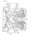
- FIGS 1 to 10 show one embodiment in which the present invention is applied to a four-cycle horizontal opposed type two-cylinder engine, wherein FIG. 1 is a vertical sectional rear view of the engine; FIG. 2 is an enlarged sectional view taken on line 2-2 of FIG. 1; FIG. 3 is an enlarged sectional view taken on line 3-3 of FIG. 2; FIG. 4 is an enlarged sectional view taken on line 4-4 of FIG. 2; FIG. 5 is a sectional view taken on line 5-5 of FIG. 1 showing a cylinder head; FIG. 6 is a sectional view taken on line 6-6 of FIG. 5 showing the cylinder head in a state in which a head cover is removed; FIG. 7 is a view seen along an arrow 7 of FIG. 6; FIG. 8 is a sectional view taken on line 8-8 of FIG. 7; FIG. 9 is a sectional view taken on line 9-9 of FIG. 1; and FIG. 10 is an exploded perspective view of a structure for connecting a pull rod to a cam follower.
- a main body 11 of the engine E includes a left engine block 12L disposed on the left side as seen from the rear side of the engine E and a right engine block 12R disposed on the right side as seen from the rear side of the engine E.
- the left engine block 12L includes a left cylinder block 13L, a left crank case 14L formed integrally with the left cylinder block 13L, and a left cylinder head 15L connected to the side, opposite to the left crank case 14L, of the left cylinder block 13L.
- the right engine block 12R includes a right cylinder block 13R, a right crank case 14R formed integrally with the right cylinder block 13R, and a right cylinder head 15R connected to the side, opposite to the right crank case 14R, of the right cylinder block 13R.
- the cylinder block 13L (or 13R) has a cylinder bore 16L (or 16R).
- a piston 18L (or 18R) is slidably fitted in the cylinder bore 16L (or 16R) in such a manner as to form a combustion chamber 17L (or 17R) between the cylinder bore 16L (or 16R) and the cylinder head 15L (or 15R).
- Both the engine blocks 12L and 12R are oppositely disposed with axial lines of the cylinder bores 16L and 16R kept substantially in the horizontal direction.
- the left and right crank cases 14L and 14R are fastened to each other to form a crank case 19 in cooperation with each other.
- a crank shaft 21 connected to the pistons 18L and 18R via connecting rods 20L and 20R is rotatably supported between the left and right crank cases 14L and 14R.
- the crank case 19 is provided with a front journal wall 22F, an intermediate journal wall 22M, and a rear journal wall 22R, which are spaced from each other in the longitudinal direction. Three portions, spaced from each other in the axial direction, of the crank shaft 21 are rotatably supported by these journal walls 22F, 22M and 22R.
- the crank shaft 21 is housed in a crank chamber 24 formed in the crank case 19, and a partition wall 25 defining the bottom of the crank chamber 24 is provided on the inner wall of the crank case 19.
- a rear end portion (left end portion in FIG. 2) of the crank shaft 21 projects rearwardly from the rear journal wall 22R.
- a rotor 27 of a generator 26 is coaxially connected to the rear end portion of the crank shaft 21, and a stator 28 of the generator 26 is disposed behind the rear journal wall 22R and is fixedly supported by a supporting plate 29 fixed to the crank case 19.
- a cover 30 for covering the generator 26 is fastened to a rear portion of the crank case 19.
- a drive gear 31 is fixed to the crank shaft 21 at a position between the rear journal wall 22R and the supporting plate 29.
- a rotating shaft 33 to which a first intermediate gear 32 meshing with the drive gear 31, is rotatably supported by the rear journal wall 22R and the supporting plate 29.
- a second intermediate gear 34 which is integrally provided on the rotating shaft 33, meshes with a gear 35 provided on a cam shaft 36.
- the cam shaft 36 having an axial line parallel to the crank shaft 21 is rotatably supported by the crank case 19 at a position under the partition wall 25.
- a water pump 37 is mounted to the cover 30.
- a pump shaft 38 of the water pump 37 is coaxially connected to the rotating shaft 33 in such a manner as not to be rotated relative to the rotating shaft 33, whereby a rotational power is transmitted from the crank shaft 21 to the water pump 37.
- an oil pan 42 is connected to a lower portion of the crank case 19 in such a manner as to form an oil reservoir chamber 43 under the cam shaft 36.
- An oil pump 44 configured as a trochoide pump is housed in the oil pan 42.
- a pump housing 45 of the oil pump 44 is formed by connecting a pair of housing halves 46 and 47 to each other.
- a drive shaft 48 having an axial line parallel to the crank shaft 21 and the cam shaft 36 is rotatably supported by the housing half 46.
- the drive shaft 48 is connected to a rotor 49 disposed between both the housing halves 46 and 47.
- a partition wall 46a is integrally provided on the housing half 46, whereby a power transmission chamber 50 partitioned from the oil reservoir chamber 43 formed in the oil pan 42 is formed between the partition wall 46a and a side wall of the oil pan 42.
- a gear 51 meshing with the gear 35 of the cam shaft 36 rotated by a power transmitted from the crank shaft 21 is fixed to an end portion, on the power transmission chamber 50 side, of the drive shaft 48. In this way, a rotational power is transmitted from the crank shaft 21 to the oil pump 44.
- the partition wall 46a has an approximately U-shaped transverse cross-section opened upwardly.
- the upper end of the partition wall 46a is located at a position higher than an oil level L of oil reserved in the oil reservoir chamber 43, so that oil does not flow from the oil reservoir chamber 43 side to the power transmission chamber 50 side.
- oil flows from the crank chamber 24 side into the power transmission chamber 50 via a gear train disposed in the power transmission route from the crank shaft 21 to the gear 51, the oil in the power transmission chamber 50 is splashed to the oil reservoir chamber 43 side across the upper end of the partition wall 46a by rotation of the gear 51.
- a pair of boss-like mounting portions 52 are integrally provided on a portion, corresponding to the housing half 46, of the bottom of the oil pan 42 in such a manner as to project therefrom.
- the housing half 46 is removably mounted on the mounting portions 52 with bolts 53.
- a pair of boss-like mounting portions 52 are integrally provided on a portion, corresponding to the housing half 47, of the bottom of the oil pan 42 in such a manner as to project therefrom.
- the housing half 47 is removably mounted on the mounting portions 52 with bolts 53. That is to say, the pump housing 45 is removably mounted on the mounting portions 52 provided on the bottom of the oil pan 42.
- An inlet 54 is provided in the housing half 46 of the pump housing 45, and an oil strainer 55 connected to the inlet 54 is fixedly held between the housing half 46 and the oil pan 42.
- an upper portion of the oil strainer 55 is inserted from below in a lower portion of the housing half 46 in such a manner as to be continuous to the inlet 54, and a lower peripheral edge of the oil strainer 55 is received on a receiving portion 56 provided on the bottom of the oil pan 42.
- An outlet 57 is provided in the housing half 47 of the pump housing 45, and a relief valve 58 connected to the outlet 57 is fixedly held between the housing half 47 and the oil pan 42 while being kept in a posture parallel to that of the oil strainer 55.
- an upper portion of the relief valve 58 is inserted from below in a lower portion of the housing half 47 in such a manner as to be continuous to the outlet 57, and a lower end of the relief valve 58 is received by a raised portion 59 provided on the bottom of the oil pan 42.
- An oil passage 61 communicated to the outlet 57 is provided in the housing half 47.
- An oil passage 62 communicated to the oil passage 61 is provided in the lower portion of the oil pan 42 when the pump housing 45 is mounted to the oil pan 42.
- An oil filter 63 connected to the oil passage 62 is removably mounted to an outer surface of a side wall of the oil pan 42.
- An oil passage 64 for leading oil cleaned through the oil filter 63 is provided in both the oil pan 42 and the crank case 19, which passage is communicated to a main gallery 65 provided in the crank case 19.
- a front portion of the crank shaft 21 is formed into a cylindrical hollow shape for reducing the weight of the crank shaft 21.
- a cylindrical spacer 66 having an annular chamber 67 formed between the inner surface of the crank shaft 21 and the outer surface of the spacer 66, is fitted in the cylindrical hollow portion of the crank shaft 21.
- the annular chamber 67 extends at least between portions corresponding to the front and intermediate journal walls 22F and 22M of the crank case 19. Both axial ends of the annular chamber 67 are fluid-tightly sealed by mounting seal members to both ends of the spacer 66 or press-fitting both the ends of the spacer 66 in the crank shaft 21.
- An oil passage 68 for supplying oil to a portion to be lubricated between the intermediate journal wall 22M and the crank shaft 21 is provided in the crank case 19 in such a manner as to be communicated to the main gallery 65.
- the crank shaft 21 has a passage hole 69 for leading the oil from the portion to be lubricated between the intermediate journal wall 22M and the crank shaft 21 to the annular chamber 67, and a passage hole 70 for leading oil from the annular chamber 67 to a portion to be lubricated between the front journal wall 22F and the crank shaft 21.
- the crank shaft 21 integrally includes a crank pin 21L connected to the connecting rod 20L on the left engine block 12L side and a crank pin 21R connected to the connecting rod 20R on the right engine block 12R side.
- An oil passage 71 for leading the oil from the annular chamber 67 to a portion to be lubricated between the connecting rod 20L and the crank pin 21L is provided in the crank shaft 21.
- Oil is supplied from the main gallery 65 to a portion to be lubricated between the rear journal wall 22R and the crank shaft 21.
- An oil passage 72 for leading the oil from the portion to be lubricated between the rear journal wall 22R and the crank shaft 21 to a portion to be lubricated between the connecting rod 20R and the crank pin 21R is provided in the crank shaft 21.
- the entire cylindrical hollow portion of the crank shaft 21 can be used as an oil passage; however, in this case, since the volume of the oil passage becomes excessively large, there may occur inconveniences that a hydraulic pressure rising time upon start-up of the engine E be retarded and a residual amount of oil upon oil exchange be increased.
- the annular chamber 67 formed between the cylindrical hollow portion of the crank shaft 21 and the spacer 66 is, as described above, used as the oil passage, the passage volume can be set to a suitable value, to prevent the retardation of the hydraulic pressure rising time and to prevent the increase in residual amount of oil upon oil exchange.
- crank shaft 21 since the inside diameter of the cylindrical hollow portion of the crank shaft 21 can be set to a relatively large value without increasing the passage volume, it is not required to increase the accuracies of penetrating depths of the passage holes 69 and 70. Further, by making the spacer 66 from a material lighter in weight than that of the crank shaft 21, the entire crank shaft 21 can be made lighter in weight.
- the oil which has lubricated the portion to be lubricated between the connecting rod 20L and the crank pin 21L and the portion to be lubricated between the connecting rod 20R and the crank pin 21R, is dropped in the crank chamber 24 and is once accumulated on the partition wall 25.
- Oil through-holes 73 for leading the oil accumulated on the partition wall 25 to portions of the crank case 19 for supporting both ends of the cam shaft 36 are provided in the partition wall 25. As a result, the oil is supplied even to portions to be lubricated between the cam shaft 36 and the crank case 19.
- a pair of intake valve ports 76 and a pair of exhaust valve ports 77 are provided in the cylinder head 15R of the right engine block 12R in such a manner as to be positioned on both sides of a first virtual plane 78 containing the axial line of the cylinder bore 16R and passing through the center of the combustion chamber 17R, and to face to the combustion chamber 17R.
- the first virtual plane 78 crosses an axial line C of the crank shaft 21 at an angle ⁇ on the projection plane perpendicular to the axial line of the cylinder bore 16R (parallel to the paper plane of FIG. 5).
- a pair of ignition plugs 80 are mounted in the cylinder head 15R in such a manner that the end portions thereof project in the combustion chamber 17R, and that the axial lines thereof pass through the center of the combustion chamber 17R and are disposed on the first virtual plane 78.
- Both the ignition plugs 80 are disposed symmetrically with respect to the second virtual plane 79 perpendicular to the first virtual plane 78, and are mounted in the cylinder head 15R in such a manner as to be tilted with a distance therebetween becoming smaller toward the combustion chamber 17R.
- the end portions, projecting in the combustion chamber 17R, of both the ignition plugs 80 are disposed in a region surrounded by both the intake valve ports 76 and both the exhaust valve ports 77.
- Both the ignition plugs 80 are connected to an ignition circuit (not shown) and are usually operated in synchronization with each other by the ignition circuit.
- Plug insertion cylinders 81 in which the ignition plugs 80 are to be inserted are fixedly fitted in the cylinder head 15R, and outer ends of the plug insertion cylinders 81 are located in opening portions 83 formed in a head cover 82R fastened to the cylinder head 15R. Spaces between the outer ends of the plug insertion cylinders 81 and the head cover 82R are sealed.
- a single intake port 84 commonly communicated to both the intake valve ports 76 and having its axial line disposed on the second virtual plane 79 is provided in the cylinder head 15R in such a manner as to be opened in an upper side surface of the cylinder head 15R.
- a single exhaust port 85 commonly communicated to both the exhaust valve ports 77 and having its axial line disposed on the second virtual plane 79 is provided in the cylinder head 15R in such a manner as to be opened in a lower side surface of the cylinder head 15R.
- An intake pipe 74 is connected to the upper side surface of the cylinder head 15R in such a manner as to be communicated to the intake port 84, and a fuel injection valve 75R is additionally provided in the intake pipe 74R.
- Each of the intake valve ports 76 is openable/closable by an intake valve VI as an engine valve.
- a valve stem 86 of the intake valve VI is slidably fitted in a guide cylinder 87 provided in the cylinder head 15R.
- the intake valve VI is elastically biased in the valve closing direction by a valve spring 89 provided between the cylinder head 15R and a retainer 88 fixed to an end, projecting from the guide cylinder 87, of the valve stem 86.
- Each of the exhaust valve ports 77 is openable/closable by an exhaust valve VE as an engine valve.
- a valve stem 90 of the exhaust valve VE is slidably fitted in a guide cylinder 91 provided in the cylinder head 15R.
- the exhaust valve VE is elastically biased in the valve closing direction by a valve spring 93 provided between the cylinder head 15R and a retainer 92 fixed to an end, projecting from the guide cylinder 91, of the valve stem 90.
- the left cylinder head 15L on the left engine block 12L side is provided with a pair of intake valves VI and a pair of exhaust valves VE, and also provided with a pair of ignition plugs.
- a head cover 82L is fastened to the cylinder head 15L, and an intake pipe 74L additionally provided with a fuel injection valve 75L is connected to an upper side surface of the cylinder head 15L.
- the pair of the intake valves VI and the pair of the exhaust valves VE disposed in the right cylinder head 15R are opened/closed by a valve system 94R, and the pair of the intake valves VI and the pair of the exhaust valves VE disposed in the left cylinder head 15L are opened/closed by a valve system 94L.
- the configuration of the valve system 94R is the same as that of the valve system 94L, and therefore, only the configuration of the valve system 94R on the right cylinder head 15R side will be hereinafter described.
- the valve system 94R includes a holder 97 which integrally includes cylindrical lifter housings 95 coaxial with valve stems 86 of both the intake valves VI and cylindrical lifter housings 96 coaxial with valve stems 90 of both the exhaust valves VE and which is fastened to the cylinder head 15R; an intake side rocker shaft 98 and an exhaust side rocker shaft 99, which have axial lines parallel to each other and which are fixedly supported by the holder 97; an intake side rocker arm 100 rockably supported by the intake side rocker shaft 98 and an exhaust side rocker arm 101 rockably supported by the exhaust side rocker shaft 99; lifters 102 slidably fitted in the lifter housings 96 in such a manner as to be interposed between the intake rocker arm 100 and both the intake valves VI and lifters 103 slidably fitted in the lifter housings 97 in such a manner as to be interposed between the exhaust side rocker arm 101 and both the exhaust valves VE; the cam shaft 36 interlocked with the crank shaft 21 at a reduction ratio
- the intake side and exhaust side rocker shafts 98 and 99 are mounted to the cylinder head 15 in such a manner as to be disposed on both sides of the pair of ignition plugs 80.
- the intake side rocker shaft 98 is disposed between the pair of the intake valves VI, that is, the lifter housings 95 and both the ignition plugs 80
- the exhaust side rocker shaft 99 is disposed between the pair of exhaust valves VE, that is, the lifter housings 96 and both the ignition plugs 80.
- postures of both the rocker shafts 98 and 99 are set such that axial lines thereof extend in parallel to the first virtual planes 78 on both sides of the first virtual plane 78 while crossing the axial line C of the crank shaft 21.
- the lifter 102 (or 103) is formed into a cylindrical shape with its bottom closed, which has a diameter larger than an outside diameter of the valve stem 86 of the intake valve VI (or the valve stem 90 of the exhaust valve VE).
- the lifter 102 (or 103) is slidably fitted in the lifter housing 95 (or 96) with the closed end thereof directed to the rocker arm 100 (or 101) side.
- the closed end of the lifter 102 (or 103) has a plurality of through-holes 106 (or 107) arranged along a circular line for reducing the weight of the lifter 102 (or 103).
- a pair of drive arms 100a and 100b extending to the lifters 102 are integrally provided on the intake side rocker arm 100.
- the leading ends of the drive arms 100a and 100b are in contact with the outer surfaces of the closed ends of the lifters 102 in order to impart drive forces for pressing the intake valves VI in the valve opening direction to the valve stems 86 of the intake valves VI via the lifters 102.
- a pair of drive arms 100a and 100b extending to the lifters 103 are integrally provided on the exhaust side rocker arm 101.
- the leading ends of the drive arms 101a and 101b are in contact with the outer surfaces of the closed ends of the lifters 103 in order to impart drive forces for pressing the exhaust valves VE in the valve opening direction to the valve stems 90 of the exhaust valves VE via the lifters 103.
- a shim 121 is held between the valve stem 86 and the lifter 102 and a shim 122 is held between the valve stem 90 and the lifter 103.
- a tappet screw screwed in the leading end of the drive arm 100a (or 100b, 101a, or 101b) in such a manner as to be adjustable in its forward or backward movement position may be brought into contact with the lifter 102 (or 103).
- An oil passage 108 to which the oil is lead from the oil pump 44 is provided in both the cylinder head 15R and the holder 97 connected to the cylinder head 15R.
- the cam shaft 36 disposed under the crank shaft 21 is provided with an intake side cam 112R corresponding to the intake valves VI on the right engine block 12R side, an intake side cam 112L corresponding to the intake valves VI on the left engine block 12L side, an exhaust side cam 113R corresponding to the exhaust valves VE on the right engine block 12R side, and an exhaust side cam 113L corresponding to the exhaust valves VE on the left engine block 12L side.
- Cam followers 114R and 114L following the intake side cams 112R and 112L and cam followers 115R and 115L following the exhaust side cams 113R and 113L are rockably supported by the crank case 19.
- the cam followers 114R and 115L are disposed on the right engine block 12R side with respect to the cam shaft 36, and are rockably supported by a common supporting shaft 118 mounted to the crank case 19.
- the cam followers 114L and 115R are disposed on the left engine block 12L side with respect to the cam shaft 36 and are rockably supported by a common supporting shaft 119 mounted to the crank case 19.
- input arms 100c and 101c extending, on the projection plane perpendicular to the axial line of the cylinder bore 16R, from the intake side rocker arm 100 and the exhaust side rocker arm 101 to the cam shaft 36 side (lower side of FIG. 7), are provided on the rocker arms 100 and 101, respectively.
- the input arm 100c of the intake side rocker arm 100 is connected to the cam follower 114R by means of a push rod 104
- the input arm 101c of the exhaust side rocker arm 101 is connected to the cam follower 115R by means of the pull rod 105.
- the push rod 104 acts, upon movement thereof in the direction opposite to the cam shaft 36, to push up the input arm 100c for rocking the intake side rocker arm 100 in the valve opening direction.
- the pull rod 105 acts, upon movement thereof on the cam shaft 36 side, to pull the input arm 101c for rocking the exhaust side rocker arm 101 in the valve opening direction.
- a rod chamber 120 extending from the crank case 19 to both the cylinder heads 15R and 15L is formed under the engine main body 11.
- the push rod 104 and the pull rod 105 are contained and disposed in the rod chamber 120.
- the diameter of the pull rod 105 is set to be smaller than that of the push rod 104.
- Spherical portions 104a and 104b are provided on both ends of the push rod 104.
- the spherical portion 104a at one end of the push rod 104 is swingably received on the cam follower 114R, and the spherical portion 104b at the other end of the push rod 104 is swingably received on the leading end of the input arm 100c provided on the intake side rocker arm 100.
- an approximately U-shaped fork 116 opened to the side opposite to the cam shaft 36 is integrally provided on the cam follower 115R, and a pin 123 fixed in one end of the pull rod 105 by press-fitting or the like is engaged with the fork 116.
- an approximately U-shaped fork 117 opened on the side opposite to the cam shaft 36 is integrally provided on the leading end of the input arm 101c provided on the exhaust side rocker arm 101, and a pin 124 fixed in the other end of the pull rod 105 is engaged with the fork 117.
- both the ends of the pull rod 105 can be connected to the input arm 101c provided on the exhaust side rocker arm 101 and the cam follower 115R only by engaging both the ends of the pull rod 105 with the forks 116 and 117, one end of the pull rod 105 can be connected to the cam follower 115R from the cylinder head 15R side without disassembly of the oil pan 42, with a result that the workability upon maintenance work can be improved.
- the pump housing 45 of the oil pump 44 for supplying lubricating oil to various portions of the engine E is removably mounted on the mounting portions 52 provided on the bottom of the oil pan 42 connected to the lower portion of the crank case 19, it is possible to set the oil pump 44 at a relatively low position in the engine E, and hence to lower the center of gravity of the engine E and to improve the suction efficiency and maintenance performance of the oil pump 44.
- the oil strainer 55 connected to the inlet 54 of the oil pump 44 is fixedly held between the oil pan 42 and the pump housing 45, it is possible to fix the oil strainer 55 between the oil pan 42 and the pump housing 45 without use of parts specialized for fixture thereof such as bolts, and hence to reduce the number of parts and the number of assembling steps. Further, since an oil suction passage between the inlet 54 of the oil pump 44 and the oil strainer 55 can be shortened, the pumping loss of the oil pump 44 can be reduced.
- the relief valve 58 connected to the outlet 57 of the oil pump 44 is fixedly held between the oil pan 42 and the pump housing 45 while being kept in a posture parallel to that of the oil strainer 55, the relief valve 58 can be disposed by making effective use of a space which is formed on a side of the oil strainer 55 by holding the oil strainer 55 between the pump housing 45 and the oil pan 42. Also, since the relief valve is directly connected to the pump housing 45 of the oil pump 44, it is possible to shorten and simplify the oil discharge passage composed of the oil passages 61 and 62 extending from the oil filter 63 mounted on the outer surface of the side wall of the oil pan 42 to the oil pump 44. Further, since a relief port of the relief valve 58 can be easily set in oil in the oil pan 42, it is possible to prevent the oil from being bubbled.
- the partition wall 46a forming the power transmission chamber 50 which is partitioned from the oil reservoir chamber 43 formed in the oil pan 42, between the side wall of the oil pan 42 and the partition wall 46a, is formed on the housing half 46 constituting part of the pump housing 45, and the gear 51 rotated by a power transmitted from the crank shaft 21 is fixed to the end portion, on the power transmission chamber 50 side, of the drive shaft 48 rotatably supported by the pump housing 45. Accordingly, since the gear 51 rotated for transmitting a power from the crank shaft 21 to the drive shaft 48 does not agitate the oil reserved in the oil reservoir chamber 43 in the oil pan 42, it is possible to prevent the occurrence of friction loss and oil mist due to agitation of the oil.
- the lifter 102 (or 103) formed into a cylindrical shape with its bottom closed, which has a diameter larger than that of the valve stem 86 (or 90) is interposed between the valve stem 86 of the intake valve VI (or the valve stem 90 of the exhaust valve VE) and the intake side rocker arm 100 (or exhaust side rocker arm 101) rocked in interlocking with the rotation of the cam shaft 36; and the lifter 102 (or 103) is slidably fitted in the cylindrical lifter housing 95 (or 96) which is integrally provided on the holder 97 fixed to the cylinder heads 15R and 15L and which is coaxial with the valve stem 86 (or 90).
- the lifter 102 (or 103) has a relatively large diameter, even if a bending load is applied from the intake side rocker arm 100 (or exhaust side rocker arm 101), it is possible to minimize the occurrence of partial wear, galling, and the like between the lifter housing 95 (or 96) and the lifter 102 (or 103), and hence to improve the reliability of the valve systems 94R and 94L.
- the oiling hole 109 opened in the inner surfaces of the lifter housings 95 and 96 are provided in the holder 97 and in the lifter housings 95 and 96, it is possible to make the sliding motion of the lifter 102 (or 103) in the lifter housing 95 (or 96) smoother, and hence to more certainly prevent the occurrence of partial wear, galling, and the like between the lifter housing 95 (or 96) and the lifter 102 (or 103).
- the lifter 102 (or 103), to which a drive force is applied from the intake side rocker arm 100 (or 101), is offset from the center of the lifter 102 (or 103), the lifter 102 (or 103) can be rotated around its axial line and correspondingly the intake valve VI (or exhaust valve VE) can be rotated, to thereby prevent the occurrence of seize on one side of the intake valve VI (or exhaust valve VE).
- the intake valve VI (or exhaust valve VE) can be easily rotated by smoothly sliding the lifter 102 (or 103) in the lifter housing 95 (or 96).
- the pair of the intake valve ports 76 and the pair of the exhaust valve ports 77 are provided in the cylinder head 15R (or 15L) in such a manner as to be located on both the sides of the first virtual plane 78 containing the axial line of the cylinder bore 16R (or 16L) and passing through an approximately center of the combustion chamber 17R (17L) and to face to the combustion chamber 17R (17L); and the pair of the ignition plugs 80 are mounted in the cylinder head 15R (or 15L).
- Both the ignition plugs 80 which are approximately symmetrical with respect to the second virtual plane 79 passing through the center of the combustion chamber 17R (or 17L) and being perpendicular to the first virtual plane 78, are disposed in the cylinder head 15R (or 15L) in such a manner that the axial lines thereof extend substantially along the first virtual plane 78 and that they are tilted with a distance therebetween becoming smaller toward the combustion chamber 17R (or 17L).
- the ends, projecting in the combustion chamber 17R (or 17L), of the ignition plugs 80 are disposed in the region surrounded by both the intake valve ports 76 and both the exhaust valve ports 77.
- both the ignition plugs 80 are disposed, as seen from the direction perpendicular to the first virtual plane 78, in an approximately V-shape opened in the direction opposite to the combustion chamber 17R (or 17L), both the ignition plugs 80 can be easily mounted in the cylinder head 15R (or 15L) with the ends, projecting in the combustion chamber 17R (or 17L), of the ignition plugs 80 allowed to be disposed in proximity to an approximately central portion of the combustion chamber 17R (or 17L).
- both the ignition plugs 80 are collectively disposed in the vicinity of the central portion of the combustion chamber 17R (or 17L), it is possible to enhance the degree of freedom of the shape of a water jacket on the cylinder head 15R (or 15L) side and the degree of freedom of disposition of fastening bolts for fastening the cylinder head 15R (or 15L) to the cylinder block 13R (or 13L), and hence to improve the sealing performance between the cylinder head 15R (or 15L) and the cylinder block 13R (or 13L) as well as improve the cooling performance.
- the intake side and exhaust side rocker arms 100 and 101 are rockably supported by the intake side and exhaust side rocker shafts 98 and 99 having the axial lines extending along the first virtual plane 78, which plane contains the axial line of the cylinder bore 16R and passes through the center of the combustion chamber 17R, and which plane crosses the axial line of the crank shaft 21 at the angle ⁇ on the projection plane perpendicular to the axial line of the cylinder bore 16R; and the intake side and exhaust side rocker shafts 98 and 99 are mounted to the cylinder head 15R (or 15L) in such a manner as to be disposed on both the sides of both the ignition plugs 80.
- the width of the cylinder head 15R (or 15L) it is possible to set the width of the cylinder head 15R (or 15L) at a relatively small value in the direction along the second virtual plane 79, and hence to contribute to compactness of the engine E.
- the input arm 101c extending, on the projection plane perpendicular to the axial line of the cylinder bore 16R (or 16L), from the rocker arm 101 to the cam shaft 36 side is provided on the exhaust side rocker arm 101, and the pull rod 105 reciprocating in the axial direction according to the rotation of the cam shaft 36 is connected to the input arm 101c in order to rock the exhaust side rocker arm 101 in the valve opening direction when the pull rod 105 is moved to the cam shaft 36 side.
- the input arm 100c extending, on the projection plane perpendicular to the axial line of the cylinder bore 16R (or 16L), from the rocker arm 101 to the cam shaft 36 side is provided on the intake side rocker arm 100, and the push rod 104 reciprocating in the axial direction according to the rotation of the cam shaft 36 is connected to the input arm 100c in order to rock the intake side rocker arm 100 in the valve opening direction when the push rod 104 is moved to the cam shaft 36 side.
- the space in the CYLINDER HEAD 15R (or 15L), which space is necessary for disposing the rocker shafts 98 and 99 and the rocker arms 100 and 101 constituting parts of the valve system 94R (or 94L) can be made small in the direction along the axial line of the crank shaft 21.
- the pair of the intake valves VI and the pair of the exhaust valves VE are disposed in the cylinder head 15R (or 15L) in such a manner as to face the combustion chamber 17R (or 17L), it is possible to improve the suction efficiency and thereby increase the output torque in a low speed rotational range of the engine E.
- FIG. 11 shows another embodiment of the present invention.
- a spherical portion 105a is provided at one end of a pull rod 105, and an engagement portion 126 formed into a bowl shape having a slit 127 allowing the insertion of the pull rod 105 is provided on a cam follower 115R to be connected to the one end of the pull rod 105.
- the one end of the pull rod 105 is connected to the cam follower 115R by engaging the spherical portion 105a with the engagement portion 126.
- the present invention can be widely applied to engines other than the horizontal opposed type two-cylinder engine.
- gear 51 as the rotating member is provided on the drive shaft 48 of the oil pump 44 in the above-described embodiment
- a sprocket around which a transmission belt for transmitting a rotational power from the crank shaft 21 may be provided, as the rotating member, on the drive shaft 48.
- the oil strainer can be fixed between the oil pan and the pump housing without use of parts specialized for fixture such as bolts, it is possible to reduce the number of parts and the number of assembling steps, and since an oil suction passage between the inlet of the oil pump and the oil strainer can be shortened, the pumping loss of the oil pump can be reduced.
- the relief valve can be disposed by making effective use of a space formed on a side of the oil strainer. Also, since the relief valve is directly connected to the pump housing of the oil pump, it is possible to shorten and simplify an oil discharge passage from the oil pump to the oil filter. Further, since a relief port of the relief valve can be easily set in oil in the oil pan, it is possible to prevent the oil from being bubbled.
- an oil pump mounting structure for an engine including a crank case rotatably supporting a crank shaft, an oil pan connected to a lower portion of the crank case, and an oil pump rotatable in interlocking with the crank shaft, characterized by lowering the center of gravity of the engine, and improving both the suction efficiency and maintenance characteristic of the oil pump.
- a pump housing 45 of the oil pump 44 is removably mounted on a mounting portion 52 provided on the bottom of an oil pan 42.
Abstract
Description
- The present invention relates to an engine including a crank case rotatably supported by a crank case, an oil pan connected to a lower portion of the crank case, and an oil pump rotatable in interlocking with the crank shaft, and particularly to an improved oil pump mounting structure for the engine.
- Conventionally, a pump housing of an oil pump has been often removably mounted on a lower portion of a crank case, as disclosed, for example, in Japanese Patent Publication No. Sho 62-34950.
- The above-described configuration in which the pump housing is removably mounted on a lower portion of the crank case, however, has problems that the position of the oil pump becomes relatively higher and thereby the center of gravity of the engine also becomes higher, and that the pumping loss of the oil pump is increased, the maintenance characteristic is degraded, and an oil passage is complicated.
- In view of the foregoing, the present invention has been made, and an object of the present invention is to provide an oil pump mounting structure for an engine, which is capable of making the center of gravity of the engine relatively low, and improving both the suction efficiency and maintenance characteristic of the oil pump.
- To achieve the above object, according to an invention described in claim 1, there is provided an oil pump mounting structure for an engine including a crank case rotatably supporting a crank shaft, an oil pan connected to a lower portion of the crank case, and an oil pump rotatable in interlocking with the crank shaft, characterized in that a pump housing of the oil pump is removably mounted on a mounting portion provided on the bottom of the oil pan.
- With this configuration, it is possible to set the oil pump at a relatively low position, and hence to lower the center of gravity of the engine and to improve both the suction efficiency and maintenance performance of the oil pump.
- According to an invention described in
claim 2, in addition to the configuration of the invention described in claim 1, an oil strainer connected to an inlet of the oil pump is fixedly held between the oil pan and the pump housing. With this configuration, it is possible to fix the oil strainer between the oil pan and the pump housing without use of parts specialized for fixture such as bolts, and hence to reduce the number of parts and the number of assembling steps. Further, since an oil suction passage between the inlet of the oil pump and the oil strainer can be shortened, the pumping loss of the oil pump can be reduced. - According to an invention described in claim 3, in addition to the configuration of the invention described in
claim 2, a relief valve connected to an outlet of the oil pump is fixedly connected between the oil pan and the pump housing in the direction parallel to the direction where the oil strainer is held, and an oil filter connected to the outlet is mounted to an outer surface of a side wall of the oil pan. With this configuration, since the oil strainer is held between the pump housing and the oil pan, the relief valve can be disposed by making effective use of a space formed on a side of the oil strainer. Also, since the relief valve is directly connected to the pump housing of the oil pump, it is possible to shorten and simplify an oil discharge passage from the oil pump to the oil filter. Further, since a relief port of the relief valve can be easily set in oil in the oil pan, it is possible to prevent the oil from being bubbled. - According to an invention described in claim 4, in addition to the configuration of the invention described in any one of claims 1 to 3, a partition wall is provided in the pump housing so that a power transmission chamber partitioned from an oil reservoir chamber formed in the oil pan is formed between the partition wall and a side wall of the oil pan; and a rotating member rotatable by power transmission from the crank shaft is fixed to an end portion, on the power transmission chamber side, of a drive shaft rotatably supported by the pump housing. With this configuration, since the rotating member rotated for transmitting a power from the crank shaft to the drive shaft of the oil pump does not agitate the oil reserved in the oil reservoir chamber in the oil pan, it is possible to prevent the occurrence of friction loss and oil mist due to agitation of the oil.
- Hereinafter, embodiments of the present invention will be described with reference to the accompanying drawings, in which:
- FIG. 1 is a vertical sectional rear view of an engine.
- FIG. 2 is an enlarged sectional view taken on line 2-2 of FIG. 1.
- FIG. 3 is an enlarged sectional view taken on line 3-3 of FIG. 2.
- FIG. 4 is an enlarged sectional view taken on line 4-4 of FIG. 2.
- FIG. 5 is a sectional view taken on line 5-5 of FIG. 1 showing a cylinder head.
- FIG. 6 is a sectional view taken on line 6-6 of FIG. 5 showing the cylinder head in a state in which a head cover is removed.
- FIG. 7 is a view seen along an arrow 7 of FIG. 6.
- FIG. 8 is a sectional view taken on line 8-8 of FIG. 7.
- FIG. 9 is a sectional view taken on line 9-9 of FIG. 1.
- FIG. 10 is an exploded perspective view of a structure for connecting a pull rod to a cam follower.
- FIG. 11 is an exploded perspective view, corresponding to FIG. 10, showing another embodiment of the present invention.
-
- FIGS 1 to 10 show one embodiment in which the present invention is applied to a four-cycle horizontal opposed type two-cylinder engine, wherein FIG. 1 is a vertical sectional rear view of the engine; FIG. 2 is an enlarged sectional view taken on line 2-2 of FIG. 1; FIG. 3 is an enlarged sectional view taken on line 3-3 of FIG. 2; FIG. 4 is an enlarged sectional view taken on line 4-4 of FIG. 2; FIG. 5 is a sectional view taken on line 5-5 of FIG. 1 showing a cylinder head; FIG. 6 is a sectional view taken on line 6-6 of FIG. 5 showing the cylinder head in a state in which a head cover is removed; FIG. 7 is a view seen along an arrow 7 of FIG. 6; FIG. 8 is a sectional view taken on line 8-8 of FIG. 7; FIG. 9 is a sectional view taken on line 9-9 of FIG. 1; and FIG. 10 is an exploded perspective view of a structure for connecting a pull rod to a cam follower.
- Referring first to FIG. 1, there is shown a four-cycle horizontal opposed type engine E to be mounted on automobiles, motorcycles, aircraft, and the like. A
main body 11 of the engine E includes aleft engine block 12L disposed on the left side as seen from the rear side of the engine E and aright engine block 12R disposed on the right side as seen from the rear side of the engine E. - The
left engine block 12L includes aleft cylinder block 13L, aleft crank case 14L formed integrally with theleft cylinder block 13L, and aleft cylinder head 15L connected to the side, opposite to theleft crank case 14L, of theleft cylinder block 13L. Similarly, theright engine block 12R includes aright cylinder block 13R, aright crank case 14R formed integrally with theright cylinder block 13R, and aright cylinder head 15R connected to the side, opposite to theright crank case 14R, of theright cylinder block 13R. - The
cylinder block 13L (or 13R) has acylinder bore 16L (or 16R). A piston 18L (or 18R) is slidably fitted in thecylinder bore 16L (or 16R) in such a manner as to form acombustion chamber 17L (or 17R) between thecylinder bore 16L (or 16R) and thecylinder head 15L (or 15R). - Both the
engine blocks cylinder bores right crank cases crank case 19 in cooperation with each other. Acrank shaft 21 connected to thepistons 18L and 18R via connectingrods right crank cases - Referring to FIG. 2, the
crank case 19 is provided with afront journal wall 22F, anintermediate journal wall 22M, and arear journal wall 22R, which are spaced from each other in the longitudinal direction. Three portions, spaced from each other in the axial direction, of thecrank shaft 21 are rotatably supported by thesejournal walls crank shaft 21 is housed in acrank chamber 24 formed in thecrank case 19, and apartition wall 25 defining the bottom of thecrank chamber 24 is provided on the inner wall of thecrank case 19. - A rear end portion (left end portion in FIG. 2) of the
crank shaft 21 projects rearwardly from therear journal wall 22R. Arotor 27 of agenerator 26 is coaxially connected to the rear end portion of thecrank shaft 21, and astator 28 of thegenerator 26 is disposed behind therear journal wall 22R and is fixedly supported by a supportingplate 29 fixed to thecrank case 19. Acover 30 for covering thegenerator 26 is fastened to a rear portion of thecrank case 19. - A
drive gear 31 is fixed to thecrank shaft 21 at a position between therear journal wall 22R and the supportingplate 29. A rotating shaft 33, to which a firstintermediate gear 32 meshing with thedrive gear 31, is rotatably supported by therear journal wall 22R and the supportingplate 29. A second intermediate gear 34, which is integrally provided on the rotating shaft 33, meshes with agear 35 provided on acam shaft 36. Thecam shaft 36 having an axial line parallel to thecrank shaft 21 is rotatably supported by thecrank case 19 at a position under thepartition wall 25. - In this way, a power is transmitted from the
crank shaft 21 to thecam shaft 36, at a reduction ratio of 1/2, via thedrive gear 31, firstintermediate gear 32, second intermediate gear 34, andgear 35. - A
water pump 37 is mounted to thecover 30. Apump shaft 38 of thewater pump 37 is coaxially connected to the rotating shaft 33 in such a manner as not to be rotated relative to the rotating shaft 33, whereby a rotational power is transmitted from thecrank shaft 21 to thewater pump 37. - Referring to FIGS. 3 and 4, an
oil pan 42 is connected to a lower portion of thecrank case 19 in such a manner as to form anoil reservoir chamber 43 under thecam shaft 36. Anoil pump 44 configured as a trochoide pump is housed in theoil pan 42. - A
pump housing 45 of theoil pump 44 is formed by connecting a pair ofhousing halves drive shaft 48 having an axial line parallel to thecrank shaft 21 and thecam shaft 36 is rotatably supported by thehousing half 46. Thedrive shaft 48 is connected to arotor 49 disposed between both thehousing halves - A
partition wall 46a is integrally provided on thehousing half 46, whereby apower transmission chamber 50 partitioned from theoil reservoir chamber 43 formed in theoil pan 42 is formed between thepartition wall 46a and a side wall of theoil pan 42. Agear 51 meshing with thegear 35 of thecam shaft 36 rotated by a power transmitted from thecrank shaft 21 is fixed to an end portion, on thepower transmission chamber 50 side, of thedrive shaft 48. In this way, a rotational power is transmitted from thecrank shaft 21 to theoil pump 44. - The
partition wall 46a has an approximately U-shaped transverse cross-section opened upwardly. The upper end of thepartition wall 46a is located at a position higher than an oil level L of oil reserved in theoil reservoir chamber 43, so that oil does not flow from theoil reservoir chamber 43 side to thepower transmission chamber 50 side. On the other hand, although oil flows from thecrank chamber 24 side into thepower transmission chamber 50 via a gear train disposed in the power transmission route from thecrank shaft 21 to thegear 51, the oil in thepower transmission chamber 50 is splashed to theoil reservoir chamber 43 side across the upper end of thepartition wall 46a by rotation of thegear 51. - A pair of boss-
like mounting portions 52 are integrally provided on a portion, corresponding to thehousing half 46, of the bottom of theoil pan 42 in such a manner as to project therefrom. Thehousing half 46 is removably mounted on the mountingportions 52 withbolts 53. Similarly, a pair of boss-like mounting portions 52 are integrally provided on a portion, corresponding to thehousing half 47, of the bottom of theoil pan 42 in such a manner as to project therefrom. Thehousing half 47 is removably mounted on the mountingportions 52 withbolts 53. That is to say, thepump housing 45 is removably mounted on the mountingportions 52 provided on the bottom of theoil pan 42. - An
inlet 54 is provided in thehousing half 46 of thepump housing 45, and anoil strainer 55 connected to theinlet 54 is fixedly held between thehousing half 46 and theoil pan 42. To be more specific, an upper portion of theoil strainer 55 is inserted from below in a lower portion of thehousing half 46 in such a manner as to be continuous to theinlet 54, and a lower peripheral edge of theoil strainer 55 is received on a receivingportion 56 provided on the bottom of theoil pan 42. - An
outlet 57 is provided in thehousing half 47 of thepump housing 45, and arelief valve 58 connected to theoutlet 57 is fixedly held between thehousing half 47 and theoil pan 42 while being kept in a posture parallel to that of theoil strainer 55. To be more specific, an upper portion of therelief valve 58 is inserted from below in a lower portion of thehousing half 47 in such a manner as to be continuous to theoutlet 57, and a lower end of therelief valve 58 is received by a raisedportion 59 provided on the bottom of theoil pan 42. - An
oil passage 61 communicated to theoutlet 57 is provided in thehousing half 47. Anoil passage 62 communicated to theoil passage 61 is provided in the lower portion of theoil pan 42 when thepump housing 45 is mounted to theoil pan 42. Anoil filter 63 connected to theoil passage 62 is removably mounted to an outer surface of a side wall of theoil pan 42. An oil passage 64 for leading oil cleaned through theoil filter 63 is provided in both theoil pan 42 and the crankcase 19, which passage is communicated to amain gallery 65 provided in thecrank case 19. - A front portion of the
crank shaft 21 is formed into a cylindrical hollow shape for reducing the weight of thecrank shaft 21. Acylindrical spacer 66, having anannular chamber 67 formed between the inner surface of thecrank shaft 21 and the outer surface of thespacer 66, is fitted in the cylindrical hollow portion of thecrank shaft 21. Theannular chamber 67 extends at least between portions corresponding to the front andintermediate journal walls crank case 19. Both axial ends of theannular chamber 67 are fluid-tightly sealed by mounting seal members to both ends of thespacer 66 or press-fitting both the ends of thespacer 66 in thecrank shaft 21. - An
oil passage 68 for supplying oil to a portion to be lubricated between theintermediate journal wall 22M and thecrank shaft 21 is provided in thecrank case 19 in such a manner as to be communicated to themain gallery 65. Thecrank shaft 21 has apassage hole 69 for leading the oil from the portion to be lubricated between theintermediate journal wall 22M and thecrank shaft 21 to theannular chamber 67, and apassage hole 70 for leading oil from theannular chamber 67 to a portion to be lubricated between thefront journal wall 22F and thecrank shaft 21. - The
crank shaft 21 integrally includes a crankpin 21L connected to the connectingrod 20L on theleft engine block 12L side and a crankpin 21R connected to the connectingrod 20R on theright engine block 12R side. An oil passage 71 for leading the oil from theannular chamber 67 to a portion to be lubricated between the connectingrod 20L and thecrank pin 21L is provided in thecrank shaft 21. Oil is supplied from themain gallery 65 to a portion to be lubricated between therear journal wall 22R and thecrank shaft 21. Anoil passage 72 for leading the oil from the portion to be lubricated between therear journal wall 22R and thecrank shaft 21 to a portion to be lubricated between the connectingrod 20R and thecrank pin 21R is provided in thecrank shaft 21. - By the way, in order to lead oil to the portion to be lubricated between the connecting
rod 20L and thecrank pin 21L, the entire cylindrical hollow portion of thecrank shaft 21 can be used as an oil passage; however, in this case, since the volume of the oil passage becomes excessively large, there may occur inconveniences that a hydraulic pressure rising time upon start-up of the engine E be retarded and a residual amount of oil upon oil exchange be increased. From this viewpoint, according to this embodiment, since theannular chamber 67 formed between the cylindrical hollow portion of thecrank shaft 21 and thespacer 66 is, as described above, used as the oil passage, the passage volume can be set to a suitable value, to prevent the retardation of the hydraulic pressure rising time and to prevent the increase in residual amount of oil upon oil exchange. Also, since the inside diameter of the cylindrical hollow portion of thecrank shaft 21 can be set to a relatively large value without increasing the passage volume, it is not required to increase the accuracies of penetrating depths of the passage holes 69 and 70. Further, by making thespacer 66 from a material lighter in weight than that of thecrank shaft 21, theentire crank shaft 21 can be made lighter in weight. - The oil, which has lubricated the portion to be lubricated between the connecting
rod 20L and thecrank pin 21L and the portion to be lubricated between the connectingrod 20R and thecrank pin 21R, is dropped in thecrank chamber 24 and is once accumulated on thepartition wall 25. Oil through-holes 73 for leading the oil accumulated on thepartition wall 25 to portions of thecrank case 19 for supporting both ends of thecam shaft 36 are provided in thepartition wall 25. As a result, the oil is supplied even to portions to be lubricated between thecam shaft 36 and the crankcase 19. - Referring to FIGS. 5 and 6, a pair of
intake valve ports 76 and a pair ofexhaust valve ports 77 are provided in thecylinder head 15R of theright engine block 12R in such a manner as to be positioned on both sides of a firstvirtual plane 78 containing the axial line of the cylinder bore 16R and passing through the center of thecombustion chamber 17R, and to face to thecombustion chamber 17R. The firstvirtual plane 78 crosses an axial line C of thecrank shaft 21 at an angle α on the projection plane perpendicular to the axial line of the cylinder bore 16R (parallel to the paper plane of FIG. 5). - Referring to FIGS. 7 and 8, a pair of ignition plugs 80 are mounted in the
cylinder head 15R in such a manner that the end portions thereof project in thecombustion chamber 17R, and that the axial lines thereof pass through the center of thecombustion chamber 17R and are disposed on the firstvirtual plane 78. - Both the ignition plugs 80 are disposed symmetrically with respect to the second
virtual plane 79 perpendicular to the firstvirtual plane 78, and are mounted in thecylinder head 15R in such a manner as to be tilted with a distance therebetween becoming smaller toward thecombustion chamber 17R. The end portions, projecting in thecombustion chamber 17R, of both the ignition plugs 80 are disposed in a region surrounded by both theintake valve ports 76 and both theexhaust valve ports 77. - Both the ignition plugs 80 are connected to an ignition circuit (not shown) and are usually operated in synchronization with each other by the ignition circuit.
- Inner ends of
plug insertion cylinders 81 in which the ignition plugs 80 are to be inserted are fixedly fitted in thecylinder head 15R, and outer ends of theplug insertion cylinders 81 are located in openingportions 83 formed in ahead cover 82R fastened to thecylinder head 15R. Spaces between the outer ends of theplug insertion cylinders 81 and thehead cover 82R are sealed. - A
single intake port 84 commonly communicated to both theintake valve ports 76 and having its axial line disposed on the secondvirtual plane 79 is provided in thecylinder head 15R in such a manner as to be opened in an upper side surface of thecylinder head 15R. Asingle exhaust port 85 commonly communicated to both theexhaust valve ports 77 and having its axial line disposed on the secondvirtual plane 79 is provided in thecylinder head 15R in such a manner as to be opened in a lower side surface of thecylinder head 15R. - An intake pipe 74 is connected to the upper side surface of the
cylinder head 15R in such a manner as to be communicated to theintake port 84, and afuel injection valve 75R is additionally provided in theintake pipe 74R. - Each of the
intake valve ports 76 is openable/closable by an intake valve VI as an engine valve. Avalve stem 86 of the intake valve VI is slidably fitted in aguide cylinder 87 provided in thecylinder head 15R. The intake valve VI is elastically biased in the valve closing direction by avalve spring 89 provided between thecylinder head 15R and a retainer 88 fixed to an end, projecting from theguide cylinder 87, of thevalve stem 86. - Each of the
exhaust valve ports 77 is openable/closable by an exhaust valve VE as an engine valve. Avalve stem 90 of the exhaust valve VE is slidably fitted in aguide cylinder 91 provided in thecylinder head 15R. The exhaust valve VE is elastically biased in the valve closing direction by avalve spring 93 provided between thecylinder head 15R and aretainer 92 fixed to an end, projecting from theguide cylinder 91, of thevalve stem 90. - Like the
right cylinder head 15R, theleft cylinder head 15L on theleft engine block 12L side is provided with a pair of intake valves VI and a pair of exhaust valves VE, and also provided with a pair of ignition plugs. Ahead cover 82L is fastened to thecylinder head 15L, and anintake pipe 74L additionally provided with afuel injection valve 75L is connected to an upper side surface of thecylinder head 15L. - The pair of the intake valves VI and the pair of the exhaust valves VE disposed in the
right cylinder head 15R are opened/closed by avalve system 94R, and the pair of the intake valves VI and the pair of the exhaust valves VE disposed in theleft cylinder head 15L are opened/closed by avalve system 94L. The configuration of thevalve system 94R is the same as that of thevalve system 94L, and therefore, only the configuration of thevalve system 94R on theright cylinder head 15R side will be hereinafter described. - The valve system 94R includes a holder 97 which integrally includes cylindrical lifter housings 95 coaxial with valve stems 86 of both the intake valves VI and cylindrical lifter housings 96 coaxial with valve stems 90 of both the exhaust valves VE and which is fastened to the cylinder head 15R; an intake side rocker shaft 98 and an exhaust side rocker shaft 99, which have axial lines parallel to each other and which are fixedly supported by the holder 97; an intake side rocker arm 100 rockably supported by the intake side rocker shaft 98 and an exhaust side rocker arm 101 rockably supported by the exhaust side rocker shaft 99; lifters 102 slidably fitted in the lifter housings 96 in such a manner as to be interposed between the intake rocker arm 100 and both the intake valves VI and lifters 103 slidably fitted in the lifter housings 97 in such a manner as to be interposed between the exhaust side rocker arm 101 and both the exhaust valves VE; the cam shaft 36 interlocked with the crank shaft 21 at a reduction ratio of 1/2; and a push rod 104 for imparting a valve opening force to the intake side rocker arm 100 according to the rotation of the cam shaft 36, and a pull rod 105 for imparting a valve opening force to the exhaust side rocker arm 101 according to the rotation of the cam shaft 36.
- The intake side and exhaust
side rocker shafts side rocker shaft 98 is disposed between the pair of the intake valves VI, that is, thelifter housings 95 and both the ignition plugs 80, and the exhaustside rocker shaft 99 is disposed between the pair of exhaust valves VE, that is, thelifter housings 96 and both the ignition plugs 80. On the projection plane perpendicular to the axial line of the cylinder bore 16R (parallel to the paper plane of FIG. 7), postures of both therocker shafts virtual planes 78 on both sides of the firstvirtual plane 78 while crossing the axial line C of thecrank shaft 21. - The lifter 102 (or 103) is formed into a cylindrical shape with its bottom closed, which has a diameter larger than an outside diameter of the
valve stem 86 of the intake valve VI (or thevalve stem 90 of the exhaust valve VE). The lifter 102 (or 103) is slidably fitted in the lifter housing 95 (or 96) with the closed end thereof directed to the rocker arm 100 (or 101) side. The closed end of the lifter 102 (or 103) has a plurality of through-holes 106 (or 107) arranged along a circular line for reducing the weight of the lifter 102 (or 103). - A pair of
drive arms lifters 102 are integrally provided on the intakeside rocker arm 100. The leading ends of thedrive arms lifters 102 in order to impart drive forces for pressing the intake valves VI in the valve opening direction to the valve stems 86 of the intake valves VI via thelifters 102. - A pair of
drive arms lifters 103 are integrally provided on the exhaustside rocker arm 101. The leading ends of thedrive arms lifters 103 in order to impart drive forces for pressing the exhaust valves VE in the valve opening direction to the valve stems 90 of the exhaust valves VE via thelifters 103. - By the way, according to this embodiment, to adjust a tappet clearance, as shown in FIG. 6, a
shim 121 is held between thevalve stem 86 and thelifter 102 and ashim 122 is held between thevalve stem 90 and thelifter 103. In place of the shim 121 (or 122), a tappet screw screwed in the leading end of thedrive arm 100a (or 100b, 101a, or 101b) in such a manner as to be adjustable in its forward or backward movement position may be brought into contact with the lifter 102 (or 103). - An
oil passage 108 to which the oil is lead from theoil pump 44 is provided in both thecylinder head 15R and theholder 97 connected to thecylinder head 15R. Anoiling hole 109, which is communicated to theoil passage 108 and toannular recesses lifter housings holder 97 and in thelifter housings - Referring to FIG. 9, the
cam shaft 36 disposed under thecrank shaft 21 is provided with anintake side cam 112R corresponding to the intake valves VI on theright engine block 12R side, anintake side cam 112L corresponding to the intake valves VI on theleft engine block 12L side, anexhaust side cam 113R corresponding to the exhaust valves VE on theright engine block 12R side, and anexhaust side cam 113L corresponding to the exhaust valves VE on theleft engine block 12L side. -
Cam followers 114R and 114L following theintake side cams cam followers exhaust side cams crank case 19. Thecam followers right engine block 12R side with respect to thecam shaft 36, and are rockably supported by a common supportingshaft 118 mounted to the crankcase 19. Thecam followers 114L and 115R are disposed on theleft engine block 12L side with respect to thecam shaft 36 and are rockably supported by a common supportingshaft 119 mounted to the crankcase 19. - Referring to FIG. 7, input
arms side rocker arm 100 and the exhaustside rocker arm 101 to thecam shaft 36 side (lower side of FIG. 7), are provided on therocker arms input arm 100c of the intakeside rocker arm 100 is connected to thecam follower 114R by means of apush rod 104, and theinput arm 101c of the exhaustside rocker arm 101 is connected to thecam follower 115R by means of thepull rod 105. Thepush rod 104 acts, upon movement thereof in the direction opposite to thecam shaft 36, to push up theinput arm 100c for rocking the intakeside rocker arm 100 in the valve opening direction. Thepull rod 105 acts, upon movement thereof on thecam shaft 36 side, to pull theinput arm 101c for rocking the exhaustside rocker arm 101 in the valve opening direction. - A
rod chamber 120 extending from thecrank case 19 to both thecylinder heads main body 11. Thepush rod 104 and thepull rod 105 are contained and disposed in therod chamber 120. In addition, since the tensile strength of a material for forming both therods pull rod 105 is set to be smaller than that of thepush rod 104. -
Spherical portions 104a and 104b are provided on both ends of thepush rod 104. Thespherical portion 104a at one end of thepush rod 104 is swingably received on thecam follower 114R, and the spherical portion 104b at the other end of thepush rod 104 is swingably received on the leading end of theinput arm 100c provided on the intakeside rocker arm 100. - As shown in FIG. 10, an approximately
U-shaped fork 116 opened to the side opposite to thecam shaft 36 is integrally provided on thecam follower 115R, and apin 123 fixed in one end of thepull rod 105 by press-fitting or the like is engaged with thefork 116. Further, an approximatelyU-shaped fork 117 opened on the side opposite to thecam shaft 36 is integrally provided on the leading end of theinput arm 101c provided on the exhaustside rocker arm 101, and apin 124 fixed in the other end of thepull rod 105 is engaged with thefork 117. With this configuration, since both the ends of thepull rod 105 can be connected to theinput arm 101c provided on the exhaustside rocker arm 101 and thecam follower 115R only by engaging both the ends of thepull rod 105 with theforks pull rod 105 can be connected to thecam follower 115R from thecylinder head 15R side without disassembly of theoil pan 42, with a result that the workability upon maintenance work can be improved. - The function of this embodiment will be described below. Since the
pump housing 45 of theoil pump 44 for supplying lubricating oil to various portions of the engine E is removably mounted on the mountingportions 52 provided on the bottom of theoil pan 42 connected to the lower portion of thecrank case 19, it is possible to set theoil pump 44 at a relatively low position in the engine E, and hence to lower the center of gravity of the engine E and to improve the suction efficiency and maintenance performance of theoil pump 44. - Since the
oil strainer 55 connected to theinlet 54 of theoil pump 44 is fixedly held between theoil pan 42 and thepump housing 45, it is possible to fix theoil strainer 55 between theoil pan 42 and thepump housing 45 without use of parts specialized for fixture thereof such as bolts, and hence to reduce the number of parts and the number of assembling steps. Further, since an oil suction passage between theinlet 54 of theoil pump 44 and theoil strainer 55 can be shortened, the pumping loss of theoil pump 44 can be reduced. - Since the
relief valve 58 connected to theoutlet 57 of theoil pump 44 is fixedly held between theoil pan 42 and thepump housing 45 while being kept in a posture parallel to that of theoil strainer 55, therelief valve 58 can be disposed by making effective use of a space which is formed on a side of theoil strainer 55 by holding theoil strainer 55 between thepump housing 45 and theoil pan 42. Also, since the relief valve is directly connected to thepump housing 45 of theoil pump 44, it is possible to shorten and simplify the oil discharge passage composed of theoil passages oil filter 63 mounted on the outer surface of the side wall of theoil pan 42 to theoil pump 44. Further, since a relief port of therelief valve 58 can be easily set in oil in theoil pan 42, it is possible to prevent the oil from being bubbled. - By the way, the
partition wall 46a forming thepower transmission chamber 50, which is partitioned from theoil reservoir chamber 43 formed in theoil pan 42, between the side wall of theoil pan 42 and thepartition wall 46a, is formed on thehousing half 46 constituting part of thepump housing 45, and thegear 51 rotated by a power transmitted from thecrank shaft 21 is fixed to the end portion, on thepower transmission chamber 50 side, of thedrive shaft 48 rotatably supported by thepump housing 45. Accordingly, since thegear 51 rotated for transmitting a power from thecrank shaft 21 to thedrive shaft 48 does not agitate the oil reserved in theoil reservoir chamber 43 in theoil pan 42, it is possible to prevent the occurrence of friction loss and oil mist due to agitation of the oil. - The lifter 102 (or 103) formed into a cylindrical shape with its bottom closed, which has a diameter larger than that of the valve stem 86 (or 90) is interposed between the
valve stem 86 of the intake valve VI (or thevalve stem 90 of the exhaust valve VE) and the intake side rocker arm 100 (or exhaust side rocker arm 101) rocked in interlocking with the rotation of thecam shaft 36; and the lifter 102 (or 103) is slidably fitted in the cylindrical lifter housing 95 (or 96) which is integrally provided on theholder 97 fixed to thecylinder heads - With this configuration, a drive force from the intake side rocker arm 100 (or the exhaust side rocker arm 101) is applied to the
valve stem 86 of the intake valve VI (or thevalve stem 90 of the exhaust valve VE) via the lifter 102 (or 103), so that a bending load is not applied to the valve stem 86 (or 90) having a relatively small diameter. As a result, it is possible to prevent the occurrence of partial wear, galling, and the like in the guide cylinder 87 (or 91). Further, since the lifter 102 (or 103) has a relatively large diameter, even if a bending load is applied from the intake side rocker arm 100 (or exhaust side rocker arm 101), it is possible to minimize the occurrence of partial wear, galling, and the like between the lifter housing 95 (or 96) and the lifter 102 (or 103), and hence to improve the reliability of thevalve systems - Since the
oiling hole 109 opened in the inner surfaces of thelifter housings holder 97 and in thelifter housings - In this case, if a point of the lifter 102 (or 103), to which a drive force is applied from the intake side rocker arm 100 (or 101), is offset from the center of the lifter 102 (or 103), the lifter 102 (or 103) can be rotated around its axial line and correspondingly the intake valve VI (or exhaust valve VE) can be rotated, to thereby prevent the occurrence of seize on one side of the intake valve VI (or exhaust valve VE). From this viewpoint, according to this embodiment, the intake valve VI (or exhaust valve VE) can be easily rotated by smoothly sliding the lifter 102 (or 103) in the lifter housing 95 (or 96).
- The pair of the
intake valve ports 76 and the pair of theexhaust valve ports 77 are provided in thecylinder head 15R (or 15L) in such a manner as to be located on both the sides of the firstvirtual plane 78 containing the axial line of the cylinder bore 16R (or 16L) and passing through an approximately center of thecombustion chamber 17R (17L) and to face to thecombustion chamber 17R (17L); and the pair of the ignition plugs 80 are mounted in thecylinder head 15R (or 15L). Both the ignition plugs 80, which are approximately symmetrical with respect to the secondvirtual plane 79 passing through the center of thecombustion chamber 17R (or 17L) and being perpendicular to the firstvirtual plane 78, are disposed in thecylinder head 15R (or 15L) in such a manner that the axial lines thereof extend substantially along the firstvirtual plane 78 and that they are tilted with a distance therebetween becoming smaller toward thecombustion chamber 17R (or 17L). The ends, projecting in thecombustion chamber 17R (or 17L), of the ignition plugs 80 are disposed in the region surrounded by both theintake valve ports 76 and both theexhaust valve ports 77. - With this configuration, since the ends, projecting in the
combustion chamber 17R (or 17L), of the pair of ignition plugs 80 are disposed in proximity to an approximately central portion in thecombustion chamber 17R (or 17L), it is possible to ideally propagate flame in thecombustion chamber 17R (or 17L), and further, even if there occurs accidental fire in either of both the ignition plugs 80, since the other ignition plug 80 is located at the approximately central portion of thecombustion chamber 17R (or 17L), it is possible to minimize the deterioration of the flame propagation condition. - Since both the ignition plugs 80 are disposed, as seen from the direction perpendicular to the first
virtual plane 78, in an approximately V-shape opened in the direction opposite to thecombustion chamber 17R (or 17L), both the ignition plugs 80 can be easily mounted in thecylinder head 15R (or 15L) with the ends, projecting in thecombustion chamber 17R (or 17L), of the ignition plugs 80 allowed to be disposed in proximity to an approximately central portion of thecombustion chamber 17R (or 17L). - Since both the ignition plugs 80 are collectively disposed in the vicinity of the central portion of the
combustion chamber 17R (or 17L), it is possible to enhance the degree of freedom of the shape of a water jacket on thecylinder head 15R (or 15L) side and the degree of freedom of disposition of fastening bolts for fastening thecylinder head 15R (or 15L) to thecylinder block 13R (or 13L), and hence to improve the sealing performance between thecylinder head 15R (or 15L) and thecylinder block 13R (or 13L) as well as improve the cooling performance. - The intake side and exhaust
side rocker arms side rocker shafts virtual plane 78, which plane contains the axial line of the cylinder bore 16R and passes through the center of thecombustion chamber 17R, and which plane crosses the axial line of thecrank shaft 21 at the angle α on the projection plane perpendicular to the axial line of the cylinder bore 16R; and the intake side and exhaustside rocker shafts cylinder head 15R (or 15L) in such a manner as to be disposed on both the sides of both the ignition plugs 80. With this configuration, it is possible to set the width of thecylinder head 15R (or 15L) at a relatively small value in the direction along the secondvirtual plane 79, and hence to contribute to compactness of the engine E. - The
input arm 101c extending, on the projection plane perpendicular to the axial line of the cylinder bore 16R (or 16L), from therocker arm 101 to thecam shaft 36 side is provided on the exhaustside rocker arm 101, and thepull rod 105 reciprocating in the axial direction according to the rotation of thecam shaft 36 is connected to theinput arm 101c in order to rock the exhaustside rocker arm 101 in the valve opening direction when thepull rod 105 is moved to thecam shaft 36 side. With this configuration, it is not required to enlarge the width of thecylinder head 15R (15L) in the direction along the axial line of thecrank shaft 21 for disposing thepull rod 105, and hence to reduce the size and weight of the engine E in the direction along the axial line of thecrank shaft 21. - The
input arm 100c extending, on the projection plane perpendicular to the axial line of the cylinder bore 16R (or 16L), from therocker arm 101 to thecam shaft 36 side is provided on the intakeside rocker arm 100, and thepush rod 104 reciprocating in the axial direction according to the rotation of thecam shaft 36 is connected to theinput arm 100c in order to rock the intakeside rocker arm 100 in the valve opening direction when thepush rod 104 is moved to thecam shaft 36 side. - According to the configuration in which the intake and exhaust
side rocker shafts side rocker arms side rocker arm 100 by thepull rod 105 and an opening/closing force is imparted to the exhaustside rocker arm 101 by thepush rod 104, the space in theCYLINDER HEAD 15R (or 15L), which space is necessary for disposing therocker shafts rocker arms valve system 94R (or 94L) can be made small in the direction along the axial line of thecrank shaft 21. - Further, it is not required to enlarge the width of the
cylinder head 15R (or 15L) in the direction along the axial line of thecrank shaft 21 for disposing thepull rod 105 and thepush rod 104, so that a drive system between thecam shaft 36 and both therocker arms crank shaft 21. - Since the pair of the intake valves VI and the pair of the exhaust valves VE are disposed in the
cylinder head 15R (or 15L) in such a manner as to face thecombustion chamber 17R (or 17L), it is possible to improve the suction efficiency and thereby increase the output torque in a low speed rotational range of the engine E. - FIG. 11 shows another embodiment of the present invention. A
spherical portion 105a is provided at one end of apull rod 105, and anengagement portion 126 formed into a bowl shape having aslit 127 allowing the insertion of thepull rod 105 is provided on acam follower 115R to be connected to the one end of thepull rod 105. The one end of thepull rod 105 is connected to thecam follower 115R by engaging thespherical portion 105a with theengagement portion 126. - Even in this embodiment, since the one end of the
pull rod 105 can be connected to thecam follower 115R from thecylinder head 15R side without disassembly of theoil pan 42, it is possible to improve the workability upon maintenance work. - While the preferred embodiments have been described as described above, the present invention is not limited thereto, and it is to be understood that various changes in design may be made without departing from the scope of the claims.
- For example, the present invention can be widely applied to engines other than the horizontal opposed type two-cylinder engine. Further, although the
gear 51 as the rotating member is provided on thedrive shaft 48 of theoil pump 44 in the above-described embodiment, a sprocket around which a transmission belt for transmitting a rotational power from thecrank shaft 21 may be provided, as the rotating member, on thedrive shaft 48. - As described above, according to the invention described in claim 1, it is possible to set the oil pump at a relatively low position, and hence to lower the center of gravity of the engine and to improve both the suction efficiency and maintenance performance of the oil pump.
- According to the invention described in
claim 2, since the oil strainer can be fixed between the oil pan and the pump housing without use of parts specialized for fixture such as bolts, it is possible to reduce the number of parts and the number of assembling steps, and since an oil suction passage between the inlet of the oil pump and the oil strainer can be shortened, the pumping loss of the oil pump can be reduced. - According to the invention described in claim 3, since the oil strainer is held between the pump housing and the oil pan, the relief valve can be disposed by making effective use of a space formed on a side of the oil strainer. Also, since the relief valve is directly connected to the pump housing of the oil pump, it is possible to shorten and simplify an oil discharge passage from the oil pump to the oil filter. Further, since a relief port of the relief valve can be easily set in oil in the oil pan, it is possible to prevent the oil from being bubbled.
- According to the invention described in claim 4, since the rotating member rotated for transmitting a power from the crank shaft to the drive shaft of the oil pump does not agitate the oil reserved in the oil reservoir chamber in the oil pan, it is possible to prevent the occurrence of friction loss and oil mist due to agitation of the oil.
- In summary it is an object to provide an oil pump mounting structure for an engine including a crank case rotatably supporting a crank shaft, an oil pan connected to a lower portion of the crank case, and an oil pump rotatable in interlocking with the crank shaft, characterized by lowering the center of gravity of the engine, and improving both the suction efficiency and maintenance characteristic of the oil pump.
To achieve this, apump housing 45 of theoil pump 44 is removably mounted on a mountingportion 52 provided on the bottom of anoil pan 42.
Claims (4)
- An oil pump mounting structure for an engine including a crank case (19) rotatably supporting a crank shaft (21), an oil pan (42) connected to a lower portion of said crank case (19), and an oil pump (44) rotatable in interlocking with said crank shaft (21), characterized in that
a pump housing (45) of said oil pump (44) is removably mounted on a mounting portion (52) provided on the bottom of said oil pan (42). - An oil pump mounting structure for an engine according to claim 1, wherein an oil strainer (55) connected to an inlet (54) of said oil pump (44) is fixedly held between said oil pan (42) and said pump housing (45).
- An oil pump mounting structure for an engine according to claim 2, wherein a relief valve (58) connected to an outlet (57) of said oil pump (44) is fixedly connected between said oil pan (42) and said pump housing (45) in the direction parallel to the direction where said oil strainer (55) is held, and an oil filter (63) connected to said outlet (57) is mounted to an outer surface of a side wall of said oil pan (42).
- An oil pump mounting structure for an engine according to any one of claims 1 to 3, wherein a partition wall (46a) is provided in said pump housing (45) so that a power transmission chamber (50) partitioned from an oil reservoir chamber (43) formed in said oil pan (42) is formed between said partition wall (46a) and a side wall of said oil pan (42); and
a rotating member (51) rotatable by power transmission from said crank shaft (21) is fixed to an end portion, on said power transmission chamber (50) side, of a drive shaft (48) rotatably supported by said pump housing (45).
Applications Claiming Priority (2)
| Application Number | Priority Date | Filing Date | Title |
|---|---|---|---|
| JP2000349950 | 2000-11-16 | ||
| JP2000349950 | 2000-11-16 |
Publications (2)
| Publication Number | Publication Date |
|---|---|
| EP1207277A1 true EP1207277A1 (en) | 2002-05-22 |
| EP1207277B1 EP1207277B1 (en) | 2005-12-21 |
Family
ID=18823268
Family Applications (1)
| Application Number | Title | Priority Date | Filing Date |
|---|---|---|---|
| EP20010121945 Expired - Lifetime EP1207277B1 (en) | 2000-11-16 | 2001-09-12 | Oil pump mounting structure for engine |
Country Status (3)
| Country | Link |
|---|---|
| EP (1) | EP1207277B1 (en) |
| CA (1) | CA2360400C (en) |
| DE (1) | DE60116037T2 (en) |
Cited By (2)
| Publication number | Priority date | Publication date | Assignee | Title |
|---|---|---|---|---|
| GB2402710A (en) * | 2003-05-28 | 2004-12-15 | Petroliam Nasional Berhad | Oil pan structure for an engine |
| WO2008049525A1 (en) * | 2006-10-27 | 2008-05-02 | Audi Ag | Internal combustion engine having a cylinder crankcase and a v-shaped cylinder configuration |
Families Citing this family (1)
| Publication number | Priority date | Publication date | Assignee | Title |
|---|---|---|---|---|
| DE102019217579A1 (en) * | 2019-11-14 | 2021-05-20 | Psa Automobiles Sa | Oil pan with an integrated shield of the oil in the oil pan from a pinion |
Citations (5)
| Publication number | Priority date | Publication date | Assignee | Title |
|---|---|---|---|---|
| US4911119A (en) * | 1987-11-13 | 1990-03-27 | Fuji Jukogyo Kabushiki Kaisha | Oil pump mounting system for internal combustion engines |
| JPH0598990A (en) * | 1991-03-01 | 1993-04-20 | Mazda Motor Corp | Auxiliaries mounting structure for engine |
| EP0744533A1 (en) * | 1995-05-22 | 1996-11-27 | Dr.Ing.h.c. F. Porsche Aktiengesellschaft | Internal combustion engine |
| US5791311A (en) * | 1995-07-20 | 1998-08-11 | Suzuki Motor Corporation | Oil pump sprocket cover for an internal combustion engine |
| US5934241A (en) * | 1996-05-17 | 1999-08-10 | Mercedes-Benz Ag | Internal-combustion engine |
-
2001
- 2001-09-12 DE DE2001616037 patent/DE60116037T2/en not_active Expired - Fee Related
- 2001-09-12 EP EP20010121945 patent/EP1207277B1/en not_active Expired - Lifetime
- 2001-10-29 CA CA 2360400 patent/CA2360400C/en not_active Expired - Fee Related
Patent Citations (5)
| Publication number | Priority date | Publication date | Assignee | Title |
|---|---|---|---|---|
| US4911119A (en) * | 1987-11-13 | 1990-03-27 | Fuji Jukogyo Kabushiki Kaisha | Oil pump mounting system for internal combustion engines |
| JPH0598990A (en) * | 1991-03-01 | 1993-04-20 | Mazda Motor Corp | Auxiliaries mounting structure for engine |
| EP0744533A1 (en) * | 1995-05-22 | 1996-11-27 | Dr.Ing.h.c. F. Porsche Aktiengesellschaft | Internal combustion engine |
| US5791311A (en) * | 1995-07-20 | 1998-08-11 | Suzuki Motor Corporation | Oil pump sprocket cover for an internal combustion engine |
| US5934241A (en) * | 1996-05-17 | 1999-08-10 | Mercedes-Benz Ag | Internal-combustion engine |
Non-Patent Citations (1)
| Title |
|---|
| PATENT ABSTRACTS OF JAPAN vol. 017, no. 447 (M - 1464) 17 August 1993 (1993-08-17) * |
Cited By (4)
| Publication number | Priority date | Publication date | Assignee | Title |
|---|---|---|---|---|
| GB2402710A (en) * | 2003-05-28 | 2004-12-15 | Petroliam Nasional Berhad | Oil pan structure for an engine |
| GB2402710B (en) * | 2003-05-28 | 2006-06-28 | Petroliam Nasional Berhad | Oil pan structure for an engine |
| WO2008049525A1 (en) * | 2006-10-27 | 2008-05-02 | Audi Ag | Internal combustion engine having a cylinder crankcase and a v-shaped cylinder configuration |
| US8156905B2 (en) | 2006-10-27 | 2012-04-17 | Audi Ag | Internal combustion engine having a cylinder crankcase and a V-shaped cylinder configuration |
Also Published As
| Publication number | Publication date |
|---|---|
| EP1207277B1 (en) | 2005-12-21 |
| DE60116037D1 (en) | 2006-01-26 |
| CA2360400C (en) | 2005-11-15 |
| DE60116037T2 (en) | 2006-06-22 |
| CA2360400A1 (en) | 2002-05-16 |
Similar Documents
| Publication | Publication Date | Title |
|---|---|---|
| CA2614054C (en) | Overhead valve type internal combustion engine | |
| US7926458B2 (en) | Lubricating device | |
| US6644262B2 (en) | Oil pump mounting structure for engine | |
| JP3867837B2 (en) | Internal combustion engine | |
| US20070044744A1 (en) | Layout structure of hydraulic control valve for valve train in internal combustion engine | |
| JPH10148156A (en) | Internal combustion engine | |
| EP1207276B1 (en) | Valve system for engine | |
| CA2360400C (en) | Oil pump mounting structure for engine | |
| US6634330B2 (en) | Valve system for engine | |
| CA2359873C (en) | Valve system for engine | |
| US6705269B2 (en) | Four-cycle engine | |
| EP1207275B1 (en) | Four-cycle engine | |
| EP1384859A2 (en) | Engine | |
| JP3866556B2 (en) | Oil pump mounting structure in the engine | |
| US6491011B2 (en) | Valve system for engine | |
| JP4493870B2 (en) | Multi-cylinder 4-cycle internal combustion engine | |
| CA2413643C (en) | Ohv engine | |
| JP3881867B2 (en) | 4-cycle engine | |
| US20040211383A1 (en) | Secondary balancer of vertical engine of outboard motor | |
| JP3934911B2 (en) | Engine valve gear | |
| JP2002213217A (en) | Valve system of engine | |
| JP4219087B2 (en) | Crankcase for internal combustion engine | |
| JP3821342B2 (en) | Oil passage structure of internal combustion engine | |
| JP3892948B2 (en) | Lubricating device for DOHC type engine for outboard motor | |
| JP2000220421A (en) | Oil pump attaching structure of engine |
Legal Events
| Date | Code | Title | Description |
|---|---|---|---|
| PUAI | Public reference made under article 153(3) epc to a published international application that has entered the european phase |
Free format text: ORIGINAL CODE: 0009012 |
|
| AX | Request for extension of the european patent |
Free format text: AL;LT;LV;MK;RO;SI |
|
| 17P | Request for examination filed |
Effective date: 20020417 |
|
| AKX | Designation fees paid |
Designated state(s): AT DE FR |
|
| 17Q | First examination report despatched |
Effective date: 20050128 |
|
| GRAP | Despatch of communication of intention to grant a patent |
Free format text: ORIGINAL CODE: EPIDOSNIGR1 |
|
| GRAS | Grant fee paid |
Free format text: ORIGINAL CODE: EPIDOSNIGR3 |
|
| GRAA | (expected) grant |
Free format text: ORIGINAL CODE: 0009210 |
|
| AK | Designated contracting states |
Kind code of ref document: B1 Designated state(s): AT DE FR |
|
| REF | Corresponds to: |
Ref document number: 60116037 Country of ref document: DE Date of ref document: 20060126 Kind code of ref document: P |
|
| ET | Fr: translation filed | ||
| PLBE | No opposition filed within time limit |
Free format text: ORIGINAL CODE: 0009261 |
|
| STAA | Information on the status of an ep patent application or granted ep patent |
Free format text: STATUS: NO OPPOSITION FILED WITHIN TIME LIMIT |
|
| 26N | No opposition filed |
Effective date: 20060922 |
|
| PGFP | Annual fee paid to national office [announced via postgrant information from national office to epo] |
Ref country code: DE Payment date: 20070906 Year of fee payment: 7 |
|
| PGFP | Annual fee paid to national office [announced via postgrant information from national office to epo] |
Ref country code: AT Payment date: 20070912 Year of fee payment: 7 |
|
| PGFP | Annual fee paid to national office [announced via postgrant information from national office to epo] |
Ref country code: FR Payment date: 20070914 Year of fee payment: 7 |
|
| REG | Reference to a national code |
Ref country code: FR Ref legal event code: ST Effective date: 20090529 |
|
| PG25 | Lapsed in a contracting state [announced via postgrant information from national office to epo] |
Ref country code: AT Free format text: LAPSE BECAUSE OF NON-PAYMENT OF DUE FEES Effective date: 20080912 Ref country code: DE Free format text: LAPSE BECAUSE OF NON-PAYMENT OF DUE FEES Effective date: 20090401 |
|
| PG25 | Lapsed in a contracting state [announced via postgrant information from national office to epo] |
Ref country code: FR Free format text: LAPSE BECAUSE OF NON-PAYMENT OF DUE FEES Effective date: 20080930 |