EP1205414A2 - Peripheral rewinding machine and method for producing logs of web material - Google Patents
Peripheral rewinding machine and method for producing logs of web material Download PDFInfo
- Publication number
- EP1205414A2 EP1205414A2 EP01122438A EP01122438A EP1205414A2 EP 1205414 A2 EP1205414 A2 EP 1205414A2 EP 01122438 A EP01122438 A EP 01122438A EP 01122438 A EP01122438 A EP 01122438A EP 1205414 A2 EP1205414 A2 EP 1205414A2
- Authority
- EP
- European Patent Office
- Prior art keywords
- web material
- blade
- winding
- roller
- winding roller
- Prior art date
- Legal status (The legal status is an assumption and is not a legal conclusion. Google has not performed a legal analysis and makes no representation as to the accuracy of the status listed.)
- Granted
Links
Images


Classifications
-
- B—PERFORMING OPERATIONS; TRANSPORTING
- B65—CONVEYING; PACKING; STORING; HANDLING THIN OR FILAMENTARY MATERIAL
- B65H—HANDLING THIN OR FILAMENTARY MATERIAL, e.g. SHEETS, WEBS, CABLES
- B65H19/00—Changing the web roll
- B65H19/22—Changing the web roll in winding mechanisms or in connection with winding operations
- B65H19/26—Cutting-off the web running to the wound web roll
-
- B—PERFORMING OPERATIONS; TRANSPORTING
- B26—HAND CUTTING TOOLS; CUTTING; SEVERING
- B26D—CUTTING; DETAILS COMMON TO MACHINES FOR PERFORATING, PUNCHING, CUTTING-OUT, STAMPING-OUT OR SEVERING
- B26D2210/00—Machines or methods used for cutting special materials
- B26D2210/11—Machines or methods used for cutting special materials for cutting web rolls
-
- B—PERFORMING OPERATIONS; TRANSPORTING
- B65—CONVEYING; PACKING; STORING; HANDLING THIN OR FILAMENTARY MATERIAL
- B65H—HANDLING THIN OR FILAMENTARY MATERIAL, e.g. SHEETS, WEBS, CABLES
- B65H2408/00—Specific machines
- B65H2408/20—Specific machines for handling web(s)
- B65H2408/23—Winding machines
- B65H2408/235—Cradles
Definitions
- the present invention relates to a peripheral rewinding machine and relative rewinding method for the production of rolls or logs of web material, such as paper and the like, on a tubular support or core.
- the roll is wound around a tubular core which is set in rotation between a group of three rollers that act on the periphery of the roll being formed, and the speeds of which are kept constant and equal during the winding cycle.
- the group of three motorized rollers forms a space of variable size so that the three rollers are always in contact with the roll being formed, as the roll increases in diameter.
- Two of the three rollers are placed at a fixed distance, so as to define a gap, through which the core is inserted, and in which the web material travels, whilst the third roller or pressure roller is movable to allow the diameter of the roll to increase and the roll to be expelled at the end of winding.
- the speed change of said rollers alone, which is naturally of rather a large entity, causes tensioning and tearing of the web of paper following nipping thereof against the roller along which it is fed, nipping which can take place by means of a new core which is inserted in the winding space. After severing of the web of paper, entry of the new core into the winding space and discharge of the formed log take place through differences in speed between the two input rollers and the two output rollers, respectively.
- this method of severing the paper requires large variations in speed between the rollers, and in particular strong accelerations of the pressure roller, which cause stress on the structure of the machine. Moreover, such methods make it difficult to sever the web material on a same perforated line.
- the object of the invention is to eliminate the drawbacks of the solutions of the prior art, and therefore to provide a rewinding machine and a rewinding method that are reliable, simple to create and ensure precise cutting of the web material.
- a blade carried by a rotating member pivoted on the axis of the roller around which the web material is wound and rotating in the same direction as said roller is provided.
- the rotating member is actuated when the log is in the completion stage at a speed equal to or substantially similar to that of the web material, to be subsequently slowed or accelerated when it is inside the winding space, to cause tensioning and severing of the material. Normally severing of the material takes place along a line of perforation thereof.
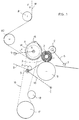
- W designates a web material, in particular paper, which is unwound from a large-sized roll, not shown, and, travelling in the direction of the arrow F, is suitably tensioned by rollers R1 and R2 and wound around a first winding roller A, to be rewound in rolls or logs 1, of a considerably smaller diameter, around a central core 2.
- the first winding roller A is associated with a second winding roller B, which defines therewith a gap 3, through which the cores 2 are inserted.
- the width of the gap 3 is constant during operation of the machine and not greater than the diameter of the core so that the latter enters the gap with slight forcing.
- One of the two rollers A, B, in the example shown the first winding roller A, is supported by a mobile arm 4, schematised in the figure, pivoted at 5, to adjust the width of the gap 3 to the diameter of the core 2 which is used.
- the group of three winding rollers is completed by a third roller C, also called a pressure roller, supported by an arm 6 movable around a fulcrum 7, according to a predetermined law of motion, to allow the roll 1 to be increased in diameter and discharged at the end of winding.
- a third roller C also called a pressure roller, supported by an arm 6 movable around a fulcrum 7, according to a predetermined law of motion, to allow the roll 1 to be increased in diameter and discharged at the end of winding.
- a feed slide 8 is provided for the cores 2 and a core inserting device comprising idler rollers 9 carried at the end of an arm 10 pivoted at 11.
- a rotating member 14 carrying a blade 15 protruding beyond the profile of the roller A is pivoted on the axis X of the first winding roller A.
- the member 15 has been called and will henceforth be called a blade, in that it causes severing of the web material, as will be explained below, but in fact it may not have, and preferably does not have, knife-type cutting edges.
- the rotating member 14 is driven in rotation in the same direction as the roller A, which is anticlockwise in the appended figures, and is motorized separately by means of a belt drive 16 actuated by a motorized wheel 17 and passing round a tensioning roller 18.
- actuating means can be provided for the rotating member 14, such as, for example, chains, gears and the like.
- the blade 15 has a concave shape toward the outside, substantially a very wide V shape, with the first leg, in the direction of rotation, longer than the other and less inclined with respect to the tangent to the winding roller A.
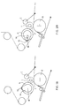
- Figure 1A illustrates the configuration of the machine during winding of the roll 1, with the blade 15 in the resting position, that is with the rotating member 14 at a standstill.
- the three rollers A, B, C all rotate at a constant and substantially the same speed, a speed which corresponds to the feeding speed of the web material.
- the blade 15 After an initial acceleration stage, the blade 15 reaches the same speed, or a very similar speed, as that of the web material W.
- the core inserting arm 10 begins to rise to bring a new core 2 into the gap between the two rollers A, B.
- the blade 15 can be advantageous for the blade 15 to have a high coefficient of friction, at least at the point of contact 15' with the web material W, so as to facilitate severing of the web material.
- the blade 15 can assume different configurations, for example with a continuous edge, serrated, or the like.
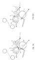
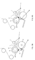
- FIG. 6A This situation is shown in Figure 6A, where the formed log has been expelled and a new log being formed is entering the winding space.
- the blade 15 is moving into the resting position and the core inserting arm 10 is going back to pick up a new core, to start a new winding cycle, and the three rollers A, B, C begin to rotate again at the same speed.
- the blade 15 made of a material with a high coefficient of friction, is advantageously given a convex profile toward the outside.
Abstract
Description
- The present invention relates to a peripheral rewinding machine and relative rewinding method for the production of rolls or logs of web material, such as paper and the like, on a tubular support or core.
- In a peripheral rewinding machine of the type to which the invention refers, the roll is wound around a tubular core which is set in rotation between a group of three rollers that act on the periphery of the roll being formed, and the speeds of which are kept constant and equal during the winding cycle.
- The group of three motorized rollers forms a space of variable size so that the three rollers are always in contact with the roll being formed, as the roll increases in diameter. Two of the three rollers are placed at a fixed distance, so as to define a gap, through which the core is inserted, and in which the web material travels, whilst the third roller or pressure roller is movable to allow the diameter of the roll to increase and the roll to be expelled at the end of winding.
- In these rewinding machines the so-called changeover stage is important, that is insertion of a new core in the winding space, accompanied by a special inserter, and discharge of the completed log, following severing of the web material.
- This severing is obtained in various ways according to the prior art, generally requiring sudden changes in the speed of two of the three winding rollers.
- According to some known methods, the speed change of said rollers alone, which is naturally of rather a large entity, causes tensioning and tearing of the web of paper following nipping thereof against the roller along which it is fed, nipping which can take place by means of a new core which is inserted in the winding space. After severing of the web of paper, entry of the new core into the winding space and discharge of the formed log take place through differences in speed between the two input rollers and the two output rollers, respectively.
- As stated previously, this method of severing the paper requires large variations in speed between the rollers, and in particular strong accelerations of the pressure roller, which cause stress on the structure of the machine. Moreover, such methods make it difficult to sever the web material on a same perforated line.
- Other systems use true cutting blades that cut the web at the end of winding and require complicated actuating mechanisms. Moreover, they are not very flexible in that they are tied to carrying out the cut on well-defined lengths of web material.
- The object of the invention is to eliminate the drawbacks of the solutions of the prior art, and therefore to provide a rewinding machine and a rewinding method that are reliable, simple to create and ensure precise cutting of the web material.
- This object is achieved with the rewinding machine according to the invention having the characteristics of appended
independent claim 1 and with the rewinding method having the characteristics of appendedindependent claim 8. - Preferred embodiments of the invention are apparent from the dependent claims.
- Substantially, according to the invention, a blade carried by a rotating member pivoted on the axis of the roller around which the web material is wound and rotating in the same direction as said roller is provided.
- The rotating member is actuated when the log is in the completion stage at a speed equal to or substantially similar to that of the web material, to be subsequently slowed or accelerated when it is inside the winding space, to cause tensioning and severing of the material. Normally severing of the material takes place along a line of perforation thereof.
- Further characteristics of the invention will be made clearer by the detailed description that follows, referring to a purely exemplary and therefore non-limiting embodiment thereof, illustrated in the appended drawings, in which:
- Figure 1 is a schematic side view of the basic elements of the rewinding machine according to the invention;
- Figures 1A to 6A are views like that in Figure 1, illustrating successive stages of the winding cycle according to a first embodiment of the invention;
- Figures 1B to 6B are views like that in Figure 1, illustrating successive stages of the winding cycle according to a second embodiment of the invention.
-
- With reference to said figures, for now in particular to Figure 1, which schematically illustrates a few more elements of the machine, a brief description of said elements will be made.
- In the description that follows reference will be made in the singular to the elements shown in the drawings, it nevertheless being obvious that many of them, such as the arms and levers, are disposed in pairs, at the two sides of the machine.
- In the appended figures, W designates a web material, in particular paper, which is unwound from a large-sized roll, not shown, and, travelling in the direction of the arrow F, is suitably tensioned by rollers R1 and R2 and wound around a first winding roller A, to be rewound in rolls or
logs 1, of a considerably smaller diameter, around acentral core 2. - The first winding roller A is associated with a second winding roller B, which defines therewith a
gap 3, through which thecores 2 are inserted. - The width of the
gap 3 is constant during operation of the machine and not greater than the diameter of the core so that the latter enters the gap with slight forcing. - One of the two rollers A, B, in the example shown the first winding roller A, is supported by a mobile arm 4, schematised in the figure, pivoted at 5, to adjust the width of the
gap 3 to the diameter of thecore 2 which is used. - The group of three winding rollers is completed by a third roller C, also called a pressure roller, supported by an
arm 6 movable around a fulcrum 7, according to a predetermined law of motion, to allow theroll 1 to be increased in diameter and discharged at the end of winding. - Upstream of the gap 3 a
feed slide 8 is provided for thecores 2 and a core inserting device comprisingidler rollers 9 carried at the end of anarm 10 pivoted at 11. Thearm 10, which in the appended figures has been schematised with a segment of straight line, in fact has, in a per se known manner, a beak shape so as to push thecore 2 into the winding space without interfering with the winding roller B. - A rotating
member 14 carrying ablade 15 protruding beyond the profile of the roller A is pivoted on the axis X of the first winding roller A. Themember 15 has been called and will henceforth be called a blade, in that it causes severing of the web material, as will be explained below, but in fact it may not have, and preferably does not have, knife-type cutting edges. - The rotating
member 14 is driven in rotation in the same direction as the roller A, which is anticlockwise in the appended figures, and is motorized separately by means of abelt drive 16 actuated by amotorized wheel 17 and passing round atensioning roller 18. Obviously other actuating means can be provided for the rotatingmember 14, such as, for example, chains, gears and the like. - Operation of the machine according to two different embodiments, shown respectively in Figures 1A to 6A and 1B to 6B will now be illustrated, using in both cases the same reference numerals to designate like or similar parts.
- In the embodiment according to Figures 1A to 6A the
blade 15 has a concave shape toward the outside, substantially a very wide V shape, with the first leg, in the direction of rotation, longer than the other and less inclined with respect to the tangent to the winding roller A. - Figure 1A illustrates the configuration of the machine during winding of the
roll 1, with theblade 15 in the resting position, that is with the rotatingmember 14 at a standstill. In this condition, the three rollers A, B, C all rotate at a constant and substantially the same speed, a speed which corresponds to the feeding speed of the web material. - In Figure 2A the machine is near the changeover, that is about at the end of winding of
roll 1, when said roll is about to be discharged and anew core 2 must be inserted. - In this stage the
blade 15, together with the rotatingmember 14 is set in rotation by themotorized wheel 17 and thebelt drive 16 in the same direction of rotation as roller A, indicated by the arrow F1 in the appended figures. - After an initial acceleration stage, the
blade 15 reaches the same speed, or a very similar speed, as that of the web material W. - In the stage illustrated in Figure 3A, the
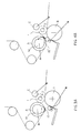
blade 15, which travels at substantially the same speed as that of the web material W, has slightly raised the material W from the profile of the winding roller A and is accompanying it into the winding space. Again in this stage, thecore inserting arm 10 begins to rise to bring anew core 2 into the gap between the two rollers A, B. - In Figure 4A the
log 1 is practically completed and severing of the web material is taking place. In this stage the pressure roller C has begun an acceleration stage, and the bottom roller B is possibly slowed, causing theroll 1 to move toward the outlet from the winding space. - At the same time, or with slight staggering with respect to the acceleration of the pressure roller C, the
blade 15 is slowed, so that the web material W has to slide on thecontact edge 15' of theblade 15. In this situation, a transverse line of perforation of the web material comes to pass on the point ofcontact 15' with theblade 15, and tensioning of the web material due to acceleration of the pressure roller C causes such a lengthening as to cause separation of the material at said line of perforation, as shown in Figure 5A. - It can be advantageous for the
blade 15 to have a high coefficient of friction, at least at the point ofcontact 15' with the web material W, so as to facilitate severing of the web material. - However, depending upon the types of material to be wound, the various types of perforations adopted or even the lack of perforations on the web material, the
blade 15 can assume different configurations, for example with a continuous edge, serrated, or the like. - Coming back to Figure 5A, it can be noted that a
new core 2, on which an adhesive has previously been spread, comes into contact with the already separated web material W, beginning to wind it on itself, thus starting formation of anew roll 1, which is moved into the winding space by a possible difference in speed between the rollers A and B, the latter having previously been decelerated. - This situation is shown in Figure 6A, where the formed log has been expelled and a new log being formed is entering the winding space. The
blade 15 is moving into the resting position and thecore inserting arm 10 is going back to pick up a new core, to start a new winding cycle, and the three rollers A, B, C begin to rotate again at the same speed. - In the embodiment illustrated in figures 1B to 6B the same series of stages is shown as in figures 1A to 6A of the first embodiment, therefore they will not be described in detail.
- The substantial difference of this second embodiment with respect to the first lies in the fact that the
blade 15 is accelerated instead of decelerated to cause separation of the web material W. - For this purpose, in this case the
blade 15, made of a material with a high coefficient of friction, is advantageously given a convex profile toward the outside. - In the situation in Figure 4B, the acceleration of the
blade 15 with the strong grip on the portion of web material W nipped by thenew core 2 against the upper winding roller A, causes a further stretching of the web material and thus severing along the line of perforation between the core being inserted and the blade. - Of course the invention is not limited to the particular embodiments previously described and illustrated in the appended drawings, but numerous changes of detail within the reach of a person skilled in the art can be made thereto, without thereby departing from the scope of the invention, as defined by the appended claims.
Claims (14)
- A peripheral rewinding machine for the production of logs (1) of web materials (W) on tubular cores (2), comprising a first winding roller (A), on which the web material (W) is wound, a second winding roller (B) defining with the first winding roller (A) a gap (3), through which the new core (2) is inserted, a third roller or pressure roller (C) mounted movably to allow the diameter of the log (1) to increase and the log to be discharged at the end of winding, means for severing the web material (W) at the end of winding and means for inserting a new core (2), characterized in that said means for severing the web material (W) comprise a blade (15) carried by a rotating member (14) pivoted on the axis (X) of said first winding roller (A) and protruding from the profile of said roller (A) and in that actuating means are provided such as to cause the blade (15) to rotate at different speeds in the same direction of rotation as said winding roller (A), such as to impart a change in speed to the blade when the latter is in contact with the web material (W) in the winding space bed defined by the three rollers (A, B, C).
- A rewinding machine according to claim 1, characterized in that said blade (15) has at least one coating of a material with a high coefficient of friction, such as to provide a strong grip with the web material (W).
- A rewinding machine according to claim 1 or 2, characterized in that said actuating means for the blade (15) give the blade a deceleration when it is in contact with the web material (W) in the winding space, so as to cause severing of the web material (W) between the point of contact of the web material with the blade and the log in the expulsion stage.
- A rewinding machine according to claim 1 or 2, characterized in that said actuating means for the blade give the blade an acceleration when it is in contact with the web material (W) in the winding space, so as to cause severing of the web material between the point of nipping of the web material caused by the contact of a new core (2) with the winding roller (A) and the point of contact (15') of the blade with the web material (W).
- A rewinding machine according to any one of the preceding claims, characterized in that said web material (W) comprises predefined transverse lines of perforation along which severing of the web material takes place.
- A rewinding machine according to any one of the preceding claims, characterized in that means are provided to accelerate said pressure roller (C) and possibly to decelerate said second winding roller (B) during severing of the web material (W).
- A rewinding machine according to any one of the preceding claims, characterized in that said means for driving the blade (15) are independent from the drive means of said first winding roller (A).
- A method for producing logs (1) of web materials, such as paper and the like, in which the web material (W) is fed along a first winding roller (A) and wound around a tubular core (2) set in rotation in a winding space defined by said first winding roller (A), a second winding roller (B) and a pressure roller (C), and in which said web material (W) is severed at the end of winding of a log (1), characterized in that said severing takes place by means of a blade (15) carried by a rotating member (14) pivoted on the axis (X) of said first winding roller (A) and rotating at different speeds, said blade (15) protruding from the profile of said first winding roller (A) and undergoing a change in speed when it is in contact with the web material (W) in said winding space.
- A method according to claim 8, characterized in that said blade (15) has a high coefficient of friction, so as to cause a strong grip on said web material (W).
- A method according to claim 8 or 9, characterized in that said blade (15) undergoes a deceleration when it is in contact with said web material (W) in the winding space, so a to cause severing of the web material between the point of contact of the blade with the web material and the log (1) in the expulsion stage.
- A method according to claim 8 or 9, characterized in that said blade (15) undergoes an acceleration when it is in contact with said web material (W) in the winding space so as to cause severing of the web material between the point of nipping of the web material determined by the contact of a new core with said first winding roller (A), and the point of contact (15') of the blade (15) with the web material.
- A method according to any one of claims 8 to 11, characterized in that said severing of the web material takes place along one of the predefined transverse lines of perforation on the web material.
- A method according to any one of claims 8 to 12, characterized in that an acceleration of the pressure roller (C) and a possible deceleration of a second winding roller (B) are provided during the stage of severing of said web material (W).
- A method according to any one of claims 8 to 13, characterized in that said blade (15) is actuated independently from said first winding roller (A).
Applications Claiming Priority (2)
| Application Number | Priority Date | Filing Date | Title |
|---|---|---|---|
| IT2000MI002399A IT1319321B1 (en) | 2000-11-07 | 2000-11-07 | PERIPHERAL REWINDING MACHINE AND METHOD FOR THE PRODUCTION OF LOGS OF SHEET MATERIALS |
| ITMI002399 | 2000-11-07 |
Publications (3)
| Publication Number | Publication Date |
|---|---|
| EP1205414A2 true EP1205414A2 (en) | 2002-05-15 |
| EP1205414A3 EP1205414A3 (en) | 2004-05-12 |
| EP1205414B1 EP1205414B1 (en) | 2006-11-08 |
Family
ID=11446088
Family Applications (1)
| Application Number | Title | Priority Date | Filing Date |
|---|---|---|---|
| EP01122438A Expired - Lifetime EP1205414B1 (en) | 2000-11-07 | 2001-09-20 | Peripheral rewinding machine and method for producing logs of web material |
Country Status (8)
| Country | Link |
|---|---|
| EP (1) | EP1205414B1 (en) |
| JP (1) | JP2002205853A (en) |
| AT (1) | ATE344774T1 (en) |
| CA (1) | CA2357336A1 (en) |
| DE (1) | DE60124366T2 (en) |
| ES (1) | ES2275597T3 (en) |
| IT (1) | IT1319321B1 (en) |
| MX (1) | MXPA01011253A (en) |
Cited By (2)
| Publication number | Priority date | Publication date | Assignee | Title |
|---|---|---|---|---|
| ITFI20100025A1 (en) * | 2010-02-23 | 2011-08-24 | Perini Fabio Spa | "REWINDING MACHINE AND RELATIVE WINDING METHOD" |
| IT201600091411A1 (en) * | 2016-09-09 | 2018-03-09 | Gambini Spa | DEVICE FOR REWINDING AND FORMATION OF A PAPER ROLL AND RELATIVE METHOD. |
Families Citing this family (2)
| Publication number | Priority date | Publication date | Assignee | Title |
|---|---|---|---|---|
| JP5963713B2 (en) * | 2013-06-21 | 2016-08-03 | 住友重機械モダン株式会社 | Web cutting equipment |
| KR102394290B1 (en) * | 2014-07-31 | 2022-05-03 | 파비오 페리니 에스. 피. 에이. | Rewinding machine and method for producing logs of web material |
Citations (3)
| Publication number | Priority date | Publication date | Assignee | Title |
|---|---|---|---|---|
| FR2547802A1 (en) * | 1983-06-13 | 1984-12-28 | Jagenberg Ag | Method for cutting the webs (bands, strips) in winders |
| EP0716997A2 (en) * | 1994-12-13 | 1996-06-19 | Valmet Corporation | Method and assembly for cutting a web |
| EP0853060A1 (en) * | 1997-01-10 | 1998-07-15 | Italconverting srl | Machine and method for producing logs of sheet material |
-
2000
- 2000-11-07 IT IT2000MI002399A patent/IT1319321B1/en active
-
2001
- 2001-09-14 CA CA002357336A patent/CA2357336A1/en not_active Abandoned
- 2001-09-20 EP EP01122438A patent/EP1205414B1/en not_active Expired - Lifetime
- 2001-09-20 DE DE60124366T patent/DE60124366T2/en not_active Expired - Fee Related
- 2001-09-20 AT AT01122438T patent/ATE344774T1/en not_active IP Right Cessation
- 2001-09-20 ES ES01122438T patent/ES2275597T3/en not_active Expired - Lifetime
- 2001-11-06 JP JP2001340929A patent/JP2002205853A/en active Pending
- 2001-11-06 MX MXPA01011253A patent/MXPA01011253A/en active IP Right Grant
Patent Citations (3)
| Publication number | Priority date | Publication date | Assignee | Title |
|---|---|---|---|---|
| FR2547802A1 (en) * | 1983-06-13 | 1984-12-28 | Jagenberg Ag | Method for cutting the webs (bands, strips) in winders |
| EP0716997A2 (en) * | 1994-12-13 | 1996-06-19 | Valmet Corporation | Method and assembly for cutting a web |
| EP0853060A1 (en) * | 1997-01-10 | 1998-07-15 | Italconverting srl | Machine and method for producing logs of sheet material |
Cited By (6)
| Publication number | Priority date | Publication date | Assignee | Title |
|---|---|---|---|---|
| ITFI20100025A1 (en) * | 2010-02-23 | 2011-08-24 | Perini Fabio Spa | "REWINDING MACHINE AND RELATIVE WINDING METHOD" |
| WO2011104737A1 (en) * | 2010-02-23 | 2011-09-01 | Fabio Perini S.P.A. | Rewinding machine and winding method |
| US9079737B2 (en) | 2010-02-23 | 2015-07-14 | Fabio Perini S.P.A. | Rewinding machine and winding method |
| IT201600091411A1 (en) * | 2016-09-09 | 2018-03-09 | Gambini Spa | DEVICE FOR REWINDING AND FORMATION OF A PAPER ROLL AND RELATIVE METHOD. |
| EP3293133A1 (en) * | 2016-09-09 | 2018-03-14 | GAMBINI S.p.A. | Device for rewinding and forming a paper roll and related method |
| US10562725B2 (en) | 2016-09-09 | 2020-02-18 | GAMBINI S.p.A. | Device for rewinding and forming a paper roll and related method |
Also Published As
| Publication number | Publication date |
|---|---|
| IT1319321B1 (en) | 2003-10-10 |
| ATE344774T1 (en) | 2006-11-15 |
| MXPA01011253A (en) | 2004-06-25 |
| JP2002205853A (en) | 2002-07-23 |
| DE60124366T2 (en) | 2007-09-06 |
| ITMI20002399A1 (en) | 2002-05-07 |
| CA2357336A1 (en) | 2002-05-07 |
| EP1205414B1 (en) | 2006-11-08 |
| DE60124366D1 (en) | 2006-12-21 |
| ES2275597T3 (en) | 2007-06-16 |
| EP1205414A3 (en) | 2004-05-12 |
Similar Documents
| Publication | Publication Date | Title |
|---|---|---|
| KR100202226B1 (en) | Rewinding machine and method for the formation of logs of web material with means for severing the web material | |
| JP3341301B2 (en) | Method and machine for forming rolls or logs of web material | |
| KR101760544B1 (en) | Rewinding machine and method for the production of rolls of web material | |
| US6648266B1 (en) | Rewinding machine and method for the formation of logs of web material with means for severing the web material | |
| US5639046A (en) | Machine and method for the formation of coreless logs of web material | |
| CA2115497C (en) | Rewinding machine for coreless winding of a log of web material with a surface for supporting the log in the process of winding | |
| US7887003B2 (en) | Machine and method for the production of rolls of weblike material together with a winding core and roll thus obtained | |
| EP0853060B1 (en) | Machine and method for producing logs of sheet material | |
| US10457513B2 (en) | Rewinding machine and method for producing rolls of web material | |
| US6659387B2 (en) | Peripheral rewinding machine and method for producing logs of web material | |
| JPH0158098B2 (en) | ||
| US20030010863A1 (en) | Core feeding method in a rewinding machine for making logs of sheet material | |
| EP1205414B1 (en) | Peripheral rewinding machine and method for producing logs of web material | |
| JPH0192155A (en) | Continuously operating type manufacturing device for web roll | |
| CA2100797C (en) | Machine and method for the formation of coreless logs of web material | |
| JPH0530043Y2 (en) | ||
| JPH0530042Y2 (en) |
Legal Events
| Date | Code | Title | Description |
|---|---|---|---|
| PUAI | Public reference made under article 153(3) epc to a published international application that has entered the european phase |
Free format text: ORIGINAL CODE: 0009012 |
|
| AK | Designated contracting states |
Kind code of ref document: A2 Designated state(s): AT BE CH CY DE DK ES FI FR GB GR IE IT LI LU MC NL PT SE TR |
|
| AX | Request for extension of the european patent |
Free format text: AL;LT;LV;MK;RO;SI |
|
| RAP1 | Party data changed (applicant data changed or rights of an application transferred) |
Owner name: PAPER CONVERTING MACHINE COMPANY ITALIA S.P.A. |
|
| PUAL | Search report despatched |
Free format text: ORIGINAL CODE: 0009013 |
|
| AK | Designated contracting states |
Kind code of ref document: A3 Designated state(s): AT BE CH CY DE DK ES FI FR GB GR IE IT LI LU MC NL PT SE TR |
|
| AX | Request for extension of the european patent |
Extension state: AL LT LV MK RO SI |
|
| 17P | Request for examination filed |
Effective date: 20041018 |
|
| AKX | Designation fees paid |
Designated state(s): AT BE CH CY DE DK ES FI FR GB GR IE IT LI LU MC NL PT SE TR |
|
| GRAP | Despatch of communication of intention to grant a patent |
Free format text: ORIGINAL CODE: EPIDOSNIGR1 |
|
| GRAS | Grant fee paid |
Free format text: ORIGINAL CODE: EPIDOSNIGR3 |
|
| GRAA | (expected) grant |
Free format text: ORIGINAL CODE: 0009210 |
|
| AK | Designated contracting states |
Kind code of ref document: B1 Designated state(s): AT BE CH CY DE DK ES FI FR GB GR IE IT LI LU MC NL PT SE TR |
|
| PG25 | Lapsed in a contracting state [announced via postgrant information from national office to epo] |
Ref country code: BE Free format text: LAPSE BECAUSE OF FAILURE TO SUBMIT A TRANSLATION OF THE DESCRIPTION OR TO PAY THE FEE WITHIN THE PRESCRIBED TIME-LIMIT Effective date: 20061108 Ref country code: LI Free format text: LAPSE BECAUSE OF FAILURE TO SUBMIT A TRANSLATION OF THE DESCRIPTION OR TO PAY THE FEE WITHIN THE PRESCRIBED TIME-LIMIT Effective date: 20061108 Ref country code: NL Free format text: LAPSE BECAUSE OF FAILURE TO SUBMIT A TRANSLATION OF THE DESCRIPTION OR TO PAY THE FEE WITHIN THE PRESCRIBED TIME-LIMIT Effective date: 20061108 Ref country code: AT Free format text: LAPSE BECAUSE OF FAILURE TO SUBMIT A TRANSLATION OF THE DESCRIPTION OR TO PAY THE FEE WITHIN THE PRESCRIBED TIME-LIMIT Effective date: 20061108 Ref country code: CH Free format text: LAPSE BECAUSE OF FAILURE TO SUBMIT A TRANSLATION OF THE DESCRIPTION OR TO PAY THE FEE WITHIN THE PRESCRIBED TIME-LIMIT Effective date: 20061108 Ref country code: FI Free format text: LAPSE BECAUSE OF FAILURE TO SUBMIT A TRANSLATION OF THE DESCRIPTION OR TO PAY THE FEE WITHIN THE PRESCRIBED TIME-LIMIT Effective date: 20061108 |
|
| REG | Reference to a national code |
Ref country code: GB Ref legal event code: FG4D |
|
| REG | Reference to a national code |
Ref country code: CH Ref legal event code: EP |
|
| REG | Reference to a national code |
Ref country code: IE Ref legal event code: FG4D |
|
| REF | Corresponds to: |
Ref document number: 60124366 Country of ref document: DE Date of ref document: 20061221 Kind code of ref document: P |
|
| PG25 | Lapsed in a contracting state [announced via postgrant information from national office to epo] |
Ref country code: SE Free format text: LAPSE BECAUSE OF FAILURE TO SUBMIT A TRANSLATION OF THE DESCRIPTION OR TO PAY THE FEE WITHIN THE PRESCRIBED TIME-LIMIT Effective date: 20070208 Ref country code: DK Free format text: LAPSE BECAUSE OF FAILURE TO SUBMIT A TRANSLATION OF THE DESCRIPTION OR TO PAY THE FEE WITHIN THE PRESCRIBED TIME-LIMIT Effective date: 20070208 |
|
| PG25 | Lapsed in a contracting state [announced via postgrant information from national office to epo] |
Ref country code: PT Free format text: LAPSE BECAUSE OF FAILURE TO SUBMIT A TRANSLATION OF THE DESCRIPTION OR TO PAY THE FEE WITHIN THE PRESCRIBED TIME-LIMIT Effective date: 20070409 |
|
| NLV1 | Nl: lapsed or annulled due to failure to fulfill the requirements of art. 29p and 29m of the patents act | ||
| REG | Reference to a national code |
Ref country code: CH Ref legal event code: PL |
|
| ET | Fr: translation filed | ||
| REG | Reference to a national code |
Ref country code: ES Ref legal event code: FG2A Ref document number: 2275597 Country of ref document: ES Kind code of ref document: T3 |
|
| PLBE | No opposition filed within time limit |
Free format text: ORIGINAL CODE: 0009261 |
|
| STAA | Information on the status of an ep patent application or granted ep patent |
Free format text: STATUS: NO OPPOSITION FILED WITHIN TIME LIMIT |
|
| PGFP | Annual fee paid to national office [announced via postgrant information from national office to epo] |
Ref country code: ES Payment date: 20070920 Year of fee payment: 7 |
|
| 26N | No opposition filed |
Effective date: 20070809 |
|
| PGFP | Annual fee paid to national office [announced via postgrant information from national office to epo] |
Ref country code: GB Payment date: 20070907 Year of fee payment: 7 |
|
| PGFP | Annual fee paid to national office [announced via postgrant information from national office to epo] |
Ref country code: DE Payment date: 20070928 Year of fee payment: 7 |
|
| PG25 | Lapsed in a contracting state [announced via postgrant information from national office to epo] |
Ref country code: GR Free format text: LAPSE BECAUSE OF FAILURE TO SUBMIT A TRANSLATION OF THE DESCRIPTION OR TO PAY THE FEE WITHIN THE PRESCRIBED TIME-LIMIT Effective date: 20070209 Ref country code: MC Free format text: LAPSE BECAUSE OF NON-PAYMENT OF DUE FEES Effective date: 20070930 |
|
| PGFP | Annual fee paid to national office [announced via postgrant information from national office to epo] |
Ref country code: FR Payment date: 20070927 Year of fee payment: 7 |
|
| PG25 | Lapsed in a contracting state [announced via postgrant information from national office to epo] |
Ref country code: IE Free format text: LAPSE BECAUSE OF NON-PAYMENT OF DUE FEES Effective date: 20070920 |
|
| GBPC | Gb: european patent ceased through non-payment of renewal fee |
Effective date: 20080920 |
|
| REG | Reference to a national code |
Ref country code: FR Ref legal event code: ST Effective date: 20090529 |
|
| PG25 | Lapsed in a contracting state [announced via postgrant information from national office to epo] |
Ref country code: DE Free format text: LAPSE BECAUSE OF NON-PAYMENT OF DUE FEES Effective date: 20090401 Ref country code: IT Free format text: LAPSE BECAUSE OF NON-PAYMENT OF DUE FEES Effective date: 20080920 Ref country code: CY Free format text: LAPSE BECAUSE OF FAILURE TO SUBMIT A TRANSLATION OF THE DESCRIPTION OR TO PAY THE FEE WITHIN THE PRESCRIBED TIME-LIMIT Effective date: 20061108 Ref country code: LU Free format text: LAPSE BECAUSE OF NON-PAYMENT OF DUE FEES Effective date: 20070920 |
|
| PG25 | Lapsed in a contracting state [announced via postgrant information from national office to epo] |
Ref country code: TR Free format text: LAPSE BECAUSE OF FAILURE TO SUBMIT A TRANSLATION OF THE DESCRIPTION OR TO PAY THE FEE WITHIN THE PRESCRIBED TIME-LIMIT Effective date: 20061108 |
|
| PG25 | Lapsed in a contracting state [announced via postgrant information from national office to epo] |
Ref country code: FR Free format text: LAPSE BECAUSE OF NON-PAYMENT OF DUE FEES Effective date: 20080930 |
|
| REG | Reference to a national code |
Ref country code: ES Ref legal event code: FD2A Effective date: 20080922 |
|
| PG25 | Lapsed in a contracting state [announced via postgrant information from national office to epo] |
Ref country code: GB Free format text: LAPSE BECAUSE OF NON-PAYMENT OF DUE FEES Effective date: 20080920 |
|
| PG25 | Lapsed in a contracting state [announced via postgrant information from national office to epo] |
Ref country code: ES Free format text: LAPSE BECAUSE OF NON-PAYMENT OF DUE FEES Effective date: 20080922 |
|
| PGRI | Patent reinstated in contracting state [announced from national office to epo] |
Ref country code: IT Effective date: 20110101 |
|
| PGFP | Annual fee paid to national office [announced via postgrant information from national office to epo] |
Ref country code: IT Payment date: 20200908 Year of fee payment: 20 |