EP1205371A2 - Motor vehicle steering system - Google Patents
Motor vehicle steering system Download PDFInfo
- Publication number
- EP1205371A2 EP1205371A2 EP01126850A EP01126850A EP1205371A2 EP 1205371 A2 EP1205371 A2 EP 1205371A2 EP 01126850 A EP01126850 A EP 01126850A EP 01126850 A EP01126850 A EP 01126850A EP 1205371 A2 EP1205371 A2 EP 1205371A2
- Authority
- EP
- European Patent Office
- Prior art keywords
- steering
- actuator
- force
- motor vehicle
- counter
- Prior art date
- Legal status (The legal status is an assumption and is not a legal conclusion. Google has not performed a legal analysis and makes no representation as to the accuracy of the status listed.)
- Granted
Links
Images


Classifications
-
- B—PERFORMING OPERATIONS; TRANSPORTING
- B62—LAND VEHICLES FOR TRAVELLING OTHERWISE THAN ON RAILS
- B62D—MOTOR VEHICLES; TRAILERS
- B62D5/00—Power-assisted or power-driven steering
- B62D5/001—Mechanical components or aspects of steer-by-wire systems, not otherwise provided for in this maingroup
- B62D5/005—Mechanical components or aspects of steer-by-wire systems, not otherwise provided for in this maingroup means for generating torque on steering wheel or input member, e.g. feedback
- B62D5/006—Mechanical components or aspects of steer-by-wire systems, not otherwise provided for in this maingroup means for generating torque on steering wheel or input member, e.g. feedback power actuated
-
- B—PERFORMING OPERATIONS; TRANSPORTING
- B62—LAND VEHICLES FOR TRAVELLING OTHERWISE THAN ON RAILS
- B62D—MOTOR VEHICLES; TRAILERS
- B62D5/00—Power-assisted or power-driven steering
- B62D5/001—Mechanical components or aspects of steer-by-wire systems, not otherwise provided for in this maingroup
- B62D5/003—Backup systems, e.g. for manual steering
Definitions
- the present invention relates to a motor vehicle steering system which is adapted to turn steerable vehicle wheels on the basis of the operation of an operation member such as a steering wheel.
- a steering system for a motor vehicle (so-called steer-by-wire system) has been proposed, which has no mechanical coupling between a steering wheel and a steering mechanism for turning steerable vehicle wheels, and is adapted to detect the direction and degree of the operation of the steering wheel and apply a driving force from a steering actuator such as an electric motor to the steering mechanism on the basis of the result of the detection.
- a steering actuator such as an electric motor
- This arrangement makes it possible to flexibly change the ratio (gear ratio) of the degree of the rotation of the steering wheel to the degree of the turning of the steerable vehicle wheels depending on the traveling state of the vehicle for improvement of the maneuverability of the motor vehicle.
- the aforesaid arrangement advantageously prevents upward thrust of the steering wheel in the event of the collision of the motor vehicle, and allows for more flexible placement of the steering wheel.
- the steer-by-wire system Since the steer-by-wire system has no mechanical coupling between the steering wheel and the steering mechanism, it is important to give a fail-safe consideration to a steering drive system. To this end, it is proposed to provide a clutch between the steering wheel and the steering mechanism for engagement and disengagement therebetween, whereby a mechanical coupling is established between the steering wheel and the steering mechanism with the clutch brought into engagement in the event of malfunction of the system.
- the motor vehicle steering system comprises: an operation member for steering a motor vehicle; a steering mechanism for turning steerable wheels of the motor vehicle; a first actuator and a second actuator each operative to apply a driving force to the steering mechanism; and a steering control section which, when the first and second actuators operate normally, causes at least one of the first and second actuators to apply the driving force to the steering mechanism and, when one of the first and second actuators malfunctions, causes the other normal actuator to apply the driving force to the steering mechanism.
- a motor vehicle steering system which comprises: an operation member for steering a motor vehicle; a steering mechanism for turning steerable wheels of the motor vehicle; a primary steering actuator and a secondary steering actuator coupled to the steering mechanism; a clutch mechanism operative to mechanically engage and disengage the operation member with respect to the steering mechanism; and a steering control section which, when the primary steering actuator and the secondary steering actuator operate normally, brings the clutch mechanism into a disengaged state to cause the primary steering actuator and the secondary steering actuator to generate a driving force for driving the steering mechanism and, when one of the primary steering actuator and the secondary steering actuator malfunctions, brings the clutch mechanism into an engaged state to cause the other normal steering actuator to generate a steering assist force according to operation of the operation member.
- the driving force is applied to the steering mechanism from both of the primary steering actuator and the secondary steering actuator. Even if the primary steering actuator and the secondary steering actuator each have a relatively small maximum output, the driving force can sufficiently be applied to the steering mechanism to properly perform a steering operation.
- the clutch mechanism If one of the primary steering actuator and the secondary steering actuator malfunctions, the clutch mechanism is brought into the engaged state, and the other normal steering actuator is controlled as a source of the steering assist force.
- the normal steering actuator applies the steering assist force to the steering mechanism according to the operation of the operation member. Therefore, the operation member can easily be operated even after the engagement of the clutch, allowing for a practical fail-safe steering operation.
- the motor vehicle steering system may further comprise a counter-force actuator for applying an operation reaction force to the operation member.
- the steering control section is preferably adapted to cause the counter-force actuator to generate an additional steering assist force according to the operation of the operation member when one of the primary steering actuator and the secondary steering actuator malfunctions.
- the counter-force actuator is also controlled as the source of the steering assist force if the primary steering actuator or the secondary steering actuator malfunctions.
- a further greater steering assist force can be applied to the steering mechanism, so that the operation member can more easily be operated after the engagement of the clutch mechanism.
- the steering control section is adapted to bring the clutch mechanism into the engaged state to cause the primary steering actuator and the secondary steering actuator to generate the steering assist force according to the operation of the operation member when the counter-force actuator malfunctions.
- the clutch mechanism is brought into the engaged state, and the primary steering actuator and the secondary steering actuator are controlled as the source of the steering assist force if the counter-force actuator malfunctions. Therefore, the operation member (e.g., steering wheel) can easily be operated, allowing for a practical fail-safe steering operation.
- the operation member e.g., steering wheel
- a motor vehicle steering system which comprises : an operation member for steering a motor vehicle; a steering mechanism for turning steerable wheels of the motor vehicle; a primary steering actuator and a secondary steering actuator coupled to the steering mechanism and having substantially the same maximum output; and steering control means which, when the primary steering actuator and the secondary steering actuator operate normally, causes the primary steering actuator and the secondary steering actuator to generate a driving force for driving the steering mechanism and, when one of the primary steering actuator and the secondary steering actuator malfunctions, causes the other normal steering actuator to generate the driving force for driving the steering mechanism.
- the driving force is applied to the steering mechanism from both of the primary steering actuator and the secondary steering actuator. Therefore, the maximum outputs of the primary steering actuator and the secondary steering actuator can each be set at a smaller level.
- the primary steering actuator and the secondary steering actuator preferably each have a maximum output which is 60% to 70% of an output sufficient to drive the steering mechanism.
- the driving force can sufficiently be applied to the steering mechanism to properly perform the steering operation, when the primary steering actuator and the secondary steering actuator operate normally. Even if only one of the primary steering actuator and the secondary steering actuator operates normally, a driving force sufficient to maintain the direction of the steerable vehicle wheels can be applied to the steering mechanism.
- a motor vehicle steering system which comprises: an operation member for steering a motor vehicle; a steering mechanism for turning steerable wheels of the motor vehicle; a steering actuator coupled to the steering mechanism; a clutch mechanism operative to mechanically engage and disengage the operation member with respect to the steering mechanism; a counter-force actuator for applying an operation reaction force to the operation member; and a steering control section which, when the steering actuator operates normally, brings the clutch mechanism into a disengaged state to cause the steering actuator to generate a driving force for driving the steering mechanism and, when the steering actuator malfunctions, brings the clutch mechanism into an engaged state to cause the counter-force actuator to generate a steering assist force according to operation of the operation member.
- the clutch mechanism is brought into the engaged state and the counter-force actuator is controlled as a source of the steering assist force, if the steering actuator malfunctions.
- the counter-force actuator applies the steering assist force to the steering mechanism according to the operation of the operation member. Therefore, the operation member can easily be operated after the engagement of the clutch mechanism, allowing for a practical fail-safe steering operation.
- Fig. 1 is a conceptual diagram for explaining the basic construction of a steering system for a motor vehicle in accordance with one embodiment of the present invention.
- the motor vehicle steering system includes a steering mechanism 10 for causing a pair of steer able vehicle wheels (typically, front wheels) W, W to perform a steering operation, a steering wheel 30 to be brought into or out of mechanical engagement with the steering mechanism 10 via a clutch 20, and a counter-force actuator 40 for applying a reaction force to the steering wheel 30.
- a steering mechanism 10 for causing a pair of steer able vehicle wheels (typically, front wheels) W, W to perform a steering operation, a steering wheel 30 to be brought into or out of mechanical engagement with the steering mechanism 10 via a clutch 20, and a counter-force actuator 40 for applying a reaction force to the steering wheel 30.
- the motor vehicle steering system has a dual steering drive system including a primary steering drive system 50M and a secondary steering drive system 50S for driving the steering mechanism 10.
- the primary steering drive system 50M includes a primary steering actuator 51M, and a primary rotation angle sensor 52M for detecting a rotation angle of the primary steering actuator 51M.
- the secondary steering drive system 50S includes a secondary steering actuator 51S, and a secondary rotation angle sensor 52S for detecting a rotation angle of the secondary steering actuator 51S.
- the primary steering actuator 51M and the secondary steering actuator 51S each comprise an electric motor, for example, and have substantially the same maximum output which is equal to 60% to 70% of an output sufficient for the primary steering actuator 51M or the secondary steering actuator 51S alone to drive the steering mechanism 10.
- the steering mechanism 10 includes a steering shaft 11 extending transversely of a body of the motor vehicle, and knuckle arms 13, 13 respectively coupled to opposite ends of the steering shaft 11 via tie rods 12, 12 for supporting the steerable vehicle wheels W, W.
- the steering shaft 11 is supported in a housing 14 in an axially slidable manner, and the primary steering actuator 51M is incorporated in the midst of the steering shaft 11 in a coaxial relation.
- a rack gear 11a is provided as a part of the steering shaft 11, and meshed with a pinion gear 22 provided at a distal end of a shaft 21 coupled to one side of the clutch 20.
- the shaft 21 is coupled to the secondary steering actuator 51S, so that a driving force generated by the secondary steering actuator 51S is inputted to the shaft 21.
- a shaft 23 coupled to the other side of the clutch 20 is coupled to the steering wheel 30. If the clutch 20 is in an engaged state, therefore, a steering torque applied to the steering wheel 30 is mechanically transmitted to the steering shaft 11 via the shaft 23, the clutch 20, the shaft 21, the pinion gear 22 and the rack gear 11a.
- the counter-force actuator 40 comprises an electricmotor (e.g., three-phase brushless motor) which has a rotation shaft defined by the shaft 23 connecting the clutch 20 to the steering wheel 30 and a casing fixed to an appropriate portion of the vehicle body.
- the counter-force actuator 40 is provided with a torque sensor 41 for detecting a steering torque inputted from the steering wheel 30, and an operation angle sensor 42 for detecting an operation angle of the steering wheel 30.
- the clutch 20, the counter-force actuator 40, the primary steering actuator 51M and the secondary steering actuator 51S are controlled by a steering controlling section 60 which comprises a microprocessor and the like. More specifically, detection signals of the steering angle sensor 42, the primary rotation angle sensor 52M and the secondary rotation angle sensor 52S are inputted to the steering controlling section 60.
- a steering position sensor 15 for detecting an axial position of the steering shaft 11 is provided in association with the steering shaft 11, and a detection signal of the steering position sensor 15 is also inputted to the steering controlling section 60. Further, a detection signal of a vehicle speed sensor 70 for detecting a vehicle speed is inputted to the steering controlling section 60.
- the vehicle speed sensor 70 may comprise, for example, a vehicle wheel speed sensor for detecting a rotation speed of each vehicle wheel.
- the steering controlling section 60 applies control signals to driver circuits 24, 43, 53M, 53S for driving the clutch 20, the counter-force actuator 40, the primary steering actuator 51M and the secondary steering actuator 51S, respectively, on the basis of the signals inputted from the respective sensors.
- Fig. 2 is a flow chart for explaining a process to be performed by the steering controlling section 60.
- the steering controlling section 60 constantly checks if the primary steering actuator 51M, the secondary steering actuator 51S and the counter-force actuator 40 each operate normally, i.e., if any of the primary steering actuator 51M, the secondary steering actuator 51S and the counter-force actuator 40 malfunctions (Step S1, S2).
- the steering controlling section 60 controls the primary steering actuator 51M and the secondary steering actuator 51S for driving thereof (Step S3).
- the steering controlling section 60 has a VGR (variable gear ratio) function, and is adapted to set the ratio (gear ratio) of the degree of the rotation of the steering wheel 30 to the degree of the turning of the steerable vehicle wheels W, W according to the traveling state of the motor vehicle.
- the steering controlling section 60 further sets voltage command values for the primary steering actuator 51M and the secondary steering actuator 51S on the basis of the gear ratio thus set and the degree of the operation of the steering wheel 30, and apply control signals corresponding to the respective voltage command values to the driver circuits 53M, 53S.
- torques are respectively outputted from the primary steering actuator 51M and the secondary steering actuator 51S for sliding the steering shaft 11 in a direction corresponding to the direction of the operation of the steering wheel 30, whereby the steering operation is properly performed according to the traveling state of the motor vehicle and the operation of the steering wheel 30.
- the steering controlling section 60 deactuates the VGR function (Step S4), and controls the other normal steering actuator to adjust the position of the steerable vehicle wheels W, W so that the rotation angle of the steering wheel 30 and the steering angle of the steerable vehicle wheels W, W are brought into a proper relationship (i.e., a relationship where the neutral point of the steering wheel 30 coincides with the neutral point of the steerable vehicle wheels W, W).
- a proper relationship i.e., a relationship where the neutral point of the steering wheel 30 coincides with the neutral point of the steerable vehicle wheels W, W.
- the engagement of the clutch 20 establishes the mechanical coupling between the steering mechanism 10 and the steering wheel 30 and, thereafter, the motor vehicle steering system functions as a power steering system employing the normal steering actuator (the primary steering actuator 51M or the secondary steering actuator 51S) and the counter-force actuator 40 as a source of a steering assist force .
- the steering controlling section 60 After the engagement of the clutch 20, the steering controlling section 60 generates a steering actuator PWM (pulse width modulation) control signal and a counter-force actuator PWM control signal according to the operation angle of the steering wheel 30 (steering wheel angle), and inputs these PWM control signals to the driver circuits of the normal steering actuator and the counter-force actuator 40 so as to cause the normal steering actuator and the counter-force actuator 40 to generate the steering assist force (Steps S7, S8).
- the steering assist force is properly generated by the normal steering actuator and the counter-force actuator 40, whereby a steering assist operation can properly be performed according to the operation of the steering wheel 30.
- the steering controlling section 60 first stops the driving of the counter-force actuator 40 (Step 39), and then deactuates the VGR function (Step S10).
- the steering controlling section 60 controls the normal steering actuator to adjust the position of the steerable vehicle wheels W, W so that the rotation angle of the steering wheel 30 and the steering angle of the steerable vehicle wheels W, W are brought into the proper relationship, and then establishes the engagement of the clutch 20 (Step S11).
- the steering mechanism 10 and the steering wheel 30 are mechanically coupled to each other, so that the motor vehicle steering system functions as a power steering system employing the primary steering actuator 51M and the secondary steering actuator 51S as the source of the steering assist force. That is, after the engagement of the clutch 20, the steering controlling section 60 generates a primary steering actuator PWM control signal and a secondary steering actuator PWM control signal according to the operation angle of the steering wheel 30 (steering wheel angle) , and inputs these PWM control signals to the driver circuits 53M and 53S of the primary steering actuator 51M and the secondary steering actuator 51S so as to cause the primary steering actuator 51M and the secondary steering actuator 51S to generate the steering assist force (Step S12).
- the steering assist force is properly generated by the primary steering actuator 51M and the secondary steering actuator 51S, whereby the steering assist operation can properly be performed according to the operation of the steering wheel 30.
- the steering mechanism 10 is driven by both of the primary steering system 50M and the secondary steering system 50S when the counter-force actuator 40, the primary steering actuator 51M and the secondary steering actuator 51S operate normally. Even if the primary steering actuator 51M and the secondary steering actuator 51S each have a relatively small maximum output, therefore, the driving force can sufficiently be applied to the steering mechanism 10, so that the steering operation can properly be performed.
- the engagement of the clutch 20 is established, and the other normal steering actuator is PWM-controlled as the source of the steering assist force.
- the steering assist force is applied to the steering mechanism 10 from the normal steering actuator according to the operation of the steering wheel 30. Therefore, the steering wheel 30 can easily be operated even after the engagement of the clutch 20, allowing for a practical fail-safe steering operation.
- the counter-force actuator 40 is also PWM-controlled as the source of the steering assist force when the primary steering actuator 51M or the secondary steering actuator 51S malfunctions. This makes it possible to apply a further greater steering assist force to the steering mechanism 10, so that the steering wheel 30 can more easily be operated after the engagement of the clutch 20.
- the steering wheel 30 can easily be operated, allowing for a practical fail-safe steering operation.
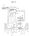
- Fig. 3 is a conceptual diagram for explaining the basic construction of a steering system for a motor vehicle in accordance with another embodiment of the present invention.
- the motor vehicle steering system according to this embodiment is different from the motor vehicle steering system shown in Fig. 1 in that the steering drive system for driving the steering mechanism 10 is not a dual system.
- components corresponding to those shown in Fig. 1 are denoted by the same reference characters as in Fig. 1.
- the motor vehicle steering system includes a steering mechanism 10 for causing a pair of steerable vehicle wheels (typically, front wheels) W, W to perform a steering operation, a steering wheel 30 to be brought into or out of mechanical engagement with the steering mechanism 10 via a clutch 20, and a counter-force actuator 40 for applying a reaction force to the steering wheel 30.
- a steering mechanism 10 for causing a pair of steerable vehicle wheels (typically, front wheels) W, W to perform a steering operation, a steering wheel 30 to be brought into or out of mechanical engagement with the steering mechanism 10 via a clutch 20, and a counter-force actuator 40 for applying a reaction force to the steering wheel 30.
- the steering mechanism 10 includes a steering shaft 11 extending transversely of a body of the motor vehicle, and knuckle arms 13, 13 respectively coupled to opposite ends of the steering shaft 11 via tie rods 12, 12 to support the steerable vehicle wheels W, W.
- the steering shaft 11 is supported in a housing 14 in an axially slidable manner, and a steering actuator 51 is incorporated in the midst of the steering shaft 11 in a coaxial relation.
- the steering actuator 51 comprises, for example, an electric motor having an output sufficient to drive the steering mechanism 10.
- a rack gear 11a is provided as a part of the steering shaft 11, and meshed with a pinion gear 22 provided at a distal end of a shaft 21 coupled to one side of the clutch 20.
- a shaft 23 coupled to the other side of the clutch 20 is coupled to the steering wheel 30. If the clutch 20 is in an engaged state, therefore, a steering torque applied to the steering wheel 30 is mechanically transmitted to the steering shaft 11 via the shaft 23, the clutch 20, the shaft 21, the pinion gear 22 and the rack gear 11a.
- the counter-force actuator 40 comprises an electric motor (e.g., three-phase brushless motor) which has a rotation shaft defined by the shaft 23 connecting the clutch 20 to the steering wheel 30 and a casing fixed to an appropriate portion of the vehicle body.
- the counter-force actuator 40 is provided with a torque sensor 41 for detecting a steering torque inputted from the steering wheel 30, and a steering angle sensor 42 for detecting an operation angle of the steering wheel 30.
- the clutch 20, the counter-force actuator 40 and the steering actuator 51 are controlled by a steering controlling section 60 which comprises a microprocessor and the like. More specifically, detection signals of the steering angle sensor 42 and a rotation angle sensor 52 are inputted to the steering controlling section 60.
- a steering position sensor 15 for detecting an axial position of the steering shaft 11 is provided in association with the steering shaft 11, and a detection signal of the steering position sensor 15 is also inputted to the steering controlling section 60. Further, a detection signal of a vehicle speed sensor 70 for detecting a vehicle speed is inputted to the steering controlling section 60.
- the vehicle speed sensor 70 may comprise, for example, a vehicle wheel speed sensor for detecting a rotation speed of each vehicle wheel.
- the steering controlling section 60 applies control signals to driver circuits 24, 43, 53 for driving the clutch 20, the counter-force actuator 40 and the steering actuator 51, respectively, on the basis of the signals inputted from the respective sensors.
- Fig. 4 is a flow chart for explaining a process to be performed by the steering controlling section 60.
- the steering controlling section 60 constantly checks if the steering actuator 51 operates normally (Step T1).
- the steering controlling section 60 sets the gear ratio of the degree of the rotation of the steering wheel 30 to the degree of the turning of the steerable vehicle wheels W, W according to the traveling state of the motor vehicle (VGR function).
- the steering controlling section 60 further sets a voltage command value for the steering actuator 51 on the basis of the gear ratio thus set and the degree of the operation of the steering wheel 30, and applies a control signal corresponding to the voltage command value to the driver circuit 53 (Step T2).
- a torque is outputted from the steering actuator 51 for sliding the steering shaft 11 in a direction corresponding to the direction of the operation of the steering wheel 30, whereby the steering operation is properly performed according to the traveling state of the motor vehicle and the operation of the steering wheel 30.
- the steering controlling section 60 deactuates the VGR function (Step T3), and establishes the engagement of the clutch 20 (Step T4).
- the engagement of the clutch 20 establishes the mechanical coupling between the steering mechanism 10 and the steering wheel 30 and, thereafter, the motor vehicle steering system functions as a power steering system employing the counter-force actuator 40 as a source of a steering assist force. That is, after the engagement of the clutch 20, the steering controlling section 60 generates a PWM control signal according to the operation angle of the steering wheel 30 (steering wheel angle), and inputs the PWM control signal to the driver circuit 43 of the counter-force actuator 40 so as to cause the counter-force actuator 40 to generate the steering assist force (Step T5).
- the steering assist force is properly generated by the counter-force actuator 40, whereby a steering assist operation can properly be performed according to the operation of the steering wheel 30.
- the engagement of the clutch 20 is established and the counter-force actuator 40 is PWM-controlled as the source of the steering assist force, if the steering actuator 51 malfunctions.
- the steering assist force is applied to the steering mechanism 10 from the counter-force actuator 40 according to the operation of the steering wheel 30. Therefore, the steering wheel 30 can easily be operated even after the engagement of the clutch 20, allowing for a practical fail-safe steering operation.
- the primary steering actuator 51M and the secondary steering actuator 51S are designed so as to have substantially the same maximum output and to be both controlled for driving thereof when the primary steering actuator 51M and the secondary steering actuator 51S operate normally.
- This arrangement is applied not only to the motor vehicle steering system according to the first embodiment but also to a motor vehicle steering system in which a steering drive system for driving the steering mechanism 10 is a dual drive system and no clutch 20 is provided.
- the motor vehicle steering system may be constructed so that, when the primary steering actuator 51M and the secondary steering actuator 51S operate normally, the driving force for driving the steering mechanism 10 is generated by both of the primary steering actuator 51M and the secondary steering actuator 51S and, when one of the primary steering actuator 51M and the secondary steering actuator 51S malfunctions, the driving force for driving the steering mechanism 10 is generated by the other normal steering actuator alone.
- the steering wheel 30 is employed as the operation member in the embodiments described above, a lever and the like may be employed as the operation member .
Abstract
Description
- The present invention relates to a motor vehicle steering system which is adapted to turn steerable vehicle wheels on the basis of the operation of an operation member such as a steering wheel.
- A steering system for a motor vehicle (so-called steer-by-wire system) has been proposed, which has no mechanical coupling between a steering wheel and a steering mechanism for turning steerable vehicle wheels, and is adapted to detect the direction and degree of the operation of the steering wheel and apply a driving force from a steering actuator such as an electric motor to the steering mechanism on the basis of the result of the detection.
- This arrangement makes it possible to flexibly change the ratio (gear ratio) of the degree of the rotation of the steering wheel to the degree of the turning of the steerable vehicle wheels depending on the traveling state of the vehicle for improvement of the maneuverability of the motor vehicle. The aforesaid arrangement advantageously prevents upward thrust of the steering wheel in the event of the collision of the motor vehicle, and allows for more flexible placement of the steering wheel.
- Since the steer-by-wire system has no mechanical coupling between the steering wheel and the steering mechanism, it is important to give a fail-safe consideration to a steering drive system. To this end, it is proposed to provide a clutch between the steering wheel and the steering mechanism for engagement and disengagement therebetween, whereby a mechanical coupling is established between the steering wheel and the steering mechanism with the clutch brought into engagement in the event of malfunction of the system.
- With the clutch interposed between the steering wheel and the steering mechanism, however, there is a possibility that the turning of the steerable vehicle wheels by the steering actuator undesirably causes passive rotation of the steering wheel when the drive control of the steering actuator is continued after the engagement of the clutch. Therefore, the driving of the steering actuator is stopped even if any component other than the steering actuator malfunctions. As a result, the steering wheel feels very heavy after the engagement of the clutch, so that a greater load is exerted on the clutch.
- It is an object of the present invention to provide a motor vehicle steering system which is capable of properly performing a steering operation even if a malfunction occurs.
- The motor vehicle steering system according to the present invention comprises: an operation member for steering a motor vehicle; a steering mechanism for turning steerable wheels of the motor vehicle; a first actuator and a second actuator each operative to apply a driving force to the steering mechanism; and a steering control section which, when the first and second actuators operate normally, causes at least one of the first and second actuators to apply the driving force to the steering mechanism and, when one of the first and second actuators malfunctions, causes the other normal actuator to apply the driving force to the steering mechanism.
- In accordance with a first aspect of the present invention, more specifically, there is provided a motor vehicle steering system, which comprises: an operation member for steering a motor vehicle; a steering mechanism for turning steerable wheels of the motor vehicle; a primary steering actuator and a secondary steering actuator coupled to the steering mechanism; a clutch mechanism operative to mechanically engage and disengage the operation member with respect to the steering mechanism; and a steering control section which, when the primary steering actuator and the secondary steering actuator operate normally, brings the clutch mechanism into a disengaged state to cause the primary steering actuator and the secondary steering actuator to generate a driving force for driving the steering mechanism and, when one of the primary steering actuator and the secondary steering actuator malfunctions, brings the clutch mechanism into an engaged state to cause the other normal steering actuator to generate a steering assist force according to operation of the operation member.
- According to this arrangement, when the primary steering actuator and the secondary steering actuator operate normally, the driving force is applied to the steering mechanism from both of the primary steering actuator and the secondary steering actuator. Even if the primary steering actuator and the secondary steering actuator each have a relatively small maximum output, the driving force can sufficiently be applied to the steering mechanism to properly perform a steering operation.
- If one of the primary steering actuator and the secondary steering actuator malfunctions, the clutch mechanism is brought into the engaged state, and the other normal steering actuator is controlled as a source of the steering assist force. Thus, the normal steering actuator applies the steering assist force to the steering mechanism according to the operation of the operation member. Therefore, the operation member can easily be operated even after the engagement of the clutch, allowing for a practical fail-safe steering operation.
- The motor vehicle steering system may further comprise a counter-force actuator for applying an operation reaction force to the operation member. In this case, the steering control section is preferably adapted to cause the counter-force actuator to generate an additional steering assist force according to the operation of the operation member when one of the primary steering actuator and the secondary steering actuator malfunctions.
- With this arrangement, the counter-force actuator is also controlled as the source of the steering assist force if the primary steering actuator or the secondary steering actuator malfunctions. Thus, a further greater steering assist force can be applied to the steering mechanism, so that the operation member can more easily be operated after the engagement of the clutch mechanism.
- Where the motor vehicle steering system further comprises the counter-force actuator for applying the operation reaction force to the operation member, the steering control section is adapted to bring the clutch mechanism into the engaged state to cause the primary steering actuator and the secondary steering actuator to generate the steering assist force according to the operation of the operation member when the counter-force actuator malfunctions.
- With this arrangement, the clutch mechanism is brought into the engaged state, and the primary steering actuator and the secondary steering actuator are controlled as the source of the steering assist force if the counter-force actuator malfunctions. Therefore, the operation member (e.g., steering wheel) can easily be operated, allowing for a practical fail-safe steering operation.
- In accordance with a second aspect of the present invention, there is provided a motor vehicle steering system, which comprises : an operation member for steering a motor vehicle; a steering mechanism for turning steerable wheels of the motor vehicle; a primary steering actuator and a secondary steering actuator coupled to the steering mechanism and having substantially the same maximum output; and steering control means which, when the primary steering actuator and the secondary steering actuator operate normally, causes the primary steering actuator and the secondary steering actuator to generate a driving force for driving the steering mechanism and, when one of the primary steering actuator and the secondary steering actuator malfunctions, causes the other normal steering actuator to generate the driving force for driving the steering mechanism.
- According to the present invention, when the primary steering actuator and the secondary steering actuator operate normally, the driving force is applied to the steering mechanism from both of the primary steering actuator and the secondary steering actuator. Therefore, the maximum outputs of the primary steering actuator and the secondary steering actuator can each be set at a smaller level.
- The primary steering actuator and the secondary steering actuator preferably each have a maximum output which is 60% to 70% of an output sufficient to drive the steering mechanism. In this case, the driving force can sufficiently be applied to the steering mechanism to properly perform the steering operation, when the primary steering actuator and the secondary steering actuator operate normally. Even if only one of the primary steering actuator and the secondary steering actuator operates normally, a driving force sufficient to maintain the direction of the steerable vehicle wheels can be applied to the steering mechanism.
- In accordance with a third aspect of the present invention, there is provided a motor vehicle steering system, which comprises: an operation member for steering a motor vehicle; a steering mechanism for turning steerable wheels of the motor vehicle; a steering actuator coupled to the steering mechanism; a clutch mechanism operative to mechanically engage and disengage the operation member with respect to the steering mechanism; a counter-force actuator for applying an operation reaction force to the operation member; and a steering control section which, when the steering actuator operates normally, brings the clutch mechanism into a disengaged state to cause the steering actuator to generate a driving force for driving the steering mechanism and, when the steering actuator malfunctions, brings the clutch mechanism into an engaged state to cause the counter-force actuator to generate a steering assist force according to operation of the operation member.
- According to the present invention, the clutch mechanism is brought into the engaged state and the counter-force actuator is controlled as a source of the steering assist force, if the steering actuator malfunctions. Thus, the counter-force actuator applies the steering assist force to the steering mechanism according to the operation of the operation member. Therefore, the operation member can easily be operated after the engagement of the clutch mechanism, allowing for a practical fail-safe steering operation.
- The foregoing and other objects, features and effects of the present invention will become more apparent from the following description of the preferred embodiments with reference to the attached drawings.
-
- Fig. 1 is a conceptual diagram for explaining the basic construction of a motor vehicle steering system according to one embodiment of the present invention;
- Fig. 2 is a flow chart for explaining a process to be performed by a steering controlling section provided in the motor vehicle steering system shown in Fig. 1;
- Fig. 3 is a conceptual diagram for explaining the basic construction of a motor vehicle steering system according to another embodiment of the present invention; and
- Fig. 4 is a flow chart for explaining a process to be performed by a steering controlling section provided in the motor vehicle steering system shown in Fig. 3.
-
- Fig. 1 is a conceptual diagram for explaining the basic construction of a steering system for a motor vehicle in accordance with one embodiment of the present invention. The motor vehicle steering system includes a
steering mechanism 10 for causing a pair of steer able vehicle wheels (typically, front wheels) W, W to perform a steering operation, asteering wheel 30 to be brought into or out of mechanical engagement with thesteering mechanism 10 via aclutch 20, and acounter-force actuator 40 for applying a reaction force to thesteering wheel 30. - The motor vehicle steering system has a dual steering drive system including a primary
steering drive system 50M and a secondarysteering drive system 50S for driving thesteering mechanism 10. The primarysteering drive system 50M includes aprimary steering actuator 51M, and a primaryrotation angle sensor 52M for detecting a rotation angle of theprimary steering actuator 51M. The secondarysteering drive system 50S includes asecondary steering actuator 51S, and a secondaryrotation angle sensor 52S for detecting a rotation angle of thesecondary steering actuator 51S. Theprimary steering actuator 51M and thesecondary steering actuator 51S each comprise an electric motor, for example, and have substantially the same maximum output which is equal to 60% to 70% of an output sufficient for theprimary steering actuator 51M or thesecondary steering actuator 51S alone to drive thesteering mechanism 10. - The
steering mechanism 10 includes asteering shaft 11 extending transversely of a body of the motor vehicle, andknuckle arms steering shaft 11 viatie rods steering shaft 11 is supported in ahousing 14 in an axially slidable manner, and theprimary steering actuator 51M is incorporated in the midst of thesteering shaft 11 in a coaxial relation. - A
rack gear 11a is provided as a part of thesteering shaft 11, and meshed with apinion gear 22 provided at a distal end of ashaft 21 coupled to one side of theclutch 20. Theshaft 21 is coupled to thesecondary steering actuator 51S, so that a driving force generated by thesecondary steering actuator 51S is inputted to theshaft 21. - With this arrangement, when the
primary steering actuator 51M is driven, a rotational motion of theprimary steering actuator 51M is converted into a sliding motion of thesteering shaft 11 by a motion converting mechanism comprising a ball thread and the like, so that the steerable vehicle wheels W, W are turned by the sliding motion of thesteering shaft 11. When thesecondary steering actuator 51S is driven, a rotational motion of theshaft 21 caused by thesecondary steering actuator 51S is converted into the sliding motion of thesteering shaft 11 by thepinion gear 22 and therack gear 11a, so that the steerable vehicle wheels W, W are turned by the sliding motion of thesteering shaft 11. - A
shaft 23 coupled to the other side of theclutch 20 is coupled to thesteering wheel 30. If theclutch 20 is in an engaged state, therefore, a steering torque applied to thesteering wheel 30 is mechanically transmitted to thesteering shaft 11 via theshaft 23, theclutch 20, theshaft 21, thepinion gear 22 and therack gear 11a. - The
counter-force actuator 40 comprises an electricmotor (e.g., three-phase brushless motor) which has a rotation shaft defined by theshaft 23 connecting theclutch 20 to thesteering wheel 30 and a casing fixed to an appropriate portion of the vehicle body. Thecounter-force actuator 40 is provided with atorque sensor 41 for detecting a steering torque inputted from thesteering wheel 30, and anoperation angle sensor 42 for detecting an operation angle of thesteering wheel 30. - The
clutch 20, thecounter-force actuator 40, theprimary steering actuator 51M and thesecondary steering actuator 51S are controlled by asteering controlling section 60 which comprises a microprocessor and the like. More specifically, detection signals of thesteering angle sensor 42, the primaryrotation angle sensor 52M and the secondaryrotation angle sensor 52S are inputted to thesteering controlling section 60. Asteering position sensor 15 for detecting an axial position of thesteering shaft 11 is provided in association with thesteering shaft 11, and a detection signal of thesteering position sensor 15 is also inputted to thesteering controlling section 60. Further, a detection signal of avehicle speed sensor 70 for detecting a vehicle speed is inputted to thesteering controlling section 60. Thevehicle speed sensor 70 may comprise, for example, a vehicle wheel speed sensor for detecting a rotation speed of each vehicle wheel. Thesteering controlling section 60 applies control signals todriver circuits counter-force actuator 40, theprimary steering actuator 51M and thesecondary steering actuator 51S, respectively, on the basis of the signals inputted from the respective sensors. - Fig. 2 is a flow chart for explaining a process to be performed by the
steering controlling section 60. Thesteering controlling section 60 constantly checks if theprimary steering actuator 51M, thesecondary steering actuator 51S and thecounter-force actuator 40 each operate normally, i.e., if any of theprimary steering actuator 51M, thesecondary steering actuator 51S and thecounter-force actuator 40 malfunctions (Step S1, S2). - If neither the
primary steering actuator 51M nor thesecondary steering actuator 51S malfunctions (NO in Step S1), and if thecounter-force actuator 40 does not malfunction (NO in Step S2), thesteering controlling section 60 controls theprimary steering actuator 51M and thesecondary steering actuator 51S for driving thereof (Step S3). In this embodiment, thesteering controlling section 60 has a VGR (variable gear ratio) function, and is adapted to set the ratio (gear ratio) of the degree of the rotation of thesteering wheel 30 to the degree of the turning of the steerable vehicle wheels W, W according to the traveling state of the motor vehicle. Thesteering controlling section 60 further sets voltage command values for theprimary steering actuator 51M and thesecondary steering actuator 51S on the basis of the gear ratio thus set and the degree of the operation of thesteering wheel 30, and apply control signals corresponding to the respective voltage command values to thedriver circuits primary steering actuator 51M and thesecondary steering actuator 51S for sliding the steeringshaft 11 in a direction corresponding to the direction of the operation of thesteering wheel 30, whereby the steering operation is properly performed according to the traveling state of the motor vehicle and the operation of thesteering wheel 30. - If one of the
primary steering actuator 51M and thesecondary steering actuator 51S malfunctions during the drive control thereof, thesteering controlling section 60 deactuates the VGR function (Step S4), and controls the other normal steering actuator to adjust the position of the steerable vehicle wheels W, W so that the rotation angle of thesteering wheel 30 and the steering angle of the steerable vehicle wheels W, W are brought into a proper relationship (i.e., a relationship where the neutral point of thesteering wheel 30 coincides with the neutral point of the steerable vehicle wheels W, W). After the positional adjustment of the steerable vehicle wheels W, W, the engagement of the clutch 20 is established (Step S5), and the driving of thecounter-force actuator 40 is stopped (Step S6). - The engagement of the clutch 20 establishes the mechanical coupling between the
steering mechanism 10 and thesteering wheel 30 and, thereafter, the motor vehicle steering system functions as a power steering system employing the normal steering actuator (theprimary steering actuator 51M or thesecondary steering actuator 51S) and thecounter-force actuator 40 as a source of a steering assist force . That is, after the engagement of the clutch 20, thesteering controlling section 60 generates a steering actuator PWM (pulse width modulation) control signal and a counter-force actuator PWM control signal according to the operation angle of the steering wheel 30 (steering wheel angle), and inputs these PWM control signals to the driver circuits of the normal steering actuator and thecounter-force actuator 40 so as to cause the normal steering actuator and thecounter-force actuator 40 to generate the steering assist force (Steps S7, S8). Thus, the steering assist force is properly generated by the normal steering actuator and thecounter-force actuator 40, whereby a steering assist operation can properly be performed according to the operation of thesteering wheel 30. - Ifthecounter-
force actuator 40 malfunctions, thesteering controlling section 60 first stops the driving of the counter-force actuator 40 (Step 39), and then deactuates the VGR function (Step S10). Thesteering controlling section 60 controls the normal steering actuator to adjust the position of the steerable vehicle wheels W, W so that the rotation angle of thesteering wheel 30 and the steering angle of the steerable vehicle wheels W, W are brought into the proper relationship, and then establishes the engagement of the clutch 20 (Step S11). - After the engagement of the clutch 20, the
steering mechanism 10 and thesteering wheel 30 are mechanically coupled to each other, so that the motor vehicle steering system functions as a power steering system employing theprimary steering actuator 51M and thesecondary steering actuator 51S as the source of the steering assist force. That is, after the engagement of the clutch 20, thesteering controlling section 60 generates a primary steering actuator PWM control signal and a secondary steering actuator PWM control signal according to the operation angle of the steering wheel 30 (steering wheel angle) , and inputs these PWM control signals to thedriver circuits primary steering actuator 51M and thesecondary steering actuator 51S so as to cause theprimary steering actuator 51M and thesecondary steering actuator 51S to generate the steering assist force (Step S12). Thus, the steering assist force is properly generated by theprimary steering actuator 51M and thesecondary steering actuator 51S, whereby the steering assist operation can properly be performed according to the operation of thesteering wheel 30. - In accordance with this embodiment, as described above, the
steering mechanism 10 is driven by both of theprimary steering system 50M and thesecondary steering system 50S when thecounter-force actuator 40, theprimary steering actuator 51M and thesecondary steering actuator 51S operate normally. Even if theprimary steering actuator 51M and thesecondary steering actuator 51S each have a relatively small maximum output, therefore, the driving force can sufficiently be applied to thesteering mechanism 10, so that the steering operation can properly be performed. - If one of the
primary steering actuator 51M and thesecondary steering actuator 51S malfunctions, the engagement of the clutch 20 is established, and the other normal steering actuator is PWM-controlled as the source of the steering assist force. Thus, the steering assist force is applied to thesteering mechanism 10 from the normal steering actuator according to the operation of thesteering wheel 30. Therefore, thesteering wheel 30 can easily be operated even after the engagement of the clutch 20, allowing for a practical fail-safe steering operation. - In this embodiment, the
counter-force actuator 40 is also PWM-controlled as the source of the steering assist force when theprimary steering actuator 51M or thesecondary steering actuator 51S malfunctions. This makes it possible to apply a further greater steering assist force to thesteering mechanism 10, so that thesteering wheel 30 can more easily be operated after the engagement of the clutch 20. - If the
counter-force actuator 40 malfunctions, the engagement of the clutch 20 is established, and theprimary steering actuator 51M and thesecondary steering actuator 51S are PWM-controlled as the source of the steering assist force. Therefore, thesteering wheel 30 can easily be operated, allowing for a practical fail-safe steering operation. - Fig. 3 is a conceptual diagram for explaining the basic construction of a steering system for a motor vehicle in accordance with another embodiment of the present invention. The motor vehicle steering system according to this embodiment is different from the motor vehicle steering system shown in Fig. 1 in that the steering drive system for driving the
steering mechanism 10 is not a dual system. In Fig. 3, components corresponding to those shown in Fig. 1 are denoted by the same reference characters as in Fig. 1. - The motor vehicle steering system includes a
steering mechanism 10 for causing a pair of steerable vehicle wheels (typically, front wheels) W, W to perform a steering operation, asteering wheel 30 to be brought into or out of mechanical engagement with thesteering mechanism 10 via a clutch 20, and acounter-force actuator 40 for applying a reaction force to thesteering wheel 30. - The
steering mechanism 10 includes a steeringshaft 11 extending transversely of a body of the motor vehicle, and knucklearms shaft 11 viatie rods shaft 11 is supported in ahousing 14 in an axially slidable manner, and asteering actuator 51 is incorporated in the midst of the steeringshaft 11 in a coaxial relation. The steeringactuator 51 comprises, for example, an electric motor having an output sufficient to drive thesteering mechanism 10. With this arrangement, when thesteering actuator 51 is driven, a rotational motion of thesteering actuator 51 is converted into a sliding motion of the steeringshaft 11 by a motion converting mechanism comprising a ball thread and the like, so that the steerable vehicle wheels W, W are turned by the sliding motion of the steeringshaft 11. - A
rack gear 11a is provided as a part of the steeringshaft 11, and meshed with apinion gear 22 provided at a distal end of ashaft 21 coupled to one side of the clutch 20. Ashaft 23 coupled to the other side of the clutch 20 is coupled to thesteering wheel 30. If the clutch 20 is in an engaged state, therefore, a steering torque applied to thesteering wheel 30 is mechanically transmitted to the steeringshaft 11 via theshaft 23, the clutch 20, theshaft 21, thepinion gear 22 and therack gear 11a. - The
counter-force actuator 40 comprises an electric motor (e.g., three-phase brushless motor) which has a rotation shaft defined by theshaft 23 connecting the clutch 20 to thesteering wheel 30 and a casing fixed to an appropriate portion of the vehicle body. Thecounter-force actuator 40 is provided with atorque sensor 41 for detecting a steering torque inputted from thesteering wheel 30, and asteering angle sensor 42 for detecting an operation angle of thesteering wheel 30. - The clutch 20, the
counter-force actuator 40 and thesteering actuator 51 are controlled by asteering controlling section 60 which comprises a microprocessor and the like. More specifically, detection signals of thesteering angle sensor 42 and arotation angle sensor 52 are inputted to thesteering controlling section 60. Asteering position sensor 15 for detecting an axial position of the steeringshaft 11 is provided in association with the steeringshaft 11, and a detection signal of thesteering position sensor 15 is also inputted to thesteering controlling section 60. Further, a detection signal of avehicle speed sensor 70 for detecting a vehicle speed is inputted to thesteering controlling section 60. Thevehicle speed sensor 70 may comprise, for example, a vehicle wheel speed sensor for detecting a rotation speed of each vehicle wheel. Thesteering controlling section 60 applies control signals todriver circuits counter-force actuator 40 and thesteering actuator 51, respectively, on the basis of the signals inputted from the respective sensors. - Fig. 4 is a flow chart for explaining a process to be performed by the
steering controlling section 60. Thesteering controlling section 60 constantly checks if thesteering actuator 51 operates normally (Step T1). - If the
steering actuator 51 does not malfunction, thesteering controlling section 60, for example, sets the gear ratio of the degree of the rotation of thesteering wheel 30 to the degree of the turning of the steerable vehicle wheels W, W according to the traveling state of the motor vehicle (VGR function). Thesteering controlling section 60 further sets a voltage command value for thesteering actuator 51 on the basis of the gear ratio thus set and the degree of the operation of thesteering wheel 30, and applies a control signal corresponding to the voltage command value to the driver circuit 53 (Step T2). Thus, a torque is outputted from the steeringactuator 51 for sliding the steeringshaft 11 in a direction corresponding to the direction of the operation of thesteering wheel 30, whereby the steering operation is properly performed according to the traveling state of the motor vehicle and the operation of thesteering wheel 30. - If the
steering actuator 51 malfunctions during the drive control thereof, thesteering controlling section 60 deactuates the VGR function (Step T3), and establishes the engagement of the clutch 20 (Step T4). - The engagement of the clutch 20 establishes the mechanical coupling between the
steering mechanism 10 and thesteering wheel 30 and, thereafter, the motor vehicle steering system functions as a power steering system employing thecounter-force actuator 40 as a source of a steering assist force. That is, after the engagement of the clutch 20, thesteering controlling section 60 generates a PWM control signal according to the operation angle of the steering wheel 30 (steering wheel angle), and inputs the PWM control signal to thedriver circuit 43 of thecounter-force actuator 40 so as to cause thecounter-force actuator 40 to generate the steering assist force (Step T5). Thus, the steering assist force is properly generated by thecounter-force actuator 40, whereby a steering assist operation can properly be performed according to the operation of thesteering wheel 30. - In accordance with this embodiment, the engagement of the clutch 20 is established and the
counter-force actuator 40 is PWM-controlled as the source of the steering assist force, if thesteering actuator 51 malfunctions. Thus, the steering assist force is applied to thesteering mechanism 10 from thecounter-force actuator 40 according to the operation of thesteering wheel 30. Therefore, thesteering wheel 30 can easily be operated even after the engagement of the clutch 20, allowing for a practical fail-safe steering operation. - While the two specific embodiments of the present invention have thus been described, the invention may be embodied in any other ways. In accordance with the invention, the
primary steering actuator 51M and thesecondary steering actuator 51S are designed so as to have substantially the same maximum output and to be both controlled for driving thereof when theprimary steering actuator 51M and thesecondary steering actuator 51S operate normally. This arrangement is applied not only to the motor vehicle steering system according to the first embodiment but also to a motor vehicle steering system in which a steering drive system for driving thesteering mechanism 10 is a dual drive system and no clutch 20 is provided. In this case, the motor vehicle steering system may be constructed so that, when theprimary steering actuator 51M and thesecondary steering actuator 51S operate normally, the driving force for driving thesteering mechanism 10 is generated by both of theprimary steering actuator 51M and thesecondary steering actuator 51S and, when one of theprimary steering actuator 51M and thesecondary steering actuator 51S malfunctions, the driving force for driving thesteering mechanism 10 is generated by the other normal steering actuator alone. - Although the
steering wheel 30 is employed as the operation member in the embodiments described above, a lever and the like may be employed as the operation member . - While the present invention has been described in detail by way of the embodiments thereof, it should be understood that the foregoing disclosure is merely illustrative of the technical principles of the present invention but not limitative of the same. The spirit and scope of the present invention are to be limited only by the appended claims.
- This application corresponds to Japanese Patent Application No. 2000-347081 filed to the Japanese Patent Office on November 14, 2000, the disclosure thereof being incorporated herein by reference.
Claims (5)
- A motor vehicle steering system comprising:characterized byan operation member (30) for steering a motor vehicle;a steering mechanism (10) for turning steerable wheels (W) of the motor vehicle;a first actuator (51M; 51) and a second actuator (51S; 40) each operative to apply a driving force to the steering mechanism (10); anda clutch mechanism (20) operative to mechanically engage and disengage the operation member (30) with respect to the steering mechanism (10);
a steering control section (60) which, when the first and second actuators (51M, 51S; 51S, 40) operate normally, brings the clutch mechanism (20) into a disengaged state and causes the first and second actuators (51M, 51S; 51S, 40) to generate the driving force for driving the steering mechanism (10) and, when one of the first and second actuators (51M, 51S; 51S, 40) malfunctions, brings the clutch mechanism (20) into an engaged state and causes the other normal actuator to generate a steering assist force according to operation of the operation member (30). - The steering system of claim 1, characterized in thatthe first actuator is a primary steering actuator (51M) coupled to the steering mechanism (10); andthe second actuator is a secondary steering actuator (51S) coupled to the steering mechanism (10).
- The steering system of claim 2, characterized by a counter-force actuator (40) for applying an operation reaction force to the operation member (30),
wherein, when one of the primary steering actuator (51M) and the secondary steering actuator (51S) malfunctions, the steering control section (60) causes the counter-force actuator (40) to generate an additional steering assist force according to the operation of the operation member (30). - The steering system of claim 2 or 3, characterized by a counter-force actuator (40) for applying an operation reaction force to the operation member (30),
wherein, when the counter-force actuator (40) malfunctions, the steering control section (60) brings the clutch mechanism (20) into the engaged state to cause at least one of the primary steering actuator (51M) and the secondary steering actuator (51S) to generate the steering assist force according to the operation of the operation member (30). - The steering system of claim 1, characterized in thatwherein, when the steering actuator (51) operates normally, the steering control section (60) brings the clutch mechanism (20) into a disengaged state and causes the steering actuator (51) to generate the driving force for driving the steering mechanism (10) and, when the steering actuator (51) malfunctions, brings the clutch mechanism (20) into an engaged state and causes the counter-force actuator (40) to generate a steering assist force according to operation of the operation member (30).the first actuator is a steering actuator (51) coupled to the steering mechanism (10);the second actuator is a counter-force actuator (40) for applying an operation reaction force to the operation member (30); and
Applications Claiming Priority (2)
| Application Number | Priority Date | Filing Date | Title |
|---|---|---|---|
| JP2000347081A JP4419114B2 (en) | 2000-11-14 | 2000-11-14 | Vehicle steering system |
| JP2000347081 | 2000-11-14 |
Publications (3)
| Publication Number | Publication Date |
|---|---|
| EP1205371A2 true EP1205371A2 (en) | 2002-05-15 |
| EP1205371A3 EP1205371A3 (en) | 2003-07-02 |
| EP1205371B1 EP1205371B1 (en) | 2006-08-02 |
Family
ID=18820866
Family Applications (1)
| Application Number | Title | Priority Date | Filing Date |
|---|---|---|---|
| EP01126850A Expired - Lifetime EP1205371B1 (en) | 2000-11-14 | 2001-11-12 | Motor vehicle steering system |
Country Status (4)
| Country | Link |
|---|---|
| US (1) | US6442462B1 (en) |
| EP (1) | EP1205371B1 (en) |
| JP (1) | JP4419114B2 (en) |
| DE (2) | DE60121898D1 (en) |
Cited By (11)
| Publication number | Priority date | Publication date | Assignee | Title |
|---|---|---|---|---|
| FR2837772A1 (en) * | 2002-03-27 | 2003-10-03 | Koyo Seiko Co | STEERING SYSTEM FOR A MOTOR VEHICLE. |
| EP1384648A2 (en) * | 2002-07-26 | 2004-01-28 | Toyoda Koki Kabushiki Kaisha | Vehicle steering control system |
| GB2392145A (en) * | 2002-08-20 | 2004-02-25 | Visteon Global Tech Inc | Plural mode steering system |
| EP1384650A3 (en) * | 2002-07-26 | 2004-09-29 | Toyoda Koki Kabushiki Kaisha | Vehicle steering control system |
| EP1481874A2 (en) * | 2003-05-29 | 2004-12-01 | Nissan Motor Company, Limited | Steering apparatus and method for automotive vehicle |
| EP1795430A2 (en) | 2005-12-09 | 2007-06-13 | Nissan Motor Co., Ltd. | Vehicle steering control |
| FR2928605A3 (en) * | 2008-03-12 | 2009-09-18 | Renault Sas | Steering system for steering wheel of motor vehicle, has generation unit generating effort moving in displacement direction of fly-wheel when system is in mechanical coupling configuration between fly-wheel and steering wheels |
| US7708108B2 (en) * | 2006-03-01 | 2010-05-04 | Nissan Motor Co., Ltd. | Vehicle steering control apparatus and method |
| CN104718123A (en) * | 2012-10-03 | 2015-06-17 | 日产自动车株式会社 | Steering control device, and steering control method |
| EP3098139A1 (en) * | 2015-05-29 | 2016-11-30 | Jtekt Corporation | Steering apparatus |
| US20180201298A1 (en) * | 2017-01-18 | 2018-07-19 | Jtekt Corporation | Steer-by-wire steering system |
Families Citing this family (57)
| Publication number | Priority date | Publication date | Assignee | Title |
|---|---|---|---|---|
| DE10057242A1 (en) * | 2000-11-18 | 2002-05-29 | Bosch Gmbh Robert | Coupling for a steer-by-wire steering system |
| US6535805B2 (en) * | 2001-08-10 | 2003-03-18 | Delphi Technologies, Inc. | Robust determination of hand-wheel position |
| US6655709B2 (en) * | 2002-01-29 | 2003-12-02 | Trw Inc. | Steer-by-wire steering apparatus with actuatable mechanism |
| US6659218B2 (en) * | 2002-03-18 | 2003-12-09 | Delphi Technologies, Inc. | Steering system |
| US20030230448A1 (en) * | 2002-06-18 | 2003-12-18 | Bayerische Motoren Werke Ag | Vehicle steering system, steer feel control system and method for providing steer feel |
| US6580989B1 (en) | 2002-08-20 | 2003-06-17 | Visteon Global Technologies, Inc. | Motor vehicle steering system |
| US6694239B1 (en) * | 2002-12-17 | 2004-02-17 | Visteon Global Technologies, Inc. | System and method of controlling vehicle steer-by-wire systems |
| US6776252B1 (en) | 2003-01-24 | 2004-08-17 | Visteon Global Technologies, Inc. | Steer-by-wire system and method for actuating road wheels of a vehicle |
| US6966398B2 (en) * | 2003-03-26 | 2005-11-22 | Trw Automotive U.S. Llc | Apparatus for controlling a power-assisted steering gear in response to vehicle speed |
| JP2004351975A (en) * | 2003-05-27 | 2004-12-16 | Ntn Corp | Fail-safe mechanism of steer-by-wire system and steer-by-wire system |
| DE602004025068D1 (en) * | 2003-06-11 | 2010-03-04 | Nissan Motor | Fail-safe steering system for a motor vehicle |
| US6976555B2 (en) * | 2003-06-30 | 2005-12-20 | Visteon Global Technologies, Inc. | Motor vehicle steering system |
| US7004279B2 (en) | 2003-08-28 | 2006-02-28 | Nissan Motor Co., Ltd. | Vehicle steering system |
| CN100436227C (en) | 2003-10-02 | 2008-11-26 | 日产自动车株式会社 | Vehicle steering apparatus |
| JP4449397B2 (en) * | 2003-10-02 | 2010-04-14 | 日産自動車株式会社 | Vehicle steering system |
| US7174987B2 (en) * | 2003-10-16 | 2007-02-13 | Visteon Global Technologies, Inc. | End of travel feature for steer by wire vehicle |
| US6899196B2 (en) * | 2003-10-16 | 2005-05-31 | Visteon Global Technologies, Inc. | Driver interface system for steer-by-wire system |
| US6926112B2 (en) * | 2003-10-16 | 2005-08-09 | Visteon Global Technologies, Inc. | End of travel system and method for steer by wire systems |
| DE10352495A1 (en) * | 2003-11-11 | 2005-06-09 | Robert Bosch Gmbh | Method for driving a coupling unit |
| US7726692B2 (en) * | 2003-12-01 | 2010-06-01 | Honda Motor Co., Ltd. | Steering handle and steering system |
| SE526240C2 (en) * | 2003-12-17 | 2005-08-02 | Volvo Bussar Ab | Method and computer product of a control system of a vehicle |
| US20050155809A1 (en) * | 2004-01-20 | 2005-07-21 | Krzesicki Richard M. | Mechanical clutch coupling back-up for electric steering system |
| US6929086B1 (en) | 2004-02-18 | 2005-08-16 | Visteon Global Technologies, Inc. | Motor vehicle steering system |
| JP4347100B2 (en) * | 2004-03-17 | 2009-10-21 | Ntn株式会社 | Steer-by-wire system |
| US20050274565A1 (en) * | 2004-06-09 | 2005-12-15 | Greenwell Randall G | Steer by wire motor control algorithm |
| JP4222282B2 (en) * | 2004-10-01 | 2009-02-12 | トヨタ自動車株式会社 | Vehicle steering device |
| US7500537B2 (en) | 2004-08-25 | 2009-03-10 | Toyota Jidosha Kabushiki Kaisha | Steering apparatus for vehicle |
| JP4682639B2 (en) * | 2005-02-15 | 2011-05-11 | 日産自動車株式会社 | Steering control device |
| US7664584B2 (en) * | 2005-03-01 | 2010-02-16 | Nissan Motor Co., Ltd. | Steering control system |
| JP4506509B2 (en) * | 2005-03-01 | 2010-07-21 | 日産自動車株式会社 | Steering control device |
| JP4725132B2 (en) * | 2005-03-01 | 2011-07-13 | 日産自動車株式会社 | Steering control device |
| JP2006321271A (en) | 2005-05-17 | 2006-11-30 | Jtekt Corp | Steering gear for vehicle |
| JP2007022461A (en) * | 2005-07-20 | 2007-02-01 | Fuji Kiko Co Ltd | Steering gear for vehicle |
| JP4956775B2 (en) * | 2005-08-25 | 2012-06-20 | 日産自動車株式会社 | Steering control device |
| JP4984504B2 (en) * | 2005-11-29 | 2012-07-25 | 日産自動車株式会社 | Vehicle steering control device |
| JP4622851B2 (en) * | 2005-12-27 | 2011-02-02 | トヨタ自動車株式会社 | Vehicle steering device |
| US10378896B2 (en) * | 2006-02-27 | 2019-08-13 | Trimble Inc. | Method and system for planning the path of an agricultural vehicle |
| JP4525621B2 (en) * | 2006-03-14 | 2010-08-18 | トヨタ自動車株式会社 | Vehicle steering device |
| US7810605B2 (en) * | 2006-12-28 | 2010-10-12 | Nissan Motor Co., Ltd. | Vehicle steering device and control method for vehicle steering device |
| JP5239245B2 (en) * | 2007-07-27 | 2013-07-17 | 日産自動車株式会社 | Vehicle steering control device |
| US7798279B2 (en) * | 2007-10-18 | 2010-09-21 | Trw Automotive U.S. Llc | Steer-by-wire steering apparatus with actuatable mechanism |
| KR101349467B1 (en) | 2008-05-27 | 2014-01-09 | 현대자동차주식회사 | Failsafe Method for Steer By Wire Vehicle |
| US8234045B2 (en) * | 2008-09-24 | 2012-07-31 | Robert Bosch Gmbh | Failure mode effects mitigation in drive-by-wire systems |
| JP5321043B2 (en) * | 2008-12-25 | 2013-10-23 | 日産自動車株式会社 | Vehicle steering control device and vehicle steering control method |
| WO2014057516A1 (en) * | 2012-10-10 | 2014-04-17 | トヨタ自動車株式会社 | Steering system |
| US9266552B2 (en) | 2013-08-05 | 2016-02-23 | Rene Guerster | Steering system for wheeled land vehicle |
| DE102013217136B4 (en) | 2013-08-28 | 2022-11-10 | Volkswagen Aktiengesellschaft | Method for reducing an impact of a steering assist malfunction |
| DE112015001303T5 (en) * | 2014-03-19 | 2017-01-05 | Hitachi Automotive Systems, Ltd. | Power steering device and control device for a power steering device |
| KR101970979B1 (en) * | 2014-04-16 | 2019-04-23 | 주식회사 만도 | Safety apparatus for Steer-By-Wire |
| KR101639479B1 (en) * | 2014-10-13 | 2016-07-13 | 주식회사 만도 | Methods and Apparatus for controlling Electic power steering |
| CN107454881A (en) * | 2015-04-14 | 2017-12-08 | 沃尔沃卡车集团 | method for optimizing steering assistance |
| MX369190B (en) * | 2015-06-03 | 2019-10-31 | Nissan Motor | Vehicle control device and vehicle control method. |
| JP2017001562A (en) * | 2015-06-11 | 2017-01-05 | Kyb株式会社 | Steering control device |
| US10029642B2 (en) * | 2016-03-18 | 2018-07-24 | Hyundai America Technical Center, Inc | Enhanced steering system utilizing fixed dab for occupant protection in frontal impacts with laterial loading |
| US10358162B2 (en) * | 2016-10-03 | 2019-07-23 | Jtekt Corporation | Steering control device |
| DE102018211764A1 (en) * | 2018-07-16 | 2020-01-16 | Robert Bosch Gmbh | Method for determining and / or monitoring a mechanical condition of a tie rod assembly |
| JP7200210B2 (en) * | 2020-12-25 | 2023-01-06 | 本田技研工業株式会社 | moving body |
Family Cites Families (5)
| Publication number | Priority date | Publication date | Assignee | Title |
|---|---|---|---|---|
| JPS63232074A (en) * | 1987-03-20 | 1988-09-28 | Toyota Central Res & Dev Lab Inc | Steering device for vehicle |
| JPH0796388B2 (en) * | 1987-04-13 | 1995-10-18 | 株式会社日立製作所 | Electric power steering device |
| DE4304664C2 (en) * | 1993-02-16 | 2000-04-06 | Daimler Chrysler Ag | Control device, in particular steering for motor vehicles |
| DE19947265A1 (en) * | 1999-01-22 | 2000-07-27 | Mercedes Benz Lenkungen Gmbh | Error-tolerant motor vehicle steering system with autonomous servo steering has mechanical clutch between steering wheel and wheel angle adjusting drive to ensure servo motor operation if one motor fails |
| JP2001301639A (en) * | 2000-04-24 | 2001-10-31 | Nissan Motor Co Ltd | Steering device for vehicle |
-
2000
- 2000-11-14 JP JP2000347081A patent/JP4419114B2/en not_active Expired - Fee Related
-
2001
- 2001-11-01 US US09/985,063 patent/US6442462B1/en not_active Expired - Lifetime
- 2001-11-12 DE DE60121898A patent/DE60121898D1/en not_active Expired - Lifetime
- 2001-11-12 DE DE60121898T patent/DE60121898T8/en active Active
- 2001-11-12 EP EP01126850A patent/EP1205371B1/en not_active Expired - Lifetime
Non-Patent Citations (1)
| Title |
|---|
| None |
Cited By (25)
| Publication number | Priority date | Publication date | Assignee | Title |
|---|---|---|---|---|
| FR2837772A1 (en) * | 2002-03-27 | 2003-10-03 | Koyo Seiko Co | STEERING SYSTEM FOR A MOTOR VEHICLE. |
| EP1384648A2 (en) * | 2002-07-26 | 2004-01-28 | Toyoda Koki Kabushiki Kaisha | Vehicle steering control system |
| EP1384650A3 (en) * | 2002-07-26 | 2004-09-29 | Toyoda Koki Kabushiki Kaisha | Vehicle steering control system |
| EP1384648A3 (en) * | 2002-07-26 | 2010-06-02 | Jtekt Corporation | Vehicle steering control system |
| US6915194B2 (en) | 2002-07-26 | 2005-07-05 | Toyoda Koki Kabushiki Kaisha | Vehicle steering control system |
| DE10335949B4 (en) * | 2002-08-20 | 2011-03-10 | Visteon Global Technologies Inc., Van Buren | Method for controlling a steering of a vehicle |
| GB2392145A (en) * | 2002-08-20 | 2004-02-25 | Visteon Global Tech Inc | Plural mode steering system |
| GB2392145B (en) * | 2002-08-20 | 2004-12-15 | Visteon Global Tech Inc | Motor vehicle steering system |
| EP1481874A3 (en) * | 2003-05-29 | 2005-04-06 | Nissan Motor Company, Limited | Steering apparatus and method for automotive vehicle |
| US6938721B2 (en) | 2003-05-29 | 2005-09-06 | Nissan Motor Co., Ltd. | Steering apparatus and method for automotive vehicle |
| EP1481874A2 (en) * | 2003-05-29 | 2004-12-01 | Nissan Motor Company, Limited | Steering apparatus and method for automotive vehicle |
| EP1795430A2 (en) | 2005-12-09 | 2007-06-13 | Nissan Motor Co., Ltd. | Vehicle steering control |
| EP1795430A3 (en) * | 2005-12-09 | 2008-06-04 | Nissan Motor Co., Ltd. | Vehicle steering control |
| US7900742B2 (en) * | 2005-12-09 | 2011-03-08 | Nissan Motor Co., Ltd. | Vehicle steering control |
| US7708108B2 (en) * | 2006-03-01 | 2010-05-04 | Nissan Motor Co., Ltd. | Vehicle steering control apparatus and method |
| FR2928605A3 (en) * | 2008-03-12 | 2009-09-18 | Renault Sas | Steering system for steering wheel of motor vehicle, has generation unit generating effort moving in displacement direction of fly-wheel when system is in mechanical coupling configuration between fly-wheel and steering wheels |
| CN104718123A (en) * | 2012-10-03 | 2015-06-17 | 日产自动车株式会社 | Steering control device, and steering control method |
| EP2905201A4 (en) * | 2012-10-03 | 2015-11-04 | Nissan Motor | Steering control device, and steering control method |
| RU2630569C2 (en) * | 2012-10-03 | 2017-09-11 | Ниссан Мотор Ко., Лтд. | Vehicle steering control device and steering control method |
| EP3098139A1 (en) * | 2015-05-29 | 2016-11-30 | Jtekt Corporation | Steering apparatus |
| CN106184349A (en) * | 2015-05-29 | 2016-12-07 | 株式会社捷太格特 | Steering apparatus |
| US9988072B2 (en) | 2015-05-29 | 2018-06-05 | Jtekt Corporation | Steering apparatus |
| US20180201298A1 (en) * | 2017-01-18 | 2018-07-19 | Jtekt Corporation | Steer-by-wire steering system |
| EP3351455A1 (en) * | 2017-01-18 | 2018-07-25 | JTEKT Corporation | Steer-by-wire steering system |
| US10850763B2 (en) | 2017-01-18 | 2020-12-01 | Jtekt Corporation | Steer-by-wire steering system |
Also Published As
| Publication number | Publication date |
|---|---|
| JP2002145098A (en) | 2002-05-22 |
| DE60121898T2 (en) | 2007-02-08 |
| JP4419114B2 (en) | 2010-02-24 |
| DE60121898T8 (en) | 2007-12-13 |
| US20020059021A1 (en) | 2002-05-16 |
| EP1205371B1 (en) | 2006-08-02 |
| US6442462B1 (en) | 2002-08-27 |
| EP1205371A3 (en) | 2003-07-02 |
| DE60121898D1 (en) | 2006-09-14 |
Similar Documents
| Publication | Publication Date | Title |
|---|---|---|
| US6442462B1 (en) | Motor vehicle steering system | |
| US7664584B2 (en) | Steering control system | |
| EP0857638B1 (en) | Steering apparatus for automobile | |
| EP1607303B1 (en) | Vehicle steering apparatus | |
| EP1925532B1 (en) | Steering system for vehicle | |
| KR102344546B1 (en) | Apparatus for controlling handle of vehicls | |
| JP2004352111A (en) | Vehicular steering device | |
| US20210046972A1 (en) | Steering device | |
| US20030201136A1 (en) | Vehicle steering apparatus | |
| JP2001026277A (en) | Steering device for vehicle | |
| KR100916174B1 (en) | Steering device | |
| EP1445171A2 (en) | Automotive steering system | |
| JP2018020743A (en) | Vehicular steering device | |
| JP4178217B2 (en) | Vehicle steering system | |
| JP4107030B2 (en) | Electric power steering device | |
| JP3648440B2 (en) | Vehicle steering system | |
| JP2004224077A (en) | Electric power steering device | |
| JP2017001611A (en) | Steering control device | |
| JP3897971B2 (en) | Vehicle steering system | |
| JP3876143B2 (en) | Vehicle steering system | |
| JP3991643B2 (en) | Vehicle steering system | |
| JP3837317B2 (en) | Vehicle steering system | |
| JP2017226319A (en) | Vehicular steering device | |
| JP2007269219A (en) | Vehicular steering device | |
| JP4594129B2 (en) | Vehicle steering device |
Legal Events
| Date | Code | Title | Description |
|---|---|---|---|
| PUAI | Public reference made under article 153(3) epc to a published international application that has entered the european phase |
Free format text: ORIGINAL CODE: 0009012 |
|
| AK | Designated contracting states |
Kind code of ref document: A2 Designated state(s): AT BE CH CY DE DK ES FI FR GB GR IE IT LI LU MC NL PT SE TR |
|
| AX | Request for extension of the european patent |
Free format text: AL;LT;LV;MK;RO;SI |
|
| PUAL | Search report despatched |
Free format text: ORIGINAL CODE: 0009013 |
|
| AK | Designated contracting states |
Designated state(s): AT BE CH CY DE DK ES FI FR GB GR IE IT LI LU MC NL PT SE TR |
|
| AX | Request for extension of the european patent |
Extension state: AL LT LV MK RO SI |
|
| 17P | Request for examination filed |
Effective date: 20031220 |
|
| AKX | Designation fees paid |
Designated state(s): DE FR GB |
|
| 17Q | First examination report despatched |
Effective date: 20040317 |
|
| GRAP | Despatch of communication of intention to grant a patent |
Free format text: ORIGINAL CODE: EPIDOSNIGR1 |
|
| RIC1 | Information provided on ipc code assigned before grant |
Ipc: B62D 5/04 20060101AFI20060215BHEP Ipc: B62D 137/00 20060101ALN20060215BHEP Ipc: B62D 113/00 20060101ALN20060215BHEP Ipc: B62D 101/00 20060101ALN20060215BHEP Ipc: B62D 119/00 20060101ALN20060215BHEP Ipc: B62D 6/00 20060101ALI20060215BHEP |
|
| RAP1 | Party data changed (applicant data changed or rights of an application transferred) |
Owner name: JTEKT CORPORATION |
|
| GRAS | Grant fee paid |
Free format text: ORIGINAL CODE: EPIDOSNIGR3 |
|
| GRAA | (expected) grant |
Free format text: ORIGINAL CODE: 0009210 |
|
| AK | Designated contracting states |
Kind code of ref document: B1 Designated state(s): DE FR GB |
|
| REG | Reference to a national code |
Ref country code: GB Ref legal event code: FG4D |
|
| REF | Corresponds to: |
Ref document number: 60121898 Country of ref document: DE Date of ref document: 20060914 Kind code of ref document: P |
|
| ET | Fr: translation filed | ||
| PLBE | No opposition filed within time limit |
Free format text: ORIGINAL CODE: 0009261 |
|
| STAA | Information on the status of an ep patent application or granted ep patent |
Free format text: STATUS: NO OPPOSITION FILED WITHIN TIME LIMIT |
|
| 26N | No opposition filed |
Effective date: 20070503 |
|
| PGFP | Annual fee paid to national office [announced via postgrant information from national office to epo] |
Ref country code: GB Payment date: 20071107 Year of fee payment: 7 |
|
| GBPC | Gb: european patent ceased through non-payment of renewal fee |
Effective date: 20081112 |
|
| PG25 | Lapsed in a contracting state [announced via postgrant information from national office to epo] |
Ref country code: GB Free format text: LAPSE BECAUSE OF NON-PAYMENT OF DUE FEES Effective date: 20081112 |
|
| REG | Reference to a national code |
Ref country code: FR Ref legal event code: PLFP Year of fee payment: 15 |
|
| REG | Reference to a national code |
Ref country code: FR Ref legal event code: PLFP Year of fee payment: 16 |
|
| REG | Reference to a national code |
Ref country code: FR Ref legal event code: PLFP Year of fee payment: 17 |
|
| PGFP | Annual fee paid to national office [announced via postgrant information from national office to epo] |
Ref country code: FR Payment date: 20171012 Year of fee payment: 17 Ref country code: DE Payment date: 20171108 Year of fee payment: 17 |
|
| REG | Reference to a national code |
Ref country code: DE Ref legal event code: R119 Ref document number: 60121898 Country of ref document: DE |
|
| PG25 | Lapsed in a contracting state [announced via postgrant information from national office to epo] |
Ref country code: DE Free format text: LAPSE BECAUSE OF NON-PAYMENT OF DUE FEES Effective date: 20190601 Ref country code: FR Free format text: LAPSE BECAUSE OF NON-PAYMENT OF DUE FEES Effective date: 20181130 |