EP1205260A2 - Torpedosonar mit mehreren Wandlern - Google Patents
Torpedosonar mit mehreren Wandlern Download PDFInfo
- Publication number
- EP1205260A2 EP1205260A2 EP01126181A EP01126181A EP1205260A2 EP 1205260 A2 EP1205260 A2 EP 1205260A2 EP 01126181 A EP01126181 A EP 01126181A EP 01126181 A EP01126181 A EP 01126181A EP 1205260 A2 EP1205260 A2 EP 1205260A2
- Authority
- EP
- European Patent Office
- Prior art keywords
- zone
- torpedo
- zones
- sonar
- transducers
- Prior art date
- Legal status (The legal status is an assumption and is not a legal conclusion. Google has not performed a legal analysis and makes no representation as to the accuracy of the status listed.)
- Granted
Links
- 230000007704 transition Effects 0.000 claims description 6
- 238000010586 diagram Methods 0.000 description 5
- XLYOFNOQVPJJNP-UHFFFAOYSA-N water Substances O XLYOFNOQVPJJNP-UHFFFAOYSA-N 0.000 description 4
- 230000005540 biological transmission Effects 0.000 description 2
- 238000001514 detection method Methods 0.000 description 2
- 238000011161 development Methods 0.000 description 2
- 230000018109 developmental process Effects 0.000 description 2
- 241000251729 Elasmobranchii Species 0.000 description 1
- 230000000712 assembly Effects 0.000 description 1
- 238000000429 assembly Methods 0.000 description 1
- 230000015572 biosynthetic process Effects 0.000 description 1
- 230000004807 localization Effects 0.000 description 1
- 230000035945 sensitivity Effects 0.000 description 1
- 238000002604 ultrasonography Methods 0.000 description 1
Images

Classifications
-
- F—MECHANICAL ENGINEERING; LIGHTING; HEATING; WEAPONS; BLASTING
- F42—AMMUNITION; BLASTING
- F42B—EXPLOSIVE CHARGES, e.g. FOR BLASTING, FIREWORKS, AMMUNITION
- F42B19/00—Marine torpedoes, e.g. launched by surface vessels or submarines; Sea mines having self-propulsion means
- F42B19/005—Nose caps for torpedoes; Coupling torpedo-case parts together
-
- G—PHYSICS
- G10—MUSICAL INSTRUMENTS; ACOUSTICS
- G10K—SOUND-PRODUCING DEVICES; METHODS OR DEVICES FOR PROTECTING AGAINST, OR FOR DAMPING, NOISE OR OTHER ACOUSTIC WAVES IN GENERAL; ACOUSTICS NOT OTHERWISE PROVIDED FOR
- G10K11/00—Methods or devices for transmitting, conducting or directing sound in general; Methods or devices for protecting against, or for damping, noise or other acoustic waves in general
- G10K11/18—Methods or devices for transmitting, conducting or directing sound
- G10K11/26—Sound-focusing or directing, e.g. scanning
- G10K11/32—Sound-focusing or directing, e.g. scanning characterised by the shape of the source
-
- G—PHYSICS
- G10—MUSICAL INSTRUMENTS; ACOUSTICS
- G10K—SOUND-PRODUCING DEVICES; METHODS OR DEVICES FOR PROTECTING AGAINST, OR FOR DAMPING, NOISE OR OTHER ACOUSTIC WAVES IN GENERAL; ACOUSTICS NOT OTHERWISE PROVIDED FOR
- G10K11/00—Methods or devices for transmitting, conducting or directing sound in general; Methods or devices for protecting against, or for damping, noise or other acoustic waves in general
- G10K11/18—Methods or devices for transmitting, conducting or directing sound
- G10K11/26—Sound-focusing or directing, e.g. scanning
- G10K11/34—Sound-focusing or directing, e.g. scanning using electrical steering of transducer arrays, e.g. beam steering
-
- H—ELECTRICITY
- H01—ELECTRIC ELEMENTS
- H01Q—ANTENNAS, i.e. RADIO AERIALS
- H01Q1/00—Details of, or arrangements associated with, antennas
- H01Q1/27—Adaptation for use in or on movable bodies
- H01Q1/28—Adaptation for use in or on aircraft, missiles, satellites, or balloons
- H01Q1/281—Nose antennas
-
- H—ELECTRICITY
- H01—ELECTRIC ELEMENTS
- H01Q—ANTENNAS, i.e. RADIO AERIALS
- H01Q21/00—Antenna arrays or systems
- H01Q21/06—Arrays of individually energised antenna units similarly polarised and spaced apart
Definitions
- the invention relates to a torpedo sonar with a plurality of electroacoustic transducers, which are arranged on a hemispherical or paraboloid-shaped torpedo head conforming to the contour are.
- two basic types of transducer arrangements have been found in torpedo sonars Application.
- the transducers are on the flattened face of the Torpedo head arranged.
- the arrangement of the transducers follows curved contour of a not flattened torpedo head, which is sometimes considered to conform to the contour Arrangement (conformal array) is called.
- GB 2 234 815 B shows both types of Transducer assemblies.
- a first embodiment FIG.
- a flattened end face of the torpedo increases its flow resistance and requires it thus more energy for the torpedo drive.
- an arrangement of the Transducers on a flat end face the number of transducers that are used to generate a certain antenna pattern are required, and facilitates the calculation of the Antenna pattern.
- the number of transducers to be accommodated on one end face is strong limited. This results in a limited angular resolution of the sonar. After all, that is Location angle range of such a "flat head sonar" limited to about ⁇ 45 ° or below Acceptance of ambiguities at approximately ⁇ 60 °.
- the maintain the aerodynamic shape of the torpedo head and its hydrodynamic Resistance can be optimized.
- the transducers are arranged along the contour.
- the The angular location range of the sonar can be considerably larger than when the transducers are arranged on a flat face. A maximum can be achieved without ambiguities
- Location angle range of approximately ⁇ 135 ° and at the expense of spatial Ambiguities achieve a location range of up to ⁇ 150 °.
- a significant number of single transducers are required because of those compared to a flat one Front surface significantly larger torpedo head surface can be equipped with sound transducers got to.
- the transducer arrangement is primarily in aligned with the horizontal plane, you can achieve a wide horizontal plane Location area but only a small vertical location area.
- a torpedo sonar Can only be used to a limited extent in deep water.
- a torpedo sonar is created which combined the advantages of the two previously known types of torpedo sonars at the same time the number of individual converters required is significantly reduced.
- the individual converters are consecutive in four along the curved torpedo head contour in the axial direction Zones of pronounced directional sensitivity arranged.
- the sonar offers a forward direction an all-round spatial angular resolution. It allows a wide horizontal Positioning angle range with limited vertical positioning accuracy, however large vertical detection angle range. Such a torpedo sonar is also in deep water usable.
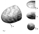
- the transducer arrangement of the torpedo sonar consists of 256 individual transducers (e) on the aerodynamically designed surface of the torpedo bow are provided. According to the selected nominal frequency of the sonar can also more or less individual transducers are used, for example at low nominal frequencies fewer converters or at higher nominal frequencies more converters. The number of converters (e) depends primarily on the spatial location area to be recorded.
- first zone (f) In the apex area of the torpedo bow there is a circular first zone (f), which in the shown case is not equipped with transducers. This will make the number of used Converter reduced. Reception converters in the crown zone (f) contribute little Direction formation of the sonar at. If, for example for target tracking, a directional beam head-on to be emitted by ultrasound waves, the apex zone (f) with several Transmitters provided. The other converters are mostly Receive converter or combined transmit / receive converter. When using pure Transmitter converters do not require the transmit / receive switch required for combined converters.
- the circular first zone (f) is followed by an annular second zone (g), which is connected with Transducers (e) is equipped.
- This second converter zone ensures a large and uniform Positioning angle range of the sonar both around the transverse axis and around the vertical axis of the Torpedoes.
- the rotationally symmetrical structure of the transducer arrangement ends with the ring zone (g).
- the third zone (h) To on both sides of the torpedo vertical axis there is a transition zone as the third zone (h), which is wider in the vicinity of the ring zone (g) than at the rear end.
- This third Zones lie axially symmetrical to the torpedo longitudinal axis.
- the two transition zones (h) convert the rotationally symmetrical location area into two lateral directional diagrams parallel to the longitudinal axis.
- the signals generated by the two side transducer arrangements can be evaluated more easily by a location processor than algorithms Output signals of a rotationally symmetrical converter arrangement.
- the end area of the converter zones is formed by two lateral fourth zones (i), which follow the transition zone (h) and extend to the great circle of the torpedo bow contour extend. They have a constant width and can, if necessary, also over continue the great circle towards the torpedo tail. These longitudinal zones (i) stretch that Directional diagram down to the rear of the torpedo. Only needs a horizontal one The angular position range of ⁇ 90 ° can be detected by equipping the fourth one Avoid zones (i) with converters. This reduces the number of converters required.
- the hydrodynamically predetermined torpedo contour from Apex of the torpedo bow starting in steps corresponding to half the acoustic nominal wavelength ⁇ of the torpedo sonar, i.e. in ⁇ / 2 steps, and thereby the axial, to determine the length of the individual converter zones measured along the torpedo contour.
- the ring-shaped second zone (g) in which several rings of transducers (e) enclose the longitudinal axis of the torpedo.
- the distance between neighboring transducer rings is ⁇ / 2.
- this second zone should end at about 5 ⁇ .
- the torpedo vertical axis is followed by a third zone (h), a transition area that extends up to a total distance of about 7 ⁇ is sufficient. It is wider than at the border to the second zone (g) at the rear end and leads on both sides of the torpedo into a fourth zone (i), which has a constant width.
- These longitudinal zones (i) extend at least to the largest Diameter of the torpedo bow, i.e. up to his great circle. This is where the cylindrical begins Torpedo contour.
- the two are used rotationally symmetrical converter zones (f) and (g) all-round localization based on the Torpedo longitudinal axis.
- the two axially symmetrical transducer zones (h) and (i) are used for location on both sides.
- the area of water above the torpedo should also be monitored be seen in a further development of the invention on the top as a fifth zone further transition zone corresponding to the structure of the third zone (h) and one itself subsequent sixth zone constructively corresponding to the fourth zone (i). Accordingly, you can add another fifth and sixth on the underside of the torpedo Attach the converter zone to locate the bottom of the water.
- the desired angular location ranges and the required angular resolution are the dimensions of the individual converter zones as well as the type, number and arrangement of the transducers in the zones.
Landscapes
- Engineering & Computer Science (AREA)
- Physics & Mathematics (AREA)
- Acoustics & Sound (AREA)
- Multimedia (AREA)
- Chemical & Material Sciences (AREA)
- Combustion & Propulsion (AREA)
- General Engineering & Computer Science (AREA)
- Astronomy & Astrophysics (AREA)
- Aviation & Aerospace Engineering (AREA)
- General Physics & Mathematics (AREA)
- Remote Sensing (AREA)
- Measurement Of Velocity Or Position Using Acoustic Or Ultrasonic Waves (AREA)
Abstract
Description
Fig.1 eine schematische Darstellung des Torpedobugs, und zwar
Claims (10)
- Torpedosonar mit einer Vielzahl an der gekrümmten Torpedobug-Oberfläche angeordneten elektroakustischen Wandlern (e), gekennzeichnet durch mehrere Wandlerzonen, nämlicha) eine rotationssymmetrisch den Scheitelpunkt des Torpedobugs umgebende, kreisförmige erste Zone (f);b) eine ringförmige, die erste Zone umgebende zweite Zone (g);c) zu beiden Seiten der Torpedohochachse je eine sich von der zweiten Zone nach hinten erstreckende dritte Zone (h), welche im Abstand vor dem Großkreis des Torpedobugs endet; undd) je eine seitliche vierte Zone (i), die sich von der dritten Zone bis zum Großkreis erstreckt.
- Torpedosonar nach Anspruch1, dadurch gekennzeichnet, daßa) die erste Zone (f) sich vom Scheitel des Torpedobugs bis zu einem Abstand von etwa 1,5λ erstreckt, wobei λ die akustische Nominalwellenlänge des Sonars ist;b) die zweite Zone (g) von 2λ bis etwa 5λ reicht; undc) die dritte Zone (h) sich bis etwa 7λ erstreckt.
- Torpedosonar nach Anspruch 1 oder 2, dadurch gekennzeichnet, daß die seitlichen vierten Zonen (i) sich nach achtern über den Großkreis hinaus erstrecken.
- Torpedosonar nach einem der Ansprüche 1 bis 3, dadurch gekennzeichnet, daß die seitlichen dritten Zonen (h) Übergangszonen sind, welche an der Grenze zur zweiten Zone (g) breiter sind als an der Grenze zur vierten Zone (i).
- Torpedosonar nach einem der Ansprüche 1 bis 4, dadurch gekennzeichnet, daß die seitlichen vierten Zonen (i) in Richtung der Torpedolängsachse eine gleichbleibende Breite haben.
- Torpedosonar nach einem der Ansprüche 1 bis 5, dadurch gekennzeichnet, daß die erste Zone (f) nicht mit Wandlern bestückt ist.
- Torpedosonar nach einem der Ansprüche 1 bis 5, dadurch gekennzeichnet, daß die erste Zone (f) mit Sendewandlern bestückt ist.
- Torpedosonar nach einem der Ansprüche 1 bis 7, dadurch gekennzeichnet, daß die vierten Zonen (i) nicht mit Wandlern bestückt sind.
- Torpedosonar nach einem der Ansprüche 1 bis 8, dadurch gekennzeichnet, daß auf der Torpedobug-Oberseite eine fünfte Zone vom Typ der dritten Zone sowie eine sechste Zone vom Typ der vierten Zone vorgesehen sind.
- Torpedosonar nach einem der Ansprüche 1 bis 9, dadurch gekennzeichnet, daß auf der Torpedobug-Unterseite eine fünfte Zone vom Typ der dritten Zone sowie eine sechste Zone vom Type der vierten Zone vorgesehen sind.
Applications Claiming Priority (2)
| Application Number | Priority Date | Filing Date | Title |
|---|---|---|---|
| DE10055164A DE10055164C1 (de) | 2000-11-08 | 2000-11-08 | Torpedosonar mit Schallwandlern |
| DE10055164 | 2000-11-08 |
Publications (3)
| Publication Number | Publication Date |
|---|---|
| EP1205260A2 true EP1205260A2 (de) | 2002-05-15 |
| EP1205260A3 EP1205260A3 (de) | 2003-12-03 |
| EP1205260B1 EP1205260B1 (de) | 2006-08-23 |
Family
ID=7662446
Family Applications (1)
| Application Number | Title | Priority Date | Filing Date |
|---|---|---|---|
| EP01126181A Expired - Lifetime EP1205260B1 (de) | 2000-11-08 | 2001-11-05 | Torpedosonar mit mehreren Wandlern |
Country Status (3)
| Country | Link |
|---|---|
| US (2) | US20020080685A1 (de) |
| EP (1) | EP1205260B1 (de) |
| DE (2) | DE10055164C1 (de) |
Families Citing this family (7)
| Publication number | Priority date | Publication date | Assignee | Title |
|---|---|---|---|---|
| AU2003904061A0 (en) * | 2003-08-01 | 2003-08-14 | Sonartech Atlas Pty Ltd | A sonar antenna |
| JP4605594B2 (ja) * | 2005-01-26 | 2011-01-05 | 古野電気株式会社 | 超音波送受波器および水中探知装置 |
| KR101174282B1 (ko) * | 2010-12-30 | 2012-08-16 | 국방과학연구소 | 음향 탐지 장치 |
| GB2550963B (en) * | 2016-06-03 | 2021-12-29 | Bae Systems Plc | Model-based protection algorithms |
| CN109031258B (zh) * | 2018-04-11 | 2023-05-02 | 哈尔滨工程大学 | 一种非对称式共形声基阵 |
| US12030603B2 (en) | 2020-04-24 | 2024-07-09 | Robert W. Lautrup | Modular underwater vehicle |
| US12228643B2 (en) | 2021-04-29 | 2025-02-18 | Deepsight Technology, Inc. | Modularized acoustic probe |
Citations (3)
| Publication number | Priority date | Publication date | Assignee | Title |
|---|---|---|---|---|
| US3906431A (en) | 1965-04-09 | 1975-09-16 | Us Navy | Search and track sonar system |
| DE3322246A1 (de) | 1982-06-22 | 1988-02-04 | France Etat | Sonarantenne, welche das angesetzte kopfstueck einer unterwasserrakete bildet, und verfahren zu ihrer herstellung |
| GB2234815B (en) | 1980-12-23 | 1991-07-10 | Honeywell Elac Nautik Ges Mit | Underwater target searching system |
Family Cites Families (8)
| Publication number | Priority date | Publication date | Assignee | Title |
|---|---|---|---|---|
| US3145679A (en) * | 1963-11-13 | 1964-08-25 | John D Brooks | Acoustic torpedo warhead and transducer apparatus |
| US3492634A (en) * | 1967-12-26 | 1970-01-27 | Dynamics Corp America | Conformal array of underwater transducers |
| US4253168A (en) * | 1978-10-23 | 1981-02-24 | Westinghouse Electric Corp. | CCD Signal processor |
| US4989530A (en) * | 1981-02-19 | 1991-02-05 | The United States Of America As Represented By The Secretary Of The Navy | Low drag homing torpedo nose assembly having side mounted planar arrays |
| US4449211A (en) * | 1982-07-06 | 1984-05-15 | The United States Of America As Represented By The Secretary Of The Navy | Low drag body conformal acoustic array |
| US5527480A (en) * | 1987-06-11 | 1996-06-18 | Martin Marietta Corporation | Piezoelectric ceramic material including processes for preparation thereof and applications therefor |
| US5602801A (en) * | 1995-12-06 | 1997-02-11 | The United States Of America As Represented By The Secretary Of The Navy | Underwater vehicle sonar system with extendible array |
| US5706253A (en) * | 1996-04-28 | 1998-01-06 | The United States Of America As Represented By The Secretary Of The Navy | Acoustic receiver array assembly |
-
2000
- 2000-11-08 DE DE10055164A patent/DE10055164C1/de not_active Expired - Fee Related
-
2001
- 2001-10-22 US US10/051,329 patent/US20020080685A1/en not_active Abandoned
- 2001-11-05 DE DE50110795T patent/DE50110795D1/de not_active Expired - Lifetime
- 2001-11-05 EP EP01126181A patent/EP1205260B1/de not_active Expired - Lifetime
-
2002
- 2002-12-11 US US10/316,390 patent/US6671229B2/en not_active Expired - Fee Related
Patent Citations (3)
| Publication number | Priority date | Publication date | Assignee | Title |
|---|---|---|---|---|
| US3906431A (en) | 1965-04-09 | 1975-09-16 | Us Navy | Search and track sonar system |
| GB2234815B (en) | 1980-12-23 | 1991-07-10 | Honeywell Elac Nautik Ges Mit | Underwater target searching system |
| DE3322246A1 (de) | 1982-06-22 | 1988-02-04 | France Etat | Sonarantenne, welche das angesetzte kopfstueck einer unterwasserrakete bildet, und verfahren zu ihrer herstellung |
Also Published As
| Publication number | Publication date |
|---|---|
| US20030117897A1 (en) | 2003-06-26 |
| DE10055164C1 (de) | 2002-11-28 |
| US20020080685A1 (en) | 2002-06-27 |
| EP1205260B1 (de) | 2006-08-23 |
| US6671229B2 (en) | 2003-12-30 |
| DE50110795D1 (de) | 2006-10-05 |
| EP1205260A3 (de) | 2003-12-03 |
Similar Documents
| Publication | Publication Date | Title |
|---|---|---|
| EP0268818B1 (de) | Vorrichtung zum Senden und Empfangen von Ultraschall-Signalen | |
| DE19853389A1 (de) | Bildgebung mit großer Apertur unter Verwendung eines Wandler-Arrays mit adaptiver Steuerung der Elementabstände | |
| DE68925100T2 (de) | Stosswellenerzeuger, der mit fokussierten Stosswellen in einem grossen Feld Konkremente zertrümmert | |
| DE2308443A1 (de) | Untersuchungsgeraet mit katheter zum untersuchen eines hohlen organes mit hilfe von ultraschallwellen und verfahren zum herstellen des katheters | |
| EP0040375B1 (de) | Ultraschallwandleranordnung | |
| DE102010056119B4 (de) | Akustische Unterwasserantenne, U-Boot mit derartiger Antenne sowie Verfahren zum Peilen, Orten und/oder Klassifizieren eines Ziels mittels einer derartigen Antenne | |
| WO2024056239A1 (de) | Sonarsystem | |
| EP1205260B1 (de) | Torpedosonar mit mehreren Wandlern | |
| DE69617390T2 (de) | Gerichtete wandleranordnung mit hoher verstärkung | |
| DE60124314T2 (de) | Rumpfsonar für seeschiff | |
| DE4327841C1 (de) | Elektroakustisches Unterwasser-Peilgerät | |
| WO2023232535A1 (de) | Hydroakustisches schallsenderarray | |
| DE69417639T2 (de) | Therapiegerät mit variabler fokussierung ohne sekundärfokussierung | |
| DE2615973A1 (de) | Verringerung der seitenmaxima bei ultraschall-echolotverfahren | |
| DE69402696T2 (de) | Vorrichtung zum aufspüren im boden eingebetteter objekte | |
| EP1902330B1 (de) | Vorrichtung zum bestimmen der eigengeschwindigkeit eines wasserfahrzeugs | |
| EP1901857B1 (de) | Unterwasserantenne mit einer aus einer mehrzahl von elektroakustischen wandlern bestehenden wandleranordnung | |
| DE3833272B3 (de) | Entfaltbares zylindrisches Sonar | |
| EP4178731B1 (de) | Wasserschallwandler mit einer gerichteten strahlungscharakteristik | |
| DE1548516B2 (de) | Schall-Ortungseerät | |
| DE19910037C2 (de) | Elektroakustisches Unterwasser-Ortungsgerät | |
| DE102023111721A1 (de) | Schleppsonar | |
| EP4649332A1 (de) | Informationssystem für ein unterwasserfahrzeug zur bestimmung von navigationsinformationen mittels sonar | |
| WO2024149598A1 (de) | Informationssystem für ein unterwasserfahrzeug zur bestimmung von navigationsinformationen mittels sonar | |
| WO2024149600A1 (de) | Wasserschallgenerator zum bereitstellen eines sendesignals für ein sonar |
Legal Events
| Date | Code | Title | Description |
|---|---|---|---|
| PUAI | Public reference made under article 153(3) epc to a published international application that has entered the european phase |
Free format text: ORIGINAL CODE: 0009012 |
|
| AK | Designated contracting states |
Kind code of ref document: A2 Designated state(s): AT BE CH CY DE DK ES FI FR GB GR IE IT LI LU MC NL PT SE TR |
|
| AX | Request for extension of the european patent |
Free format text: AL;LT;LV;MK;RO;SI |
|
| PUAL | Search report despatched |
Free format text: ORIGINAL CODE: 0009013 |
|
| AK | Designated contracting states |
Kind code of ref document: A3 Designated state(s): AT BE CH CY DE DK ES FI FR GB GR IE IT LI LU MC NL PT SE TR |
|
| AX | Request for extension of the european patent |
Extension state: AL LT LV MK RO SI |
|
| RIC1 | Information provided on ipc code assigned before grant |
Ipc: 7B 06B 1/06 A Ipc: 7G 10K 11/00 B |
|
| 17P | Request for examination filed |
Effective date: 20040109 |
|
| AKX | Designation fees paid |
Designated state(s): DE FR GB IT SE |
|
| GRAP | Despatch of communication of intention to grant a patent |
Free format text: ORIGINAL CODE: EPIDOSNIGR1 |
|
| GRAS | Grant fee paid |
Free format text: ORIGINAL CODE: EPIDOSNIGR3 |
|
| GRAA | (expected) grant |
Free format text: ORIGINAL CODE: 0009210 |
|
| AK | Designated contracting states |
Kind code of ref document: B1 Designated state(s): DE FR GB IT SE |
|
| PG25 | Lapsed in a contracting state [announced via postgrant information from national office to epo] |
Ref country code: IT Free format text: LAPSE BECAUSE OF FAILURE TO SUBMIT A TRANSLATION OF THE DESCRIPTION OR TO PAY THE FEE WITHIN THE PRESCRIBED TIME-LIMIT;WARNING: LAPSES OF ITALIAN PATENTS WITH EFFECTIVE DATE BEFORE 2007 MAY HAVE OCCURRED AT ANY TIME BEFORE 2007. THE CORRECT EFFECTIVE DATE MAY BE DIFFERENT FROM THE ONE RECORDED. Effective date: 20060823 |
|
| REG | Reference to a national code |
Ref country code: GB Ref legal event code: FG4D Free format text: NOT ENGLISH |
|
| REF | Corresponds to: |
Ref document number: 50110795 Country of ref document: DE Date of ref document: 20061005 Kind code of ref document: P |
|
| REG | Reference to a national code |
Ref country code: SE Ref legal event code: TRGR |
|
| GBT | Gb: translation of ep patent filed (gb section 77(6)(a)/1977) |
Effective date: 20061109 |
|
| ET | Fr: translation filed | ||
| PLBE | No opposition filed within time limit |
Free format text: ORIGINAL CODE: 0009261 |
|
| STAA | Information on the status of an ep patent application or granted ep patent |
Free format text: STATUS: NO OPPOSITION FILED WITHIN TIME LIMIT |
|
| 26N | No opposition filed |
Effective date: 20070524 |
|
| REG | Reference to a national code |
Ref country code: FR Ref legal event code: PLFP Year of fee payment: 15 |
|
| REG | Reference to a national code |
Ref country code: FR Ref legal event code: PLFP Year of fee payment: 16 |
|
| PGFP | Annual fee paid to national office [announced via postgrant information from national office to epo] |
Ref country code: GB Payment date: 20161128 Year of fee payment: 16 Ref country code: FR Payment date: 20161127 Year of fee payment: 16 |
|
| PGFP | Annual fee paid to national office [announced via postgrant information from national office to epo] |
Ref country code: IT Payment date: 20161130 Year of fee payment: 16 Ref country code: SE Payment date: 20161127 Year of fee payment: 16 |
|
| PGFP | Annual fee paid to national office [announced via postgrant information from national office to epo] |
Ref country code: DE Payment date: 20171207 Year of fee payment: 17 |
|
| REG | Reference to a national code |
Ref country code: SE Ref legal event code: EUG |
|
| GBPC | Gb: european patent ceased through non-payment of renewal fee |
Effective date: 20171105 |
|
| PG25 | Lapsed in a contracting state [announced via postgrant information from national office to epo] |
Ref country code: SE Free format text: LAPSE BECAUSE OF NON-PAYMENT OF DUE FEES Effective date: 20171106 |
|
| REG | Reference to a national code |
Ref country code: FR Ref legal event code: ST Effective date: 20180731 |
|
| PG25 | Lapsed in a contracting state [announced via postgrant information from national office to epo] |
Ref country code: FR Free format text: LAPSE BECAUSE OF NON-PAYMENT OF DUE FEES Effective date: 20171130 Ref country code: IT Free format text: LAPSE BECAUSE OF NON-PAYMENT OF DUE FEES Effective date: 20171105 |
|
| REG | Reference to a national code |
Ref country code: DE Ref legal event code: R082 Ref document number: 50110795 Country of ref document: DE Representative=s name: LOBEMEIER, MARTIN LANDOLF, DR., DE |
|
| PG25 | Lapsed in a contracting state [announced via postgrant information from national office to epo] |
Ref country code: GB Free format text: LAPSE BECAUSE OF NON-PAYMENT OF DUE FEES Effective date: 20171105 |
|
| REG | Reference to a national code |
Ref country code: DE Ref legal event code: R119 Ref document number: 50110795 Country of ref document: DE |
|
| PG25 | Lapsed in a contracting state [announced via postgrant information from national office to epo] |
Ref country code: DE Free format text: LAPSE BECAUSE OF NON-PAYMENT OF DUE FEES Effective date: 20190601 |