Technical Field
-
The present invention relates to a precipitation tube
for centrifugal separation (hereinafter referred to as
"centrifugal precipitation tube") used in the case when a
liquid mixture to be separable into two or more liquid phases
is separated due to difference in specific gravity utilizing
centrifugal force.
Background Art
-
In the case of measuring, for example, a concentration
of a medicament contained in a serum, the medicament in the
serum is extracted by means of chloroform. In this case,
it has been conventional that a buffer solution is applied
to the serum, and a liquid mixture with chloroform added
further thereto is thoroughly shaken. Subsequently, the
liquid mixture is separated without delay into a water phase
(upper layer liquid) and a chloroform phase (lower layer
liquid) using a centrifugal separator, and only a
predetermined volume of the chloroform phase is sampled.
Thus, in the case that a liquid mixture separable into two
liquid phases using a centrifugal separator, such as a liquid
mixture of water and organic solvent, is separated into an
upper layer liquid and a lower layer liquid due to difference
in specific gravity, a centrifugal precipitation tube has
been heretofore used. Such a conventional centrifugal
precipitation tube consists of a tubular vessel body with
its upper surface opened and a cap for closing the opening
on the upper surface of the vessel body in a liquid-tight
manner. In order to separate a liquid mixture into an upper
layer liquid and a lower layer liquid using this centrifugal
precipitation tube, the liquid mixture is injected into the
vessel body, the cap is tightly fitted onto the upper surface
opening of the vessel body. Then, the centrifugal
precipitation tube is subjected to a centrifugal separator,
whereby the liquid mixture within the centrifugal
precipitation tube is separated into the upper layer liquid
and the lower layer liquid due to difference in specific
gravity. In order to take out only the lower layer liquid
separately from the upper layer liquid and the lower layer
liquid separated in the centrifugal precipitation tube by
centrifugal force, it has been generally conducted that,
using a syringe, the upper layer liquid is entirely sucked
through a suction nozzle and taken out of the internal part
of the vessel body. Alternatively, in the case of taking
out the upper layer liquid manually, it has been generally
conducted that, using a hole pipette, a pipette or the like,
the upper layer liquid is entirely removed from the internal
part of the vessel body while visually acknowledging a
boundary (interface) between the upper layer liquid and the
lower layer liquid, thereby only the lower layer liquid being
left in the vessel body.
-
In the mentioned known method, however, that the upper
layer liquid is entirely sucked through the suction nozzle
by means of the syringe and removed out of the internal part
of the vessel body, a problem exists in that a liquid flow
is generated at the time of sucking the upper layer liquid
by the suction nozzle, whereby a part of the upper layer
liquid is mixed into the lower layer liquid and it becomes
difficult to remove only the upper layer liquid. On the other
hand, in the method of manual operation using a hole pipette
or the like, a problem exists in that it requires experience
and skill for removing only the upper layer liquid from the
internal part of the vessel body, because a part of the upper
layer liquid is likely to mix with the lower layer liquid
depending on kind of liquid when the upper layer liquid has
been taken out to the proximity of the boundary between the
upper layer liquid and the lower layer liquid.
-
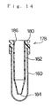
To overcome the foregoing disadvantages, a centrifugal
precipitation tube has been proposed as disclosed in Figs.
12 and 14 each showing a longitudinal sectional view of the
Japanese Patent Publication (unexamined) No. 285740/1997.
This is a centrifugal precipitation tube in which a cap 162
or 178 for closing in a liquid-tight manner an opening on
the upper surface of a tubular vessel body provided with
a bottom is comprised of a seal plug part 164 or 180, an
internal tube 166 or 182, and a closure part 168 or 184.
The seal plug part 164 or 180 of the centrifugal precipitation
tube is inserted into an upper end portion of the vessel
body 160 to tightly fit an outer peripheral surface thereof.
A through hole 170 or 186 is formed at the central portion
of the seal plug part 164 or 180. The internal tube 166 or
182 includes an outer diameter smaller than an inner diameter
of the vessel body 160 and is formed into a tubular shape
of which lower portion is tapered. An upper end portion of
the internal tube 166 or 182 is fixed to an inner peripheral
portion of the through hole 170 or 186 and formed integral
with the seal plug part 164 or 180. Further, the internal
tube 166 or 182 is formed to have a length such that lower
end thereof comes located in the proximity of inner bottom
face of the vessel body 160 when fitting the seal plug part
164 or 180 tightly against the upper end portion of the vessel
body 160. A closure part 168 of the centrifugal
precipitation tube shown in Fig. 12 is comprised of a plug
that is upwardly inserted into a lower end opening of the
internal tube 166 and closes the lower end opening of the
internal tube 166 in a liquid-tight manner. This closure
part 168 is formed so as to easily come off or gets out
downwardly by means of a downward pressure force, i.e., a
downwardly force applied by the lower end of a dispensing
nozzle or pipette. Furthermore, a closure part 184 of the
centrifugal precipitation tube shown in Fig. 14 is comprised
of a thin plate-like part integrally molded at lower end
of the internal tube 182. This closure part 184 is easily
broken by being downwardly pressed with the lower end of
a dispensing nozzle or pipette.
-
In the centrifugal precipitation tube shown in Figs.
12 and 14, a liquid to be separated by means of a centrifugal
force is injected into the vessel body 160 of the centrifugal
precipitation tube. Then, the internal tube 166 or 182 of
the cap 162 or 178 is deeply put in the vessel body 160,
i.e., inserted into the liquid so that the seal plug part
164 or 180 of the cap 162 or 178 tightly fits the upper end
portion of the vessel body 160. The centrifugal
precipitation tube in this state is subjected to a centrifugal
separator. In this manner, the liquid in the centrifugal
precipitation tube is separated into an upper layer liquid
and a lower layer liquid. At this time, since the internal
tube 166 or 182 of the cap 162 or 178 is inserted into the
liquid in the vessel body 160 and the lower end of the internal
tube 166 or 182 is positioned in the proximity of inner bottom
face of the vessel body 160, the lower end of the internal
tube 166 or 182 is closed in a liquid-tight manner and
positioned below the boundary between the upper layer liquid
and the lower layer liquid. Thus, a portion proximate to
the lower end of the internal tube 166 or 182 is in the state
of being inserted into the lower layer liquid. In order to
extract only the lower layer liquid from the centrifugal
precipitation tube in such a state, the lower end portion
of the dispensing nozzle (or disposable chip forming the
lower end portion of the dispensing nozzle) or a pipette
is deeply inserted into the internal part of the internal
tube 166 or 182 passing a through hole of the seal plug part
164 or 180 of the cap 162 or 178, and the closure part 168
or 184 at the lower end of the internal tube 166 or 182 is
downwardly pressed by means of the lower end of the dispensing
nozzle or pipette. As a result, the closure part 168 or 184
for closing the lower end of the internal tube 166 or 182
gets off or broken and the lower end of the dispensing nozzle
or pipette is inserted into the lower layer liquid.
Thereafter, a liquid is sucked into the dispensing nozzle
by driving the syringe. Alternatively, when manually
operating the pipette and sucking the liquid into the pipette,
only the lower layer liquid is sucked into the dispensing
nozzle or pipette since the lower end of the dispensing nozzle
or pipette is inserted into the lower layer liquid.
-
In the centrifugal precipitation tube shown in Figs.
12 and 14, however, after the separation of liquid into the
upper layer liquid and the lower layer liquid, the closure
part 168 or 184 at the lower end of the internal tube 166
or 182 is downwardly pressed by means of the lower end of
a dispensing nozzle or pipette, and the closure part 168
or 184 for closing the lower end of the internal tube 166
or 182 comes off or broken. At this time, it is to be noted
that the lower layer liquid is flushed into the internal
tube 166 or 182, whereby a boundary between an upper layer
liquid and a lower layer liquid is disturbed. Thus, a part
of the upper layer liquid is mixed into the lower layer liquid
side, and the upper layer liquid together with the lower
layer liquid is flushed into the internal tube 166 or 182.
As a result, there is a likelihood that the lower layer liquid
being mixed with a part of the upper layer liquid is sucked
into a dispensing nozzle or pipette, and a contamination
is produced in the lower layer liquid.
-
Further, in the centrifugal precipitation tube shown
in Fig. 12, as described with reference to Fig. 13, after
the separation of a liquid into the upper layer liquid 172
and the lower layer liquid 174, the closure part 168 at the
lower end of the internal tube 166 is pressed downward by
the lower end of the dispensing nozzle 176, and the closure
part 168 closing the lower end of the internal tube 166 is
caused to come off. At this time, the closure part 168 sinks
vertically right under the lower end of the internal tube
166 and left on the inner bottom face of the vessel body
160 in the same posture since the lower surface of the closure
plug 168 is flat. Therefore, when inserting the dispensing
nozzle 176 deeply to the extent that the lower end thereof
comes in the proximity of the inner bottom face of the vessel
body 160, the lower end face of the dispensing nozzle 176
comes in close contact with the upper surface of the closure
plug 168, and the lower end opening of the dispensing nozzle
176 is entirely closed by the closure plug 168. As a result,
a liquid will not be sucked into the dispensing nozzle 176.
Particularly in the case of automating the operation of
sucking the liquid into the dispensing nozzle 176 by driving
up-and-down the dispensing nozzle 176, this becomes a serious
problem.
-
Furthermore, before the centrifugal precipitation tube
is subjected to the centrifugal separator, when the internal
tube 166 is deeply put in the vessel body 160 and inserted
into the liquid after injection of the liquid into the vessel
body 160, the liquid flows in such a manner as being pressed
away by means of the lower surface of the closure part 168
plugged in the lower end opening of the internal tube 166.
In this case, supposing that the lower surface of the closure
part 168 is flat as shown in Fig. 12, when the lower end
portion of the internal tube 166 is passed through the boundary
between, for example, a water phase and a chloroform phase
(this mixed solution is separated into two phases to a certain
degree due to difference in specific gravity even before
the centrifugal separation), the lower surface of the closure
part 168 comes in contact with impurities located at the
boundary, and therefore the liquid is subjected to the
centrifugal separation with impurities being stuck to the
lower surface of the closure part 168. Then, the lower layer
liquid 174 having been separated by means of centrifugal
separation comes in contact with the lower surface of the
closure part 168. As a result, the impurities stuck to the
lower surface of the closure part 168 come to be dispersed
into the lower layer liquid to be extracted and analyzed.
Thus, negative affects are given upon device analysis.
Disclosure of Invention
-
The present invention was made in view of the
above-discussed problems. A first object of the invention
is to provide a centrifugal precipitation tube capable of
extracting exactly only a lower layer liquid without any
contamination from two-phase liquid (or more numbers of phase
liquid) separated into an upper layer liquid and a lower
layer liquid by means of centrifugal force. A second object
of the invention is to provide a centrifugal precipitation
tube capable of exactly sucking a lower layer liquid into
a dispensing nozzle or pipette constantly at all times, and
preventing a lower surface of a closure part of an internal
tube from sticking of impurities in the process of inserting
the internal tube into liquid by deeply placing it in a vessel
body after injection of liquid into the vessel body.
-
To accomplish the foregoing first object, a centrifugal
precipitation tube according to a first invention comprises:
a tubular vessel body of which top end is opened while bottom
end thereof being closed; and seal means for closing
releasably the open top end of the vessel body in a
liquid-tight manner;
the centrifugal precipitation tube being
characterized in that: an internal tube, diameter of which
is smaller than that of the mentioned vessel body, is inserted
in an internal part of the vessel body and secured thereto,
whereby a centrifugal separation chamber is formed between
inner peripheral surface of the vessel body and outer
peripheral surface of the internal tube, and an upper portion
and a lower portion of the centrifugal separation chamber
are respectively communicated to an extraction chamber
inside of the mentioned internal tube; a piston plug, lower
end portion of which is inserted in the proximity of an inner
bottom face of the mentioned vessel body, is slidably and
removably inserted into the mentioned internal tube in axial
direction thereof; communications between the upper and
lower portions of the mentioned centrifugal separation
chamber and the mentioned extraction chamber are
respectively interrupted when inserting the mentioned piston
plug into the innermost area of the mentioned internal tube;
and an upper space of the mentioned centrifugal separation
chamber and a space on the lower end face side of the piston
plug in the mentioned extraction chamber are communicated
to each other during the process of pulling out the mentioned
piston plug from the state of being inserted in the innermost
area of the mentioned internal tube.
-
In the centrifugal precipitation tube of above
construction according to the first invention, a liquid to
be separated by means of centrifugal force is injected into
the vessel body of the centrifugal precipitation tube, then
the piston plug is inserted into the innermost area of the
internal tube, top opening of the vessel body is closed in
a liquid-tight manner by the seal means, and the centrifugal
precipitation tube in this state is subjected to a centrifugal
separator. At this time, the lower end portion of the piston
plug is inserted in the proximity of inner bottom face of
the vessel body, whereby the liquid remaining in the
extraction chamber inside of the internal tube is entirely
extruded therefrom to the lower part of the centrifugal
separation chamber between the inner peripheral surface of
the vessel body and the outer peripheral surface of the
internal tube. Further, since the communication between the
upper and lower portions of the centrifugal separation
chamber and the extraction chamber is interrupted during
the centrifugal separation, any liquid does not flow from
the centrifugal separation chamber into the extraction
chamber. Then, the liquid in the centrifugal precipitation
tube is separated into an upper layer liquid and a lower
layer liquid in the centrifugal separation chamber due to
difference in specific gravity. At that time, by
appropriately setting position of the lower end of the
internal tube, the lower end of the internal tube is positioned
below the boundary between the upper layer liquid and the
lower layer liquid, and the lower end of the internal tube
is in the state of being immersed in the lower layer liquid.
-
In order to extract only the lower layer liquid from
a centrifugal precipitation tube after the liquid is
separated into upper layer liquid and lower layer liquid
in the precipitation tube by means of the centrifugal
separator, top opening of the vessel body that_has been closed
by the seal means is opened and the piston plug is slowly
pulled out from the internal tube. As a result, the lower
layer liquid in the centrifugal separation chamber is slowly
sucked into the extraction chamber inside of the internal
tube. In this regard, supposing that the liquid from the
centrifugal separation chamber to the extraction chamber
be continuously sucked, not only the lower layer liquid but
also the upper layer liquid will flow into the extraction
chamber, and a part of the upper layer liquid will be mixed
into the lower layer liquid in the extraction chamber, whereby
contamination will take place in the lower layer liquid.
In this centrifugal precipitation tube, however, the upper
space of the centrifugal separation chamber and the space
on the side of the lower end face of the piston plug are
communicated during the process of pulling out the piston
plug. Accordingly, an equal air pressure is applied onto
the liquid surface of lower layer liquid in the extraction
chamber and the liquid surface of upper layer liquid in the
centrifugal separation chamber, respectively. Therefore,
even if the piston plug would be further pulled out, it is
prevented that the lower layer liquid in the extraction
chamber is sucked upward by means of the piston plug.
-
As described above, in the precipitation tube of above
construction, since the lower layer liquid in the centrifugal
separation chamber is slowly sucked into the extraction
chamber inside of the internal tube by means of the piston
plug, it does not occur that the boundary between the upper
layer liquid and the lower layer liquid in the centrifugal
separation chamber is disturbed, thereby a part of the upper
layer liquid being mixed into the side of the lower layer
liquid, and the upper layer liquid together with lower layer
liquid flow into the extraction chamber inside of the internal
tube. Further, by appropriately setting a pull-up position
of the piston plug at the time of communicating the upper
space of the centrifugal separation chamber to space on the
side of lower end face of the piston, it does not occur,
either, that the lower layer liquid as well as the upper
layer liquid flow into the extraction chamber, and a part
of the upper layer liquid is mixed into the lower layer liquid.
Consequently, only the lower layer liquid will remain or
be accumulated in the extraction chamber when the piston
plug is completely pulled out from the internal tube. The
lower layer liquid remaining in the extraction chamber is
sucked into a dispensing nozzle by driving a syringe or the
like after deeply placing, e.g., lower end portion of the
dispensing nozzle (pipette or the like in the case of manual
operation. Utilization of the dispensing nozzle is
hereinafter described) in the internal tube, thereby
inserting the lower end of the dispensing nozzle into the
lower layer liquid. At this time, by appropriately setting
the position of the lower end of the internal tube, the lower
end of the internal tube becomes in the state of being
positioned below the boundary between the upper layer liquid
and the lower layer liquid, even after a predetermined volume
of lower layer liquid has been sucked into the dispensing
injection nozzle.
-
In this manner, as a result of using a centrifugal
precipitation tube according to the first invention, only
the lower layer liquid can be reliably extracted, without
any occurrence of contamination involving the upper layer
liquid, from two or more liquid phases separated into the
upper layer liquid and lower layer liquid by means of the
centrifugal force.
-
In the centrifugal precipitation tube according to the
first invention, it is preferable that the seal means and
the piston plug are communicated to each other.
-
In the centrifugal precipitation tube of such
construction, since the seal means and the piston plug are
integrated with each other, the piston plug is deeply inserted
into the innermost area of the internal tube when the top
opening of the vessel body is closed in a liquid-tight manner
by the seal means. And the piston plug is pulled out from
the state of being inserted into the innermost area of the
internal tube when pulling up the seal means after the top
opening of the vessel body having been closed by the seal
means is opened. As a result, operation of the centrifugal
precipitation tube can be simply conducted.
-
Further, in the centrifugal precipitation tube
according to the first invention, it is preferable that a
seal member, coming in close contact with the inner peripheral
surface of the internal tube in a liquid-tight manner when
the piston plug is inserted and fitted into the internal
tube, is mounted on and secured to the external peripheral
surface of the mentioned piston plug.
-
In the centrifugal precipitation tube of such
construction, when inserting the piston plug into the
innermost area of the internal tube, the seal member inserted
and secured on the external peripheral surface of the piston
plug comes in close contact with the inner peripheral surface
of the internal tube in a liquid-tight manner, thereby a
communication between the upper portion of the centrifugal
separation chamber and the extraction chamber is interrupted
without fail.
-
Further, in the centrifugal precipitation tube
according to the first invention, it is preferable that the
upper end face of the internal tube is opened in the internal
part of the vessel body so that upper portion of the
centrifugal separation chamber and the extraction chamber
inside of the internal tube are communicated to each other,
and a slot is formed in the internal part of the piston plug
in such a manner as to be opened at a lower end face and
at an external peripheral surface of the piston plug.
-
In the centrifugal precipitation tube of such
construction, the opening in the external peripheral surface
of the piston plug of the slot formed in the internal part
of the piston plug passes over the upper end of the internal
tube during the process in which the mentioned piston plug
is pulled out from the state of being inserted in the innermost
area of the mentioned internal tube, whereby the upper portion
of the centrifugal separation chamber and space on the side
of lower end face of the piston plug in the extraction chamber
are communicated to each other without fail through the slot
of the piston plug.
-
Further, in the centrifugal precipitation tube
according to the first invention, it is preferable that the
internal tube is provided with a communication aperture so
that upper portion of the centrifugal separation chamber
and the extraction chamber inside of the internal tube are
communicated to each other through the communication
aperture, a slot opened at the lower end face and external
peripheral surface of the piston plug is formed in the internal
part of the piston plug, and a groove or a concave-surface
part communicating to the mentioned slot is formed on the
external peripheral surface of the piston plug.
-
In the centrifugal precipitation tube of such
construction, during the process in which the mentioned
piston plug is pulled out from the state of being inserted
in the innermost area of the mentioned internal tube, the
upper end portion of the groove or the concave-surface part
provided on the external peripheral surface of the piston
plug passed over the communication aperture opened in the
internal tube, whereby upper portion of the centrifugal
separation chamber and space on the side of lower end face
of the piston plug are communicated to each other without
fail through the communication aperture in the internal tube,
through a clearance between the groove or concave-surface
part on the external peripheral surface of the piston plug
and inner peripheral surface of the internal tube and through
the slot in the piston plug.
-
Further, in the centrifugal precipitation tube
according to the first invention, it is preferable that the
internal tube is formed so that inner diameter of upper side
portion thereof is larger than that of the lower end portion.
-
In the centrifugal precipitation tube of such
construction, the communication of each of lower and upper
portions of the centrifugal separation chamber between the
inner peripheral surface of the vessel body and outer
peripheral surface of the internal tube to the extraction
chamber inside of the internal tube is interrupted when
inserting the piston plug into the innermost area of the
internal tube. Whereas during the process in which the
mentioned piston plug is pulled out from the state of being
inserted in the innermost area of the mentioned internal
tube, a clearance is formed between the external peripheral
surface of the lower end portion of the piston plug and inner
peripheral surface of the internal tube with its inner
diameter enlarged, whereby upper space of the centrifugal
separation chamber and space on the side of the lower end
face of the piston plug in the extraction chamber becomes
communicated to each other without fail through the mentioned
clearance.
-
To accomplish the foregoing first and second objects,
a centrifugal precipitation tube according to a second
invention comprises: a tubular vessel body of which top end
is opened while bottom end thereof being closed; an internal
tube being tubular shaped and having an outer diameter smaller
than inner diameter of the mentioned vessel body, and which
is inserted into the internal part of the vessel body and
held so that lower end of the internal tube is positioned
in the proximity of the inner bottom face of the vessel body;
a closure plug which is detachably fitted to lower end portion
of the mentioned internal tube, closes lower end opening
of the internal tube in a liquid-tight manner, and easily
comes off from the lower end portion of the internal tube
by downward pressure force; and seal means for sealing a
centrifugal separation chamber formed between inner
peripheral surface of the mentioned vessel body and outer
peripheral surface of the mentioned internal tube;
the centrifugal precipitation tube being
characterized in that: the lower surface side of the mentioned
closure plug is formed into such a configuration that the
closure plug comes off from the lower end portion of the
mentioned internal tube and falls down in any one of forward,
reward, leftward and rightward directions from the coming
off position upon reaching the inner bottom face of the
mentioned vessel body.
-
In the centrifugal precipitation tube of above
construction according to the second invention, a liquid
to be separated by means of centrifugal force is inserted
into the vessel body, then the internal tube is deeply put
in the vessel body and inserted into the liquid, and a
centrifugal separation chamber formed between the inner
peripheral surface of the vessel body and outer peripheral
surface of the internal tube is sealed by the seal means.
The centrifugal precipitation tube in this state is subjected
to a centrifugal separator. By means of a centrifugal
separator, the liquid in the centrifugal precipitation tube
is separated into an upper layer liquid and a lower layer
liquid due to difference in specific gravity. At that time,
since the internal tube is inserted into the liquid in the
vessel body and lower end of the internal tube is positioned
in the proximity of inner bottom face of the vessel body,
the lower end of the internal tube being closed in a
liquid-tight manner is positioned below a boundary between
the upper layer liquid and lower layer liquid. And the
portion proximate to the lower end of the internal tube is
in the state of being inserted into the lower layer liquid.
In order to extract only the lower layer liquid from the
centrifugal precipitation tube in such a state, lower end
portion of a dispensing nozzle is deeply put in the internal
tube inwardly, and a closure plug at the lower end of the
internal tube is downwardly pressed by lower end of the
dispensing nozzle. Therefore, the closure plug having
closed the lower end of the internal tube comes off and the
lower end of the dispensing nozzle is inserted into the lower
layer liquid. The closure plug having come off from the lower
end of the internal tube sinks right downwardly below the
lower end opening of the internal tube. Then, the closure
plug having reached to the inner bottom face of the vessel
body falls down in any one of forward, rearward, leftward
and rightward directions from the coming off position.
Consequently, even if lower end of the dispensing nozzle
is put in the proximity of inner bottom face of the vessel
body, it does not occur that the lower end of the dispensing
nozzle comes in close contact with the closure plug and the
lower end opening of the dispensing nozzle is entirely closed
by means of the closure plug. As a result, the lower layer
liquid is sucked without fail into the dispensing nozzle.
-
In this manner, when using the centrifugal
precipitation tube according to the second invention, the
lower layer liquid can be constantly sucked into the
dispensing nozzle or pipette at all times from two or more
liquid phases separated into the upper layer liquid and the
lower layer liquid. Accordingly, only the lower layer liquid
can be exactly extracted without any contamination with the
upper layer liquid. Further, operation fault can be
prevented particularly in the case of automating the sucking
operation of liquid into the dispensing nozzle by driving
up and down the separating injection nozzle.
-
In the centrifugal precipitation tube according to the
second invention, it is preferable that lower surface side
of the mentioned closure plug is formed into a conical or
pyramidal shape.
-
In the centrifugal precipitation tube of such
construction, the closure plug disengaged from lower end
portion of the internal tube and reached to the inner bottom
face of the vessel body is formed so that the lower surface
side of the closure plug is a conic shape. Accordingly, the
closure plug falls down without fail in any one of forward,
rearward, leftward and rightward directions. Consequently,
even if lower end of the dispensing nozzle is put in the
proximity of inner bottom face of the vessel body, it does
not occur that the lower end of the dispensing nozzle comes
in close contact with the closure plug and the lower end
opening of the dispensing nozzle is entirely closed by means
of the closure plug.
-
Further, when injecting a liquid into the vessel body
and placing the internal tube deeply in the vessel body to
insert it into the liquid, the liquid flows so as to be pushed
away by means of the lower surface side of the closure plug
inserted in the lower end opening of the internal tube.
However, since the lower surface side of the closure plug
is formed into a conic shape, even if the lower surface side
of the closure plug comes in contact with the impurities
when lower end portion of the internal tube passes over the
boundary between, for example, a water phase and a chloroform
phase, impurities flow upwardly along the conic-shaped lower
surface side of the closure plug together with the liquid
and do not stick to the lower surface side of the closure
plug. As a result, it is prevented that impurities stuck
to the lower surface side of the closure plug is dispersed
into the lower layer liquid separated due to centrifugal
force, and reliability in results of analysis of equipment
can be improved.
-
Further, in the centrifugal precipitation tube of above
construction, it is preferable that a flange that comes in
close contact with the upper edge portion of said vessel
body either by interposition of a liquid-tight seal member
or by direct engagement is formed on an upper end portion
of said internal tube; a thread part is formed on an outer
peripheral surface of the upper end portion of the mentioned
vessel body; and seal means is formed by a cap having a thread
part to be mounted on the upper end portion of the mentioned
vessel body and screw threaded into the mentioned thread
part, and which is provided with a through hole at the central
portion of an upper surface; in which, by screw threading
the cap into the upper end portion of the vessel body, a
centrifugal separation chamber formed between inner
peripheral surface of the vessel body and outer peripheral
surface of the mentioned internal tube is sealed in an
air-tight manner, while, by loosing the cap, the centrifugal
separation chamber is communicated to outside air.
-
In the centrifugal precipitation tube of such
construction, to conduct a centrifugal separation of a liquid
by means of a centrifugal separator, the liquid is injected
into the vessel body in the state of pulled out the internal
tube from the vessel body, then the internal tube is inserted
into the internal part of the vessel body, and subsequently
the cap is mounted on the upper end portion of the vessel
body and screw-threaded thereinto. Thus, the flange part
of the upper end portion of the internal tube is pressed
onto the upper edge of the vessel body either through the
liquid-tight seal member or directly by means of the
peripheral edge portion of the through hole on the upper
surface of the cap. Accordingly, the flange part of the
internal tube and the upper edge of the vessel body comes
in close contact with each other. Thus, the centrifugal
separation chamber between the inner peripheral surface of
the vessel body and the outer peripheral surface of the
internal tube comes to be sealed in an air-tight manner and
in a liquid-tight manner. Further, when the lower layer
liquid is extracted from the internal part of the centrifugal
precipitation tube after conducting the centrifugal
separation, the cap mounted on the upper end portion of the
vessel body is loosened. Consequently, the sealed state
between the flange of the internal tube and the top edge
of the vessel body is released, and the centrifugal separation
chamber communicates to the outside air through a clearance
between the inner peripheral surface of the upper portion
of the vessel body and the outer peripheral surface of the
upper portion of the internal tube as well as through a
clearance between the flange part of the internal tube and
the top edge of the vessel body. As a result, there is no
more such trouble that, when the closure plug at the lower
end portion of the internal tube is subsequently pressed
downward by the lower end of the dispensing nozzle for coming
off, the lower layer liquid is flushed into the internal
tube due to a gas pressure from gaseous phase portion, thereby
disturbing boundary between the upper layer liquid and the
lower layer liquid, a part of the upper layer liquid being
mixed into the lower layer liquid side, and the upper layer
liquid together with the lower layer liquid flow into the
internal tube. Thus, only the lower layer liquid can be
exactly extracted without contamination with the upper layer
liquid.
Brief Description of Drawings
-
- Fig. 1 shows a preferred embodiment of the first
invention and is a front view in which a centrifugal
precipitation tube is separated into a vessel body and a
cap section and the vessel body is in the sate of being partly
broken.
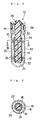
- Fig. 2 is a longitudinal sectional view of the
centrifugal precipitation tube in Fig. 1 showing the state
that the cap section is mounted on the vessel body.
- Fig. 3 is a sectional view taken in the direction of
the arrows along the line III-III in Fig.2.
- Fig. 4 is a partially longitudinal sectional view for
explaining the operation in each process in which centrifugal
separation of a liquid is conducted, and only a lower layer
liquid is extracted using the centrifugal precipitation tube
shown in Fig.1.
- Fig. 5 is a longitudinal sectional view for explaining
a final process of the operation in which centrifugal
separation of the liquid is conducted using the centrifugal
precipitation tube shown in Fig.1 and thereafter only the
lower layer liquid is extracted.
- Fig. 6 shows another embodiment of the first invention
and is a longitudinal sectional view of a centrifugal
precipitation tube showing the state that a cap section is
mounted on a vessel body.
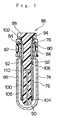
- Fig. 7 shows a further embodiment of the first invention
and is a longitudinal sectional view of a centrifugal
precipitation tube showing the state that a cap section is
mounted on a vessel body.
- Fig. 8 shows a modification of an embodiment of the
first invention and is a partially longitudinal sectional
view of a centrifugal precipitation tube showing the state
that a piston plug of a cap section is fitted and inserted
into an internal tube of a vessel body.
- Fig. 9 shows an embodiment of a second invention and
is a longitudinal sectional view of a centrifugal
precipitation tube.
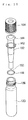
- Fig. 10 is a perspective view showing the state that
the centrifugal precipitation tube shown in Fig. 9 is exploded
into each component.
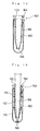
- Fig. 11 is a partial longitudinal sectional view for
explaining an operation wherein a liquid mixture is separated
into an upper layer liquid and a lower layer liquid and only
the lower layer liquid is extracted using the centrifugal
precipitation tube shown in Figs. 9 and 10.
- Fig. 12 is a longitudinal sectional view showing an
example of construction of a conventional centrifugal
precipitation tube in the state that a cap section is mounted
on a vessel body.
- Fig. 13 is a longitudinal sectional view for explaining
a problem in extracting a lower layer liquid using the
conventional centrifugal precipitation tube shown in Fig.
12.
- Fig. 14 is a longitudinal sectional view showing an
example of another construction of a conventional
centrifugal precipitation tube in the state that a cap section
is mounted on a vessel body.
-
Best Mode for carrying Out the Invention
-
Figs. 1 through 3 respectively show an embodiment of
the first invention. Fig. 1 is a front view showing a
centrifugal precipitation tube in the state of being
separated into a vessel body and a cap section with the vessel
body partly broken, Fig. 2 is a longitudinal sectional view
showing the state that the cap section is mounted on the
vessel body, and Fig. 3 is a sectional view taken in the
direction of the arrows along the line III-III in Fig. 2.
-
This centrifugal precipitation tube consists of a
tubular vessel body 10 with its upper surface opened and
a cap section 12 for closing the opening on the upper surface
of the vessel body 10 in a liquid-tight manner. A thread
part 14 is formed on an outer peripheral surface of the upper
end portion of the vessel body 10. An internal tube 16,
diameter of which is smaller than that of the vessel body
10, is inserted into the internal part of the vessel body
10 so as to be coaxial, and the internal tube 16 is fixed
onto the inner wall surface of the vessel body 10 through
upper and lower bridges 18. The internal tube 16 is of a
cylindrical configuration with its upper and lower ends
opened. The upper end face of the internal tube 16 is opened
in the internal part of the vessel body 10 so as to be opposite
to the top opening surface of the vessel body 10, and the
lower end face of the internal tube 16 is opened in the inner
bottom portion of the vessel body 10 so as to be opposite
to the inner bottom face of the vessel body. Further, a
centrifugal separation chamber 20 is formed between the inner
peripheral surface of the vessel body 10 and the outer
peripheral surface of the internal tube 16, and the inside
of the internal tube 16 serves as an extraction chamber 22.
An upper portion and a lower portion of the centrifugal chamber
20 are spatially communicated to an upper opening surface
and a lower opening surface of the internal tube 16
respectively. The vessel body 10 and the internal tube 16
are made of a material such as glass, and in particular the
vessel body 10 is composed of a thick glass so as to be able
to resistant to centrifugal load.
-
The cap section 12 consists of a seal cap 24 and a
rod-shaped piston plug 26, and a clamp 28 integrally connects
them. Formed on the inside surface of the seal cap 24 is
a thread part 30 for screw threading into the thread part
14 at the upper end portion of the vessel body 10. By putting
on and threading the seal cap 24 into the upper end portion
of the vessel body 10, it is possible to close the top opening
of the vessel body 10 in a liquid-tight manner. The piston
plug 26 is formed so that outer diameter thereof is slightly
smaller than inner diameter of the internal tube 16, whereby
the piston plug 26 may be fitted and inserted in the internal
tube 16 of the vessel body 10 as well as pulled out from
the internal tube 16. As shown in Fig.2, the piston plug
26 is formed to have a length allowing the lower end portion
thereof to be inserted in the proximity of the inner bottom
face of the vessel body 10 and to be slightly protruded from
the lower end of the internal tube 16 when screw threading
the seal cap 24 into the upper end portion of the vessel
body 10 and inserting the piston plug 26 into the innermost
area of the internal tube 16. The piston plug 26 is made
of a material such as a fluorine resin.
-
Seal members, for example O rings 32, 34 are
respectively inserted in and fitted on the proximity of the
lower end and on the upper portion of the external peripheral
surface of the piston plug 26. When inserting and fitting
the piston plug 26 in the internal tube 16, each of the O
rings 32, 34 comes in close contact with the inner peripheral
surface of the internal tube 16 in a liquid-tight manner.
Furthermore, the piston plug 26 comes in slidable contact
with the inner peripheral surface of the internal tube 16
so as to be slidable in axial direction. As shown in Fig.2,
the O rings 32, 34 are inserted and fitted in the axial
direction is at positions where the O rings 32, 34 are
respectively stopped in the proximity of the upper and lower
end when screw threading the seal cap 24 into the upper end
portion of the vessel body 10 and inserting the piston plug
26 into the innermost area of the internal tube 16. Therefore,
in the state that the piston plug 26 is inserted into the
innermost area of the internal tube 16, spatial communication
between the lower and upper portions of the centrifugal
separation chamber 20 and the extraction chamber 22 inside
of the internal tube 16 are completely interrupted by means
of the O rings 32, 34, respectively. In addition, instead
of inserting and fitting the O rings 32, 34 on the external
peripheral surface of the piston plug 26, it is also preferable
that the O rings 32, 34 are respectively inserted in and
fixed to the proximity of upper and lower ends of the inner
peripheral surface of the internal tube 16.
-
Further, a slot 36 is formed in the internal part of
the piston plug 26. This slot 36 is opened at lower end face
and at plural points on the external peripheral surface of
the piston plug 26. The slot 36 is opened at a position on
the external peripheral surface of the piston plug 26, and
the opening position is proximate to and slightly below the
position where the O ring 34 is inserted and fitted on the
external peripheral surface of the piston plug 26.
-
Referring now to Figs. 4 (a), (b), (c), (d) and 5,
operation of conducting centrifugal separation of a liquid
and extracting only a lower layer liquid using the centrifugal
precipitation tube constructed as described above will be
hereinafter described.
-
First, in the state that the cap section 12 is removed
from the vessel body 10, a liquid to be separated by means
of centrifugal force is injected into the vessel body 10.
Taking as an example the case that a medicament contained
in a serum is extracted using chloroform, for example, a
serum of 0.5cc, a buffer solution of 0.5cc and chloroform
of 3.5cc are injected into the vessel body 10 in order. Next,
as shown in Fig.2, the piston plug 26 is fitted and inserted
into the internal tube 16 and the seal cap 24 is mounted
on the upper end portion of the vessel body 10. Then, the
seal cap 24 is screw threaded into the upper end portion
of the vessel body 10 and the piston plug 26 is inserted
into the innermost area of the internal tube 16, resulting
in a state that the lower end portion of the piston plug
26 is inserted in the proximity of inner bottom face of the
vessel body 10 and slightly protruded from the lower end
of the internal tube 16. Therefore, internal part of the
vessel body 10 is closed in a liquid-tight manner and a liquid
(chloroform) contained in the extraction chamber 22 inside
of the internal tube 16 is entirely pressed out from the
lower portion of the extraction chamber 22 to the lower portion
of the centrifugal separation chamber 20 between the inner
peripheral surface of the vessel body 10 and the outer
peripheral surface of the internal tube 16 by means of the
piston plug 26. The centrifugal precipitation tube in this
state is subjected to a shaking device and then to a
centrifugal separator. At this time, spatial communication
between the lower and upper portions of the centrifugal
separation chamber 20 and the extraction chamber 22 inside
of the internal tube 16 is completely interrupted by each
of the O rings 32, 34, and the liquid may not flow from the
centrifugal separation chamber 20 into the extraction
chamber 22. Therefore, as showing in the partially
longitudinal sectional view of Fig. 4 (a), the liquid
contained in the centrifugal precipitation tube is separated
into an upper layer liquid (water layer) 38 and a lower layer
liquid (chloroform) 40 in the centrifugal separation chamber
20 due to difference in specific gravity. At this time, note
that injection amount of the mentioned liquid is adjusted
so that lower end of the internal tube 16 is positioned below
a boundary between the upper layer liquid 38 and the lower
layer liquid 40 and lower end portion of the internal tube
16 is immersed in the lower layer liquid 40.
-
After completing the centrifugal separation operation,
the centrifugal precipitation tube is taken out of the
centrifugal separator and the seal cap 24 of the cap section
12 is loosened and removed from the upper end portion of
the vessel body 10. Then, as shown in Fig. 4 (b) , the piston
plug 26 is slowly pulled out from the internal tube 16.
Accordingly, the lower layer liquid 40 in the centrifugal
separation chamber 20 is slowly sucked into the extraction
chamber 22 inside of the internal tube 16. Thus, since the
lower layer liquid 40 in the centrifugal separation chamber
20 is sucked slowly into the extraction chamber 22 by means
of the piston plug 26, it does not take place, in the process
of sucking the lower layer liquid 40 into the extraction
chamber 22, that the boundary between the upper layer liquid
38 and the lower layer liquid 40 in the centrifugal separation
chamber 20 is disturbed and a part of the upper layer liquid
38 is mixed into the lower layer liquid 40 side and flows
into the extraction chamber 22 together with the lower layer
liquid 40.
-
Subsequently when the O ring 34 inserted in and secured
onto the external peripheral surface of the piston plug 26
gets out from the upper edge of the internal tube 16 on the
way of pulled out the piston plug 26 and the opening on the
external peripheral surface of the piston plug 26 of the
slot 36 provided in the internal part of the piston plug
26 passes over the upper end of the internal tube 16, the
upper space of the centrifugal separation chamber 20 and
the space on the side of lower end face of the piston plug
26 are communicated to each other through the slot 36 of
the piston plug 26. As a result, the same air pressure is
applied to the liquid surface of the lower layer liquid 40
in the extraction chamber 22 and to that of the upper layer
liquid 38 in the centrifugal separation chamber 20
respectively. Accordingly, even though the piston plug 26
is pulled out further as shown in Fig. 4 (c), the lower layer
liquid 40 in the extraction chamber 22 is prevented from
being sucked up by the piston plug 26. Therefore, it does
not take place that not only lower layer liquid 40 but also
upper layer liquid 38 flows into the extraction chamber 22
and a part of the upper layer liquid 38 is mixed into the
lower layer liquid 40 in the extraction chamber 22.
-
When the piston plug 26 has been completely pulled out
from the internal tube 16, as shown in Fig. 4 (d), liquid
surface of the upper layer liquid 38 in the centrifugal
separation chamber 20 becomes generally coincident with that
of the lower layer liquid 40 in the extraction chamber 22.
More exactly, the liquid surface of the lower layer liquid
(chloroform) 40 in the extraction chamber 22 becomes slightly
below the liquid surface of the upper layer liquid (water
layer) 38 due to difference in specific gravity. At this
time, injection amount of the mentioned chloroform has been
adjusted so that only the lower layer liquid 40 may remain
in the extraction chamber 22. In order that lower layer
liquid 40 remaining in the extraction chamber 22 may be
extracted by means of an automatic dispensing apparatus (not
shown), a centrifugal precipitation tube is fixed, a
dispensing nozzle 42 is lowered by means of a nozzle drive
mechanism (not shown), and the lower end portion of a
disposable chip (throw-away chip) 44 forming the lower end
portion of the dispensing nozzle 42 is deeply inserted into
the innermost area of the internal tube 16 through the top
opening of the vessel body 10. Then, after inserting the
lower end of the disposable chip 44 into the lower layer
liquid 40, the lower layer liquid 40 is sucked into the
disposable chip 44 through the lower end opening of the
disposable chip 44 by driving a syringe (not shown).
Alternatively, in the case of manual operation, lower end
portion of a pipette (not shown) is likewise inserted deeply
into the internal tube 16 through the top opening of the
vessel body 10, and after inserting the lower end of the
pipette into the lower layer liquid 40, the lower layer liquid
40 is sucked into the pipette.
-
Now another preferred embodiment of the first invention
is hereinafter described with reference to Fig. 6 that is
a longitudinal sectional view of a centrifugal precipitation
tube showing a state that a cap section is mounted on a vessel
body.
-
In the internal part of a vessel body 46, an internal
tube 48 is inserted from the proximity of upper end opening
to the proximity of inner bottom face of the vessel body
46. Then, an outer peripheral surface of upper end portion
of the internal tube 48 is welded on the inner peripheral
surface of a mouth portion of the vessel body 46 on which
a seal cap 52 of a cap section 50 is mounted, and the internal
tube 48 is integrally secured to the vessel body 46.
Accordingly, upper portion of a centrifugal separation
chamber 54 formed between the inner peripheral surface of
the vessel body 46 and outer peripheral surface of the internal
tube 48 is spatially closed. On the other hand, in the
internal tube 48, plural communication apertures 56 are
opened at positions corresponding to the upper portion of
the centrifugal separation chamber 54, whereby the upper
portion of the centrifugal chamber 54 and an extraction
chamber 58 inside of the internal tube 48 are communicated
to each other through those communication apertures 56.
-
A rod-shaped piston plug 62 integrally connected to the
seal cap 52 of the cap section 50 by means of a clamp 60
is inserted and fitted over the entire length of the internal
tube 48. The piston plug 62 is formed so as to have a length
within which lower end portion of the piston plug 62 is
inserted in the proximity of inner bottom face of the vessel
body 46 and slightly protruded from lower end of the internal
tube 48 when inserting the piston plug 62 into the innermost
area of the internal tube 48. Further on external peripheral
surface of the piston plug 62, O rings 64, 66 are respectively
inserted and secured in the proximity of lower end of the
piston plug 62 and at a position of closing the communication
aperture 56 of the internal tube 48 in a liquid-tight manner
when the piston plug 62 being inserted into the innermost
area of the internal tube 48. Therefore, in the same manner
as the centrifugal precipitation tube shown in Figs. 1 through
3, in the state of the piston plug 62 being inserted into
the innermost area of the internal tube 48, the spatial
communication between the lower and upper portions of the
centrifugal separation chamber 54 and the extraction chamber
58 inside of the internal tube 48 is completely interrupted
respectively.
-
Formed in the internal part of the piston plug 62 are
slots 68 which are opened at the lower end face as well as
at plural points on the external surface of the piston plug
62. Then, the external peripheral surface of the piston plug
62 between both of positions at which upper and lower O rings
64, 66 are inserted and secured, is reduced in diameter to
form a concave surface part 70, and the slot 68 are formed
so as to communicate to the concave surface part 70. It is
also preferable that a plurality of longitudinal grooves
communicating to the slot 68 is provided on the external
peripheral surface of the piston plug 62 instead of forming
a part of the external peripheral surface of the piston plug
62 to reduce the diameter thereby forming the concave surface
part 70. Reference numeral 72 shows a packing.
-
Fig. 7 shows a further embodiment of the first invention,
and is a longitudinal sectional view of a centrifugal
separation tube showing the state that a cap section is mounted
on a vessel body.
-
This centrifugal precipitation tube is constructed so
that an internal tube 76 may be removably inserted in and
fixed to the internal part of the vessel body 74. That is,
the internal tube 76 is formed to have an outer diameter
capable of being in close contact with the mouth portion
of the vessel body 74. The internal tube 76 is provided with
an annular protrusion 78 in the proximity of the upper end
thereof. The internal tube 76 is inserted into the vessel
body 74, the annular protrusion 78 is brought into close
contact with the upper end face of the vessel body 74 by
interposition of a packing 80, and subsequently a cylindrical
fixing member 82, on the inner surface of which a thread
part 84 is formed and which fits onto the upper end portion
of the internal tube 76, is mounted onto the upper end portion
of the vessel body 74 and screwed in a thread part 86 of
the vessel body 74, thereby the internal tube 74 being secured
to the vessel body 74. In order to separate the internal
tube 76 from the vessel body 74, the fixing member 82 is
removed from the upper end portion of the vessel body 74
and then the internal tube 76 is pulled out from the internal
part of the vessel body 74.
-
In the same manner as the centrifugal precipitation
tube shown in Fig. 6, opened in the internal tube 76 are
plural communication apertures 92 for communicating the
upper portion of a centrifugal separation chamber 88 formed
between the inner peripheral surface of the vessel body 74
and outer peripheral surface of the internal tube 76 to an
extraction chamber 90 inside of the internal tube 76.
Furthermore, athread part 94 is formed on the inner peripheral
surface of the upper end portion of the internal tube 76.
-
In the centrifugal precipitation tube shown in Fig.
7, a seal cap 98 and a rod-shaped piston plug 100 forming
a cap section 96 are integrally molded of a fluorine resin
or the like. On the external peripheral surface of the upper
end portion of the piston plug 100 connecting to the seal
cap 98, a thread part 102 threading to the thread part 94
on inner peripheral surface of the upper end portion of the
internal tube 76 is formed. Then the piston plug 100 is fitted
and inserted into the internal tube 76 and the upper end
portion of the piston plug 100 is screw threaded into the
upper end portion of the internal tube 76, whereby opening
surface of the upper end of the internal tube 76 can be closed
in a liquid-tight manner by means of the seal cap 98. Further,
in the same manner as the centrifugal precipitation tube
shown in Fig.6, on the external peripheral surface of the
piston plug 100, two O rings 104, 106 are inserted and secured.
When inserting the piston plug 100 into the innermost area
of the internal tube 76, spatial communication between the
lower and upper portions of the centrifugal separation
chamber 88 and the extraction chamber 90 inside of the internal
tube 76 becomes completely interrupted by means of each of
O rings 104, 106. Further in the internal part of the piston
plug 100, a slot 108 opened at lower end face and at a plurality
of points on the external peripheral surface of the piston
plug 100 are formed. On the external peripheral surface of
the piston plug 100 between both of positions at which the
upper and lower O rings 104, 106 are inserted and secured,
a concave surface part 110 is formed.
-
Extraction operation of the lower layer liquid using
the centrifugal precipitation tube shown respectively in
Figs. 6 and 7 is conducted in the same manner as the case
using a centrifugal precipitation tube shown in Figs. 1
through 3. However, when extracting a lower layer liquid
from a centrifugal precipitation tube after completion of
the centrifugal separation operation, in the centrifugal
precipitation tube shown in Figs. 6 and 7, during the step
of pulling out the piston plug 62 or 100, the O ring 66 or
106 inserted and secured on the external surface of the piston
plug 62 or 100 are upwardly displaced from the position of
the communication aperture 56 or 92 in the internal tube
48 or 76. Further, the upper end portion of the concave
surface part 70 or 110 formed on the external peripheral
surface of the piston plug 62 or 100 passes over the
communication aperture 56 or 92 in the internal tube 48 or
76, whereby upper portion of the centrifugal separation
chamber 54 or 88 and space on the side of lower end face
of the piston plug 62 or 100 in the extraction chamber 58,
90 are communicated to each other through the communication
aperture 68 or 108 of the internal tube 48 or 76, through
the clearance between the concave surface part 70 or 110
on the external surface of piston plug 62 or 100 and inner
peripheral surface of internal tube 48 or 76 and through
the slot 68 or 108 of the piston plug 62 or 100. Accordingly,
the same air pressure is applied onto the liquid surface
of lower layer liquid in the extraction chamber 58 or 90
and the liquid surface of upper layer liquid in the centrifugal
separation chamber 54 or 88 respectively.
-
In each of the foregoing embodiments, in order that the
upper portion of the centrifugal separation chamber 20, 54
or 88 and the space on the lower end face side of the piston
plug 26, 62 or 100 may be communicated to each other during
the process of pulling out the piston plug 26, 62 or 100
from the state of being inserted into the innermost area
of the internal tube 16, 48 or 76, the slot 36, 68 or 108
is formed in the internal part of the piston plug 26, 62
or 100. However, communication means to perform such a
function is not limited to the slot 36, 68 or 108 formed
in the internal part of the piston plug 26, 62 or 100. An
example of communication means is constructed as described
hereinafter with reference to Fig. 8. Inner diameter of an
internal tube 114 inserted and fixed in the internal part
of a vessel body 112 is formed so that upper side portion
thereof is larger than the lower end portion. Further, when
inserting a piston plug 120 into the innermost area of the
internal tube 114, an O ring 122 inserted and secured in
the proximity of the lower end portion of the external
peripheral surface of the piston plug 120 is brought into
close contact with the inner peripheral surface of a thickened
part (smaller inner-diameter portion) of the internal tube
114, and another O ring 124 inserted and secured to the upper
portion of external peripheral surface of the piston plug
120 is brought into close contact with the inner peripheral
surface of a thinned part (larger inner-diameter portion)
118. By employing such construction, in the a state of
inserting the piston plug 120 into the innermost area of
the internal tube 114, spatial communication between the
lower and upper portions of a centrifugal separation chamber
126 located between the inner peripheral surface of the vessel
body 112 and outer peripheral surface of the internal tube
114 and an extraction chamber 128 inside of the internal
tube 114 is completely interrupted by each of the O rings
122, 124. On the other hand, during the process of pulling
out the piston plug 120 from the state of being inserted
into the innermost area of the internal tube 114, on and
after the O ring 122 inserted and secured in the proximity
of the lower end of external peripheral surface of the piston
plug 120 gets out from the thickened part 116 of the internal
tube 114, upper space of the centrifugal separation chamber
126 and space on the lower end face side of the piston plug
120 in the extraction chamber 128 are communicated to each
other through a clearance between the inner peripheral
surface of the thinned part of the internal tube 114 and
external peripheral surface of the piston plug 120.
-
Figs. 9 and 10 show an embodiment according to the second
invention. Fig. 9 is a longitudinal sectional view of a
centrifugal precipitation tube, and Fig. 10 is a perspective
view showing the centrifugal precipitation tube in the state
of being exploded into several components.
-
This centrifugal precipitation tube consists of a
tubular-shaped vessel body 130 top of which is opened and
with a bottom, an internal tube 132 to be inserted in the
internal part of the vessel body 130, and a cap 134 to be
mounted on an upper end portion of the vessel body 130 and
the like. A thread part 136 is formed on the outer peripheral
surface of the upper end portion of the vessel body 130,
and a thread part 138 for screw threading with the thread
part 136 of the vessel body 130 is formed on inner peripheral
surface of the cap 134. Further, a through hole 140 is formed
at the central portion of the upper surface of the cap 134.
The cap 134 and the internal tube 132 are integrally connected
together by means of a connection ring 142 interposed on
the inner side of the cap 134.
-
The internal tube 132 has an outer diameter smaller than
inner diameter of the vessel body 130 and is formed into
a tubular shape with its lower part tapered gradually. A
flange part 144 is formed at the upper end portion of the
internal tube 132. This flange part 144 comes engaged and
in close contacts with the upper edge of the vessel body
130 properly by interposing, for example, an O ring 146 when
inserting the internal tube 132 into the internal part of
the vessel body 130. As far as the flange part 144 can come
in close contact with the upper edge of the vessel body 130
properly, such O ring 146 is not always required to be
interposed. The internal tube 132 is inserted into the
internal part of the vessel body 130, whereby a centrifugal
separation chamber 148 is formed between the inner peripheral
surface of the vessel body 130 and the outer peripheral surface
of the internal tube 132. Moreover, in the state that the
internal tube 132 is inserted into the internal part of the
vessel body 130, there is an extremely slight clearance
capable of performing ventilation between the outer
peripheral surface of the upper portion of the internal tube
132 and the inner peripheral surface of the upper portion
of the vessel body 130. The internal tube 132 has a length
within which lower end thereof is positioned in the proximity
of inner bottom face of the vessel body 130 when inserting
the internal tube 132 into the innermost area of the vessel
body 130.
-
At the lower end portion of the internal tube 132, a
closure plug 150 is upwardly inserted into the lower end
opening of the internal tube 132, and the lower end opening
of the internal tube 132 is closed in a liquid-tight manner.
The closure plug 150 is formed so as to be easily come off
by a downward pressure force, i.e., a downwardly pressing
force given by the lower end of a dispensing nozzle, pipette
or the like. This closure plug 150 is configured in such
a manner as to have a conical or pyramidal lower surface
side.
-
Now operation for extracting only a lower layer liquid
by centrifugal separation of liquid using the centrifugal
precipitation tube of above construction is hereinafter
described referring to Fig. 11.
-
First in the state that the cap 134 is removed from
the vessel body 130 and the internal tube 132 is pulled out,
a liquid mixture to be separated by means of centrifugal
force is injected into the vessel body 130. Taking as an
example the case that a medicament contained in a serum is
extracted using chloroform, for example, a serum of 0.5cc,
a buffer solution of 0.5cc and chloroform of 3.5cc are injected
into the vessel body 130 in order. Next, the internal tube
132 is deeply put in the internal part of the vessel body
130 and inserted into liquid, and then the cap 134 is mounted
on the upper end portion of the vessel body 130 and screw
threaded as far as it goes. Accordingly, the flange part
144 of the internal tube 132 is pressed onto the top edge
of the vessel body 130 with interposition of the O ring 146
by means of the peripheral edge portion of a through hole
140 opened on the upper surface of the cap 134. Then, the
flange part 144 of the internal tube 132 and the top edge
of the vessel body 130 are brought into close contact with
each other. Thus, a centrifugal separation chamber 148
between the inner peripheral surface of the vessel body 130
and outer peripheral surface of the internal tube 132 is
sealed in an air-tight manner as well as in a liquid-tight
manner. A centrifugal precipitation tube in this state is
subjected to a shaking device, a medicament contained in
a serum is transferred into chloroform, and then the
centrifugal precipitation tube is set in and subjected to
a centrifugal separator. Consequently, as shown in Fig. 11
(a), a liquid accommodated in the centrifugal separation
chamber 148 is separated into an upper layer liquid (water
layer) 152 and a lower layer liquid (chloroform) 154 due
to difference in specific gravity. At this time, as shown
in Fig.11 (a), the lower end of the internal tube 132 is
positioned in the proximity of inner bottom face of the vessel
body 130. Therefore, lower end of the internal tube 132 is
positioned below a boundary 156 between the upper layer liquid
152 and the lower layer liquid 154. Thus, a portion proximate
to the lower end of the internal tube 132 is in the state
of being inserted into the lower layer liquid 154.
-
After completing the operation of centrifugal
separation, the centrifugal precipitation tube is taken out
of the centrifugal separator and only the lower layer liquid
is extracted from the centrifugal precipitation tube by means
of an automatic dispensing apparatus (not shown) . In order
to conduct this, first the cap 134 mounted on the upper end
portion of the vessel body 130 is twisted and released.
Accordingly, the state of the flange part 144 of the internal
tube 132 being in close contact with the top edge of the
vessel body 130 is released. Thus, the centrifugal
separation chamber 148 are communicated to the outside air
through a clearance between the inner peripheral surface
of the upper portion of the vessel body 130 and the outer
peripheral surface of the upper portion of the internal tube
132 and through a clearance between the flange part 144 of
the internal tube 132 and the top edge of the vessel body
130. Then, the centrifugal precipitation tube in this state
is fixed to a mounting portion of the automatic dispensing
apparatus. Subsequently, a dispensing nozzle is lowered by
means of a nozzle drive mechanism. Then, as shown in Fig.
9, a disposable chip (hereinafter referred to as
"dispochip") 158 forming a lower end portion of the dispensing
nozzle is deeply inserted into the internal part of the
internal tube 132 through the through hole 140 in the cap
134 of the centrifugal precipitation tube. Next, as shown
in Fig. 11 (a), the closure plug 150 at the lower end of
the internal tube 132 is downwardly pressed by means of the
lower end of the dispochip 158. Accordingly, as shown in
Fig. 11 (b), the closure plug 150 is disengaged from the
lower end opening of the internal tube 132, and the lower
end of the dispochip is inserted into the lower layer liquid
154. At this time, since the centrifugal separation chamber
148 is communicated to the outside air as described above,
it does not occur that the liquid flushes into the internal
tube 132 due to gas pressure of the vapor phase portion,
even though the closure plug 150 is disengaged from the lower
end opening of the internal tube 132.
-
The closure plug 150 having been disengaged from the
lower end opening of the internal tube 132 sinks vertically
right under the lower end opening of the internal tube 132.
The closure plug 150 having reached to the inner bottom face
of the vessel body 130 falls down in any one of forward,
backward, leftward or rightward directions because the lower
surface side of the closure plug 150 is formed conical.
Therefore, as shown in Fig. 11 (c), even though the lower
end of the dispochip 158 is inserted in the proximity of
the inner bottom face of the vessel body 130, the closure
plug 150 is pressed away by the lower end of the dispochip
158 or a part of the lower end face of the dispochip 158
comes in contact with the closure plug 150. As a result,
it does not occur that the lower end face of the dispochip
158 comes in contact with the closure plug 150 and the entire
of the lower end opening of the dispochip 158 is closed by
the closure plug 150.
-
Since the lower end of the dispochip 158 is inserted
into the lower layer liquid 154, the lower layer liquid 154
is sucked into the dispochip 158 through the lower end opening
of the dispochip 158 by driving a syringe connected to the
dispensing nozzle. At this time, as described above, since
the lower end opening of the dispochip 158 is not closed
by the closure plug 150, the lower layer liquid 154 is sucked
without fail into the dispochip 158. In addition, at this
time, since the lower end of the dispochip 158 is positioned
further below the boundary between the upper layer liquid
152 and the lower layer liquid 154, there is no such worry
that a part of the upper layer liquid 152 is mixed into the
lower layer liquid 154 and a contamination takes place.
-
Further, in the foregoing embodiments, the internal
tube 132 and the cap 134 are separated. It is, however, also
preferable that the internal tube and the cap is integrally
formed or molded as shown in Fig. 12. Further, in the above
description referring to Fig. 11, only the lower layer liquid
is extracted from the centrifugal precipitation tube by means
of the automatic dispensing apparatus. It is, however, also
possible that only the lower layer liquid is extracted from
the centrifugal precipitation tube by manual operation using
a hole pipette or the like, as a matter of course.
-
Furthermore, in the foregoing embodiments, the lower
surface side of the closure plug 150 is formed into a conical
or pyramidal shape. However, it is also preferable that the
lower surface side of a closure plug may be formed into any
other shape, as far as the closure plug comes off from the
lower end portion of the internal tube and falls down in
any one of forward, rearward, leftward and rightward
directions from the coming off position upon reaching the
inner bottom face of the vessel body. In this sense, it is
preferable that a rod-shaped protrusion is provided at the
central portion of the lower surface of a closure plug.
Industrial Applicability
-
The centrifugal precipitation tube according to the
present invention is used, for example, in the case that
any medicament contained in a serum is extracted in the form
of solvent extraction by an automatic extraction apparatus,
or in the case that a medicament contained in a serum is
extracted in the form of solvent extraction and concentration
of the medicament is automatically measured by an automatic
concentration measurement apparatus, when a liquid mixture
of serum to which a solvent such as chloroform, after being
shaken, is separated into a water phase and a solvent phase
utilizing a difference in specific gravity by a centrifugal
separator. When using this centrifugal precipitation tube,
it becomes possible that only a lower layer liquid is exactly
extracted without contamination involving an upper layer
liquid.