EP1204256B1 - Adaptive modulation communication system - Google Patents
Adaptive modulation communication system Download PDFInfo
- Publication number
- EP1204256B1 EP1204256B1 EP01941207A EP01941207A EP1204256B1 EP 1204256 B1 EP1204256 B1 EP 1204256B1 EP 01941207 A EP01941207 A EP 01941207A EP 01941207 A EP01941207 A EP 01941207A EP 1204256 B1 EP1204256 B1 EP 1204256B1
- Authority
- EP
- European Patent Office
- Prior art keywords
- modulation
- bits
- signal
- data
- bit
- Prior art date
- Legal status (The legal status is an assumption and is not a legal conclusion. Google has not performed a legal analysis and makes no representation as to the accuracy of the status listed.)
- Expired - Lifetime
Links
Images


Classifications
-
- H—ELECTRICITY
- H04—ELECTRIC COMMUNICATION TECHNIQUE
- H04L—TRANSMISSION OF DIGITAL INFORMATION, e.g. TELEGRAPHIC COMMUNICATION
- H04L27/00—Modulated-carrier systems
-
- H—ELECTRICITY
- H04—ELECTRIC COMMUNICATION TECHNIQUE
- H04L—TRANSMISSION OF DIGITAL INFORMATION, e.g. TELEGRAPHIC COMMUNICATION
- H04L27/00—Modulated-carrier systems
- H04L27/32—Carrier systems characterised by combinations of two or more of the types covered by groups H04L27/02, H04L27/10, H04L27/18 or H04L27/26
- H04L27/34—Amplitude- and phase-modulated carrier systems, e.g. quadrature-amplitude modulated carrier systems
- H04L27/3488—Multiresolution systems
-
- H—ELECTRICITY
- H04—ELECTRIC COMMUNICATION TECHNIQUE
- H04L—TRANSMISSION OF DIGITAL INFORMATION, e.g. TELEGRAPHIC COMMUNICATION
- H04L1/00—Arrangements for detecting or preventing errors in the information received
- H04L1/12—Arrangements for detecting or preventing errors in the information received by using return channel
- H04L1/16—Arrangements for detecting or preventing errors in the information received by using return channel in which the return channel carries supervisory signals, e.g. repetition request signals
- H04L1/18—Automatic repetition systems, e.g. Van Duuren systems
- H04L1/1867—Arrangements specially adapted for the transmitter end
-
- H—ELECTRICITY
- H04—ELECTRIC COMMUNICATION TECHNIQUE
- H04L—TRANSMISSION OF DIGITAL INFORMATION, e.g. TELEGRAPHIC COMMUNICATION
- H04L27/00—Modulated-carrier systems
- H04L27/0008—Modulated-carrier systems arrangements for allowing a transmitter or receiver to use more than one type of modulation
-
- H—ELECTRICITY
- H04—ELECTRIC COMMUNICATION TECHNIQUE
- H04L—TRANSMISSION OF DIGITAL INFORMATION, e.g. TELEGRAPHIC COMMUNICATION
- H04L27/00—Modulated-carrier systems
- H04L27/18—Phase-modulated carrier systems, i.e. using phase-shift keying
- H04L27/183—Multiresolution systems
-
- H—ELECTRICITY
- H04—ELECTRIC COMMUNICATION TECHNIQUE
- H04L—TRANSMISSION OF DIGITAL INFORMATION, e.g. TELEGRAPHIC COMMUNICATION
- H04L1/00—Arrangements for detecting or preventing errors in the information received
- H04L1/004—Arrangements for detecting or preventing errors in the information received by using forward error control
- H04L1/0056—Systems characterized by the type of code used
- H04L1/0057—Block codes
- H04L1/0058—Block-coded modulation
Definitions
- the present invention relates to a new adaptive modulation communication system used in a digital radio communication system.
- One of the techniques is an adaptive modulation communication system where on a transmitting side a modulation scheme is adaptively varied to perform efficient data transmission.
- a conventional adaptive modulation communication system will be described with reference to FIG.1 .
- CQES(channel quality estimating section) 1 in a transmitting-side apparatus estimates a channel quality using a received signal.
- the estimated channel quality information is output to MLDS (modulation level determining section) 2.
- MLDS 2 determines a modulation level based on the channel quality information. For example, when the channel quality is good, MLDS 2 increases the modulation level, while decreasing the modulation level when the channel quality is poor.
- a broadcast signal indicative of modulation level is output to buffer 5, while being output to modulation section 6-2.
- Transmit data is output to EDBAS(error detecting bit adding section) 3, where an error detecting bit is added.
- the transmit data with the error detecting bit added thereto is output to ECCS(error correcting coding section) 4 to undergo error correcting coding.
- the transmit data subjected to the error correcting coding is output to buffer 5 to be stored therein.
- the transmit data is output to modulation section 6-1 for each modulation unit of the determined modulation scheme.
- Modulation section 6-2 modulates the modulation level broadcast signal to output to adder 7.
- Modulation section 6-1 modulates the transmit data output from buffer 5 to output to adder 7.
- Adder 7 multiplexes the modulation level broadcast signal and the transmit data.
- the multiplexed signal is output to radio transmission section 8, is subjected to the predetermined radio transmission processing (for example, D/A conversion and upconverting) in radio transmission section 8, and the resultant radio signal is transmitted to a receiving-side apparatus (communication party) via antenna 9.
- the predetermined radio transmission processing for example, D/A conversion and upconverting
- the signal transmitted from the transmitting-side apparatus is received in radio reception section 13 via antenna 12 in the receiving-side apparatus.
- Radio reception section 13 performs the predetermined radio reception processing (for example, downconverting and A/D conversion) on the received signal.
- the signal subjected to the radio reception processing is demultiplexed to the modulation level broadcast signal and data, and the signal and data is output to demodulation section 14. Specifically, the data is output to demodulation section 14-1, and the modulation level broadcast signal is output to demodulation section 14-2.
- Demodulation section 14-2 demodulates the modulation level broadcast signal to obtain information on the modulation scheme (modulation level) on the transmitting-side apparatus. The information on the modulation scheme is output to demodulation section 14-1.
- demodulation section 14-1 demodulates the data.
- the demodulated data is output to error correcting decoding section 15 to undergo error correcting decoding.
- the error-correcting-decoded data is output to error detecting section 16 to undergo error detection.
- An output of error detecting section 16 is received data. Further, a detection result (a result when an error is detected) in error detecting section 16 is output to modulation section 17 as a repeat request signal.
- Modulation section 17 modulates the repeat request signal as well as the transmit data.
- the modulated signal is output to radio transmission section 18.
- Radio transmission section 18 performs the predetermined radio transmission processing on the modulated signal.
- the signal subjected to the radio transmission processing is transmitted to the transmitting-side apparatus (communication party) via antenna 12.
- the signal including the repeat request signal is received in radio reception section 10 via antenna 9.
- Radio reception section 10 performs the predetermined radio reception processing on the received signal.
- the signal subjected to the radio reception processing is output to demodulation section 11.
- Demodulation section 11 demodulates the data and the repeat request signal.
- the data becomes received data, and the repeat request signal is output to buffer 5.
- buffer 5 outputs data targeted for the repeat to modulation section 6-1.
- the information on the modulation scheme (modulation level or the like) is multiplexed on a transmit signal in transmitting signals.
- the receiving side it is possible to perform demodulation according to the information on the modulation scheme even when the modulation scheme is varied adaptively.
- the receiving-side apparatus is not capable of demodulating data unless the transmitting-side notifies the receiving-side apparatus of the information on the modulation scheme (modulation level broadcast signal). Accordingly, it is necessary to transmit the information of the modulation level broadcast signal with greatly high quality. Further, demodulating data is started only after the modulation level broadcast signal is demodulated, and furthermore, an erroneous modulation level broadcast signal disables the reception even when the data quality is high.
- a method is proposed in which a receiving-side apparatus determines a modulation scheme used in a transmitting-side apparatus using a signal variance, but since the detection accuracy is low in this method, is not very practical.
- EP 0 531 046 A2 describes a communication system, in which the receiver is provided with plural demodulators configured with different modulation schemes. Upon receiving a signal all demodulators individually try to demodulate a received signal (modulation symbol) using a respective modulation scheme specific to the demodulators, respectively. Thereupon, error values are calculated for each demodulator and the demodulator with the lowest probability of error is selected to output the demodulated data.
- the inventor of the present invention noted the state of mapping per bit basis in a signal space diagram in M-ary modulation, found out demodulation is allowed independently of a modulation scheme used in a transmitting-side apparatus by determining demodulation patterns for each predetermined unit, and carried out the present invention.
- a transmitting-side apparatus sets different error detecting units corresponding to bit position, and transmits data subjected to error detecting processing on a different error detecting unit basis corresponding to bit position, and a receiving-side apparatus performs demodulation independently using different demodulation patterns for each error detecting unit to obtain received data.
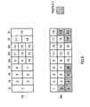
- FIG.2 is a block diagram illustrating a configuration of an adaptive modulation communication system according to the embodiments of the present invention.
- CQES(channel quality estimating section) 101 in a transmitting-side apparatus estimates a channel quality using a received signal.
- the estimated channel quality information is output to MLDS(modulation level determining section) 102.
- MLDS 102 determines a modulation level based on the channel quality information. For example, when the channel quality is good, MLDS 102 increases the modulation level, while decreasing the modulation level when the channel quality is poor.
- the information on the modulation level is output to buffer 105, while being output to modulation section 106.
- Transmit data is output to EDBAS(error detecting bit adding section) 103, where an error detecting bit is added for each error detection unit.
- the transmit data with the error detecting bit added thereto is output to ECCS(error correcting coding section) 104 to undergo error correcting coding.
- the transmit data subjected to the error correcting coding is output to buffer 105 to be stored therein.
- the transmit data is output to modulation section 106 for each modulation unit of the determined modulation scheme.
- Modulation section 106 modulates the transmit data, and outputs the modulated signal to radio transmission section 107.
- the transmit signal is subjected to the predetermined radio transmission processing (for example, D/A conversion and upconverting) in radio transmission section 107, and the resultant radio signal is transmitted to a receiving-side apparatus (communication party) via antenna 108.
- predetermined radio transmission processing for example, D/A conversion and upconverting
- Radio reception section 112 performs the predetermined radio reception processing (for example, downconverting and A/D conversion) on the received signal.
- the signal subjected to the radio reception processing is output to demodulation sections 113-1 to 113-n for each predetermined unit
- demodulation sections 113-1 to 113-n demodulate signals for each predetermined unit according to respective demodulation patterns.
- the demodulated data is output to ECDS(error correcting decoding sections) 114-1 to 114-n respectively to undergo error correcting decoding. Then, the error-correcting-decoded data is output to error detecting sections 115-1 to 115-n respectively to undergo error detection. Outputs of error detecting sections 115-1 to 115-n are received data. Further, a detection result (a result when an error is detected) in each of error detecting sections 115-1 to 115-n is output to modulation section 116 as a repeat request signal.
- Modulation section 116 modulates the repeat request signal as well as the transmit data.
- the modulated signal is output to radio transmission section 117.
- Radio transmission section 117 performs the predetermined radio transmission processing on the modulated signal.
- the signal subjected to the radio transmission processing is transmitted to the transmitting-side apparatus (communication party) via antenna 111.
- the signal including the repeat request signal is received in radio reception section 109 via antenna 108.
- Radio reception section 109 performs the predetermined radio reception processing on the received signal.
- the signal subjected to the radio reception processing is output to demodulation section 110.
- Demodulation section 110 demodulates the data and repeat request signal.
- the data becomes received data, and the repeat request signal is output to buffer 105.
- buffer 105 outputs data targeted for the repeat to modulation section 106.
- the transmitting-side apparatus divides transmit data into predetermined units, and adds an error detecting bit such as CRC (Cyclic Redundancy Check) for each unit in EDBAS 103.
- CRC Cyclic Redundancy Check
- the number of units of a predetermined unit is made different corresponding to modulation scheme in performing M-ary modulation.
- one unit is set as a transmit unit in a slot
- QPSK two units are set as a transmit unit in a slot
- 8QAM three units are set as a transmit unit in a slot
- 16QAM four units are set as a transmit unit in a slot
- 32QAM five units are set as a transmit unit in a slot
- 64QAM six units are set as a transmit unit in a slot
- the transmit unit is concurrently transmitted.
- Each unit is capable of undergoing error detection independently. In this way, it is possible to perform the error correction and error detection only once, and a difference in transmit rate corresponding to modulation scheme can be represented by the number of units transmitted concurrently, thereby facilitating resource allocation in performing M-ary modulation.
- a signal bit For example, 64QAM is set for six units in a slot, and one bit may be set as one unit, or two or more bits are set as one unit. Specifically, it may be possible to with two bits set as one unit, set a unit as a transmit unit in QPSK, set two units as a transmit unit in 16QAM, and set three units as a transmit unit in 64QAM, to transmit concurrently. In this way, it is possible to readily perform resource allocation in performing M-ary modulation, using less candidates.
- the transmit data with the error detecting bit added as described above is subjected to the predetermined error correcting coding in ECCS 104, and the coded signal is output to buffer 105.
- To buffer 105 is input the information on the modulation level determined from the channel quality estimated based on the received signal. Based on the information on the modulation level, buffer 105 outputs the transmit data for each transmit unit of the determined modulation scheme to modulation section 106.
- the transmit data is modulated in modulation section 106, the modulated signal is subjected to the predetermined radio transmission processing in radio transmission section 107, the radio signal is transmitted to the receiving-side apparatus (communication party) from antenna 108.
- data is output to demodulation sections 113-1 to 113-n for each unit set in the transmitting-side apparatus, and demodulation sections 113-1 to 113-n demodulate the data according to respective demodulation patterns.
- the transmitting-side apparatus determines 64QAM as the modulation scheme, sets one unit at one bit, and transmits six units as a transmit unit, in other words, that the apparatus adds an error detecting bit for each error detection unit and transmits six bits as a transmit unit.
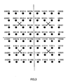
- FIG.3 is a diagram to explain a signal space diagram of 64QAM.
- FIG.4 is a diagram to explain a demodulation method for 64QAM in the adaptive modulation communication system of the present invention.
- S0 With respect to the most significant bit (bit at the leftmost as viewed in the figure) S0, such bits are "0" at the left side of the vertical axis (Q-axis), while being “1” at the right side of the vertical axis.
- S0 is capable of being demodulated according to a demodulation pattern comprised of a portion 301 at the left side of the vertical axis and a portion 302 at the right side of the vertical axis.
- S1 is capable of being demodulated according to a demodulation pattern comprised of a portion 303 at the upper side of the horizontal axis and a portion 304 at the lower side of the horizontal axis.
- a demodulation pattern comprised of a portion 303 at the upper side of the horizontal axis and a portion 304 at the lower side of the horizontal axis.
- S2 is capable of being demodulated according to a demodulation pattern comprised of portions 305 at the sides, opposed to the vertical axis, of axes spaced equal horizontal distances apart from the vertical axis and a portion 306 at the center including the vertical axis.
- S3 With respect to a fourth significant bit (bit at the fourth left as viewed in the figure) S3, such bits are "0" at the sides, opposed to the horizontal axis (I-axis), of axes (existing at the midpoint of signal points in the vertical direction) spaced equal vertical distances apart from the horizontal axis, while being "1" at the center portion including the horizontal axis. Accordingly, as shown in FIG.4D , S3 is capable of being demodulated according to a demodulation pattern comprised of portions 307 at the sides, opposed to the horizontal axis, of axes spaced equal vertical distances apart from the horizontal axis and a portion 308 at the center including the horizontal axis.
- bits at the fifth left as viewed in the figure are "0" at a first portion, including the vertical axis (Q-axis), between axes spaced equal horizontal distances apart from the vertical axis, are "1" at second portions, with the same horizontal width as the first portion, at opposite sides of the first portion, and are "0" at third portions outside the second portions.
- S4 is capable of being demodulated according to a demodulation pattern comprised of the first portion 309, including the vertical axis, between axes spaced equal horizontal distances apart from the vertical axis, the second portions 310, with the same horizontal width as the first portion 309, at opposite sides of the first portion, and the third portions 309 outside the second portions 310.
- bits at the sixth left as viewed in the figure are "0" at a first portion, including the horizontal axis (I-axis), between axes spaced equal vertical distances apart from the horizontal axis, are "1" at second portions , with the same vertical width as the first portion, at opposite sides of the first portion, and are "0" at third portions outside the second portions.
- S5 is capable of being demodulated according to a demodulation pattern comprised of the first portion 311, including the horizontal axis, between axes spaced equal vertical distances apart from the horizontal axis, the second portions 312, with the same vertical width as the first portion 311, at opposite sides of the first portion, and the third portions 311 outside the second portions 312.
- demodulation sections 113-1 to 113-n demodulate data according to the above-mentioned respective demodulation patterns. It is thereby possible to perform demodulation in 64QAM without using information on the modulation scheme (modulation level broadcast signal).
- demodulation using demodulation sections 113-1 to 113-n will be described below when 16QAM data is transmitted from the transmitting-side apparatus.
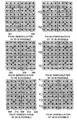
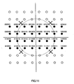
- FIG.5 is a diagram to explain a signal space diagram of 16QAM.
- FIG.6 is a diagram to explain a demodulation method for 16QAM in the adaptive modulation communication system of the present invention.
- black points indicate 16QAM signal points, and white points indicate 64QAM signal points.
- S0 is capable of being demodulated according to a demodulation pattern comprised of a portion 501 at the left side of the vertical axis and a portion 502 at the right side of the vertical axis.
- a demodulation pattern comprised of a portion 501 at the left side of the vertical axis and a portion 502 at the right side of the vertical axis.
- S1 is capable of being demodulated according to a demodulation pattern comprised of a portion 503 at the upper side of the horizontal axis and a portion 504 at the lower side of the horizontal axis.
- a demodulation pattern comprised of a portion 503 at the upper side of the horizontal axis and a portion 504 at the lower side of the horizontal axis.
- S2 is capable of being demodulated according to a demodulation pattern comprised of portions 505 at the sides, opposed to the vertical axis, of axes spaced equal horizontal distances apart from the vertical axis and a portion 506 at the center including the vertical axis.
- S3 is capable of being demodulated according to a demodulation pattern comprised of portions 507 at the sides, opposed to the horizontal axis, of axes spaced equal vertical distances apart from the horizontal axis and a portion 508 at the center including the horizontal axis.
- S0 to S3 are capable of being demodulated in the same way as in 64QAM using demodulation patterns of 64QAM. It is thereby possible to perform the demodulation in 16QAM also without using the information on the modulation scheme (modulation level broadcast signal).
- demodulation using demodulation sections 113-1 to 113-n will be described below when QPSK data is transmitted from the transmitting-side apparatus.
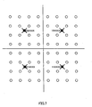
- FIG.7 is a diagram to explain a signal space diagram of QPSK.
- FIG.8 is a diagram to explain a demodulation method for QPSK in the adaptive modulation communication system of the present invention.
- black points indicate QPSK signal points, and white points indicate 64QAM signal points.
- S0 is capable of being demodulated according to a demodulation pattern comprised of a portion 701 at the left side of the vertical axis and a portion 702 at the right side of the vertical axis.
- a demodulation pattern comprised of a portion 701 at the left side of the vertical axis and a portion 702 at the right side of the vertical axis.
- S1 is capable of being demodulated according to a demodulation pattern comprised of a portion 703 at the upper side of the horizontal axis and a portion 704 at the lower side of the horizontal axis.
- a demodulation pattern comprised of a portion 703 at the upper side of the horizontal axis and a portion 704 at the lower side of the horizontal axis.
- S0 and S1 are capable of being demodulated in the same way as in 64QAM using demodulation patterns of 64QAM. It is thereby possible to perform the demodulation in QPSK also without using the information on the modulation scheme (modulation level broadcast signal).
- the repeat will be described below in the case where the receiving-side apparatus detects an error in the error detecting section.
- Two types of repeats are considered in the adaptive modulation communication system of the present invention, i.e., the case of repeat due to a general error and the case of repeat occurring when demodulating data modulated by smaller modulation level than the largest modulation level allowing the demodulation.
- the repeat due to a general error is performed by when an error is detected in the error detecting section, transmitting a repeat request signal for instructing to repeat the erroneous transmit unit to the transmitting-side apparatus.
- the transmitting-side apparatus repeats the data of the transmit unit to be repeated according to the repeat request signal.
- the repeat will be described below which is specific in the adaptive modulation communication system of the present invention and which occurs when demodulating data modulated by smaller modulation level than the largest modulation level allowing the demodulation.
- FIG.9 illustrates a case where the transmitting-side apparatus transmits data #1 to #19 while switching between modulation schemes of QPSK, 16QAM, and 64QAM for each transmission unit.
- Q denotes QPSK
- 16 denotes 16QAM
- 64 denotes 64QAM.
- data #1 to #19 two bits indicate one unit, in QPSK one unit is set as a transmit unit, in 16QAM two units are set as a transmit unit, and in 64QAM three units are set as a transmit unit. Further, an error detecting bit is added for each unit.
- the receiving-side apparatus is provided with demodulation sections corresponding to 64QAM (allowing up to three units as a transmit unit).
- the receiving-side apparatus (Rx) demodulates data #1 as described above. At this point, the receiving-side apparatus detects data #2 and #3 as errors as described above. Then, the receiving-side apparatus transmits a repeat request signal for instructing to repeat data #2 and #3 to the transmitting-side apparatus. In the transmitting-side apparatus,since datato be transmitted next is data #2, transmission is performed starting from data #2 without any change.
- the receiving-side apparatus demodulates data #2 and #3 as described above. At this point, the receiving-side apparatus detects data #4 as an error as described above. Then, the receiving-side apparatus transmits a repeat request signal for instructing to repeat data #4 to the transmitting-side apparatus. In the transmitting-side apparatus, since data to be transmitted next is data #4, and transmission is performed starting from data #4 without any change.
- both repeats occur, i.e., a repeat caused by demodulating data modulated by smaller modulation level than the largest modulation level allowing the demodulation, and a general repeat.
- FIG.10 illustrates a case where the transmitting-side apparatus transmits data #1 to #16 while switching between modulation schemes of QPSK, 16QAM, and 64QAM for each transmit unit.
- Q denotes QPSK
- 16 denotes 16QAM
- 64 denotes 64QAM.
- data #1 to #16 two bits indicate one unit, in QPSK one unit is set as a transmit unit, in 16QAM two units are set as a transmit unit, and in 64QAM three units are set as a transmit unit. Further, an error detecting bit is added for each unit.
- the receiving-side apparatus is provided with demodulation sections corresponding to 64QAM (allowing up to three units as a transmit unit).
- the transmitting-side apparatus (Tx) transmits data #1 by QPSK in a first transmit unit
- the receiving-side apparatus (Rx) demodulates data #1 as described above.
- the receiving-side apparatus detects data #2 and #3 as errors as described above.
- the receiving-side apparatus transmits a repeat request signal for instructing to repeat data #2 and #3 to the transmitting-side apparatus.
- transmission is performed starting from data #2 without any change.
- the transmitting-side apparatus transmits data #2 and #3 by 16QAM in a next transmit unit
- the receiving-side apparatus demodulates data #3 as described above and that data #2 is erroneous.
- the receiving-side apparatus detects data #2 and #4 as errors as described above.
- the receiving-side apparatus transmits a repeat request signal for instructing to repeat data #2 and #4 to the transmitting-side apparatus.
- transmission is performed starting from data #4 along with data #2 having provided the error.
- the transmitting-side apparatus transmits data #7 to #9 by 64QAM in a fifth transmit unit
- the receiving-side apparatus demodulates data #7 and #9 as described above and that data #8 is erroneous.
- the receiving-side apparatus detects data #8 as an error.
- the receiving-side apparatus transmits a repeat request signal for instructing to repeat data #8 to the transmitting-side apparatus.
- transmission is performed starting from data #10 along with data #8 having provided the error.
- the receiving-side apparatus is capable of demodulating the data by a demodulation scheme corresponding to the same modulation method.
- the transmitting-side apparatus transmits data while modulating the data by smaller modulation level than the largest modulation level allowing the demodulation on a demodulation side, it is possible to accurately demodulate data of units actually transmitted. It is thereby possible for the receiving-side apparatus to demodulate all transmitted data without knowing (being aware at all) a modulation scheme of the transmitting-side apparatus.
- the need is eliminated of notifying a modulation scheme (modulation level broadcast signal) from a transmitting-side apparatus to a receiving-side apparatus, and it is thereby possible to use downlink resource effectively. Further, since the need is eliminated of notifying a modulation scheme from a transmitting-side apparatus to a receiving-side apparatus, it is possible to reduce the time during which a modulation level broadcast signal is demodulated and then data is demodulated like the conventional method, and to decrease data delay. Further, it is possible to shorten delay of repeat request.
- pilot signals in a signal space diagram are set as illustrated in FIGs.3 , 5 and 7 .
- pilot signals are assigned respective amplitude and phase of positions (denoted by X in the figure) with the amplitude half the maximum amplitude in the signal space diagram of the largest modulation level scheme. It is thereby possible to share pilot signals in either modulation scheme, and to receive the pilot signals similarly in either modulation scheme.
- pilot point in the signal space diagram of the largest modulation level scheme, is set to a sum of a value of a middle point having amplitude half the maximum amplitude and a predetermined phase rotation, or to a value predetermined times a value of a middle point having amplitude half the maximum amplitude.
- frame format can be determined readily.
- pilot signals can be set with more versatility.
- This embodiment describes a case of applying to modulation schemes where a square root of the number of total signal points is not an integer, for example, 32QAM, 8QAM, and BPSK.
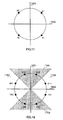
- signal points are arranged in the form of a circle.
- the signal point arrangement in 32QAM is set as illustrated in FIG.11 with eight points in the I(in-phase)-axis direction and with four points in the Q(quadrature)-axis direction.
- the signal point arrangement in 8QAM is set as illustrated in FIG.13 with four points in the I-axis direction and with two points in the Q-axis direction.
- the signal point arrangement in BPSK is set as illustrated in FIG.15 with two points in the I-axis direction.
- the number of signal points in the I-axis direction is made different from the number of signal points in the Q-axis direction.
- the number of points arranged in the same axis direction is set at a number close to a square root of the total signal points as much as possible.
- 8QAM four signal points are arranged in the I-axis direction, while two signal points are arranged in the Q-axis direction, instead of arranging eight signal points in the I-axis direction, while arranging one signal point in the Q-axis direction.
- 32QAM eight signal points are arranged in the I-axis direction, while four signal points are arranged in the Q-axis direction.
- the number of signal points in the I-axis direction is either more or less than the number of signal points in the Q-axis direction.
- the operation of the adaptive modulation communication system according to this embodiment will be described below.
- the operation of the transmitting-side apparatus is the same as in the first embodiment, and is omitted.
- the demodulation in demodulation sections will be described in the case where the transmitting-side apparatus transmits data modulated by an M-ary modulation scheme where a square root of the number of total signal points is not an integer. Also in this case, for each error detecting unit, demodulation is performed independently, and error detection is performed independently. It is thereby possible to accurately transmit data of unit(s) corresponding to the modulation level.
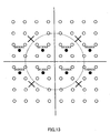
- FIG.11 is a diagram to explain a signal space diagram of 32QAM.
- FIG.12 is a diagram to explain a demodulation method for 32QAM in the adaptive modulation communication system of the present invention.
- black points indicate signal points of 32QAM, and white points indicate signal points of 64QAM.
- S0 is capable of being demodulated according to a demodulation pattern comprised of a portion 1101 at the left side of the vertical axis and a portion 1102 at the right side of the vertical axis.
- a demodulation pattern comprised of a portion 1101 at the left side of the vertical axis and a portion 1102 at the right side of the vertical axis.
- S1 is capable of being demodulated according to a demodulation pattern comprised of a portion 1103 at the upper side of the horizontal axis and a portion 1104 at the lower side of the horizontal axis.
- a demodulation pattern comprised of a portion 1103 at the upper side of the horizontal axis and a portion 1104 at the lower side of the horizontal axis.
- S2 is capable of being demodulated according to a demodulation pattern comprised of portions 1105 at the sides, opposed to the vertical axis, of axes spaced equal horizontal distances apart from the vertical axis and a portion 1106 at the center including the vertical axis.
- bits at the fifth left as viewed in the figure S4 are "0" at a first portion, including the vertical axis (Q-axis), between axes spaced equal horizontal distances apart from the vertical axis, are "1" at second portions, with the same horizontal width as the first portion, at opposite sides of the first portion, and are "0" at third portions outside the second portions.
- S4 is capable of being demodulated according to a demodulation pattern comprised of the first portion 1109, including the vertical axis, between axes spaced equal horizontal distances apart from the vertical axis, the second portions 1110, with the same horizontal width as the first portion 1109, at opposite sides of the first portion, and the third portions 1109 outside the second portions 1110.
- bits at the sixth left as viewed in the figure are "0" at a first portion, including the horizontal axis (I-axis), between axes spaced equal vertical distances apart from the horizontal axis, are "1" at second portions, with the same vertical width as the first portion, at opposite sides of the first portion, and are "0" at third portions outside the second portions .
- S5 is capable of being demodulated according to a demodulation pattern comprised of the first portion 1111, including the horizontal axis, between axes spaced equal vertical distances apart from the horizontal axis, the second portions 1112, with the same vertical width as the first portion 1111, at opposite sides of the first portion, and the third portions 1111 outside the second portions 1112.
- S0 to S2, S4 and S5 are capable of being demodulated in the same way as in 64QAM using demodulation patterns of 64QAM. In this way it is also possible to perform demodulation in 32QAM without using information on the modulation scheme (modulation level broadcast signal).
- the demodulation will be described below in the case where the transmitting-side apparatus transmits data of 8QAM.
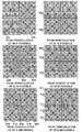
- FIG.13 is a diagram to explain a signal space diagram of 8QAM.
- FIG.14 is a diagram to explain a demodulation method for 8QAM in the adaptive modulation communication system of the present invention.
- black points indicate signal points of 8QAM, and white points indicate signal points of 64QAM.
- S0 is capable of being demodulated according to a demodulation pattern comprised of a portion 1301 at the left side of the vertical axis and a portion 1302 at the right side of the vertical axis.
- a demodulation pattern comprised of a portion 1301 at the left side of the vertical axis and a portion 1302 at the right side of the vertical axis.
- S1 is capable of being demodulated according to a demodulation pattern comprised of a portion 1303 at the upper side of the horizontal axis and a portion 1304 at the lower side of the horizontal axis.
- a demodulation pattern comprised of a portion 1303 at the upper side of the horizontal axis and a portion 1304 at the lower side of the horizontal axis.
- S2 is capable of being demodulated according to a demodulation pattern comprised of portions 1305 at the sides, opposed to the vertical axis, of axes spaced equal horizontal distances apart from the vertical axis and a portion 1306 at the center including the vertical axis.
- S0 to S2 are capable of being demodulated in the same way as in 64QAM using demodulation patterns of 64QAM. It is thereby possible to perform the demodulation in 8QAM also without using the information on the modulation scheme (modulation level broadcast signal).
- the demodulation will be described below in the case where the transmitting-side apparatus transmits data of BPSK.
- FIG.15 is a diagram to explain a signal space diagram of BPSK.
- FIG.16 is a diagram to explain a demodulation method for BPSK in the adaptive modulation communication system of the present invention.
- black points indicate signal points of BPSK, and white points indicate signal points of 64QAM.
- S0 is capable of being demodulated according to a demodulation pattern comprised of a portion 1501 at the left side of the vertical axis and a portion 1502 at the right side of the vertical axis.
- a demodulation pattern comprised of a portion 1501 at the left side of the vertical axis and a portion 1502 at the right side of the vertical axis.
- the receiving-side apparatus is capable of demodulating the data by a demodulation scheme corresponding to the same modulation scheme.
- the transmitting-side apparatus transmits data while modulating the data by smaller modulation level than the largest modulation level allowing the demodulation on a demodulation side, it is possible to accurately demodulate data of units actually transmitted. It is thereby possible for the receiving-side apparatus to demodulate all transmitted data without knowing (being aware at all) a modulation scheme of the transmitting-side apparatus.
- the need is eliminated of notifying a modulation scheme (modulation level broadcast signal) from a transmitting-side apparatus to a receiving-side apparatus, and it is thereby possible to use downlink resource effectively. Further, since the need is eliminated of notifying a modulation scheme from a transmitting-side apparatus to a receiving-side apparatus, it is possible to reduce the time during which a modulation level broadcast signal is demodulated and then data is demodulated like the conventional method, and to decrease data delay. Further, it is possible to shorten delay of repeat request.
- pilot signals in a signal space diagram are set as illustrated in FIGs.11 , 13 and 15 .
- pilot signals are assigned amplitude and phase of center positions (denoted by X in the figure) in quadrants, respectively, in the signal space diagram. It is thereby possible to share pilot signals in either modulation scheme, and to receive the pilot signals similarly in either modulation scheme.
- pilot points are set at positions spaced apart from respective axes by a distance corresponding to a predetermined phase rotation, or at positions set corresponding to the amplitude predetermined number times the predetermined amplitude.
- frame format can be determined readily.
- pilot signals can be set with more versatility.
- This embodiment describes a case of applying the adaptive modulation communication system of the present invention to star-16QAM and 16PSK modulation schemes.
- the case will be described of applying the adaptive modulation communication system of the present invention to star-16QAM and 16PSK modulation schemes, using 8PSK.
- FIG.17 is a diagram to explain a signal space diagram of QPSK.
- FIG.18 is a diagram to explain a signal space diagram of 8PSK.
- a first bit such bits are "0" above horizontal axis 1602, while being “1” under horizontal axis 1602, with axis 1602 as a boundary.
- a second bit such bits are "0" at the left of vertical axis 1601, while being “1” at right of vertical axis 1601, as viewed in the figure, with vertical axis 1601 as a boundary. Accordingly, by determining the foregoing, it is possible to demodulate 2 bits of QPSK.
- the most significant bits and second significant bits are capable of being demodulated as the same way as in QPSK.
- the least significant bits are determined using portions 1701 to 1704 each between axes at 45° to vertical axis 1601 and horizontal axis 1602. In other words, such bits are "0" in portions 1701 and 1703 (where an absolute value of vertical axis 1601 is greater than that of horizontal axis 1602), while being “1” in portions 1702 and 1704 (where an absolute value of vertical axis 1601 is smaller than that of horizontal axis 1602). Accordingly, by determining the foregoing, it is possible to demodulate information of three bits of 8PSK.
- FIG.19 is a diagram to explain a signal space diagram of star-16QAM.
- the most significant bits to third significant bits are capable of being demodulated in the same way as in 8PSK.
- a predetermined threshold with respect to the amplitude.
- the present invention is applicable to a casewhere a plurality of thresholds is used with respect to the amplitude.
- a plurality of thresholds for the amplitude it is possible to make an amplitude determination up to less significant bits, thereby enabling demodulation of signals modulated -by star-QAM of larger modulation level.
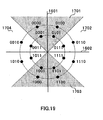
- FIG.20 is a diagram to explain a signal space diagram of 16PSK.
- the most significant bits to third significant bits are capable of being demodulated in the same way as in 8PSK.
- the least significant bits are determined using portions 1901 to 1908 each between axes each at 22.5° and 67.5° to vertical axis 1601 and horizontal axis 1602. In other words, such bits are "0" in portions 1901, 1903, 1905 and 1907 (portions between axes of 22.5° and 67.5° including vertical axis 1601 or horizontal axis 1602), while being “1” in portions 1902, 1904, 1906 and 1908 (portions between axes of 22.5° and 67.5° with no vertical axis 1601 or horizontal axis 1602 included). Accordingly, by determining the foregoing, it is possible to demodulate information of four bits of 16PSK.
- phase determination axes phase determination axes passing through the origin point in the signal space diagram
- present invention is applicable to a case of using three or more types of phase determination axes with respect to the least significant bit.
- three or more phase determination axes with respect to the least significant bit it is possible to make a phase determination up to less significant bits, thereby enabling demodulation of signals modulated by modulation scheme of larger modulation level.
- demodulators capable of demodulating signals modulated by star-QAM illustrated in FIGs.19 and 20 to demodulate modulated signals modulated by an upper modulation scheme (modulation scheme with less bits assigned to one symbol).
- an upper modulation scheme for example, QPSK and 8PSK
- the phase determination and amplitude determination in the adaptive modulation communication system using star-QAM are capable of being carried out in a combination thereof.
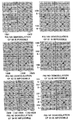
- FIG.21 is a diagram to explain a case of transmitting signals in 8PSK.
- S0 to S2 indicate bits assigned to the most to third significant bits respectively in 8PSK.
- Signals of 24 bits (0 to 23) are divided into three groups, while adding error detecting bits C0 to C2 to bits 0 to 7, adding error detecting bits C3 to C5 to bits 8 to 15, and adding error detecting bits C6 to C8 to bits 16 to 23, and resultant signals are transmitted.
- a receiving side does not know that either modulation scheme among QPSK, 8PSK and star-16QAM is used to transmit signals.
- the demodulation is performed while assuming the modulation scheme as star-16QAM which is the largest-modulation-level modulation scheme. Since it is possible to demodulate S0 to S2 accurately as described even in demodulating as star-16QAM, an error is not detected. However, since S3 is not transmitted, an error is detected thereon.
- the receiving side accepts bits 0 to 23 of S0 to S2 as correct signals.
- error detecting bits are added every same bits collectively over a plurality of symbols and a receiving side performs error detection, whereby it is possible to detect only transmitted bits as effective bits. In this way, it is possible to accurately perform demodulation without a communication party notifies of a modulation scheme used in transmission.
- the present invention is applicable to a case where the largest-modulation-level modulation scheme is an M-ary modulation scheme whose modulation level is exceeding 16, and further to a case where a phase modulation scheme is not a star modulation scheme. Moreover, the present invention is also applicable to a case where an M-ary modulation scheme has modulation level both in the amplitude and phase.
- the modulation scheme is determined based on channel quality information such as received SIR (Signal to Interference Ratio), received electric field intensity, error rate, and observation of transmit power control command.
- the channel quality may be of broadcast information indicative of a result measured in the receiving-side apparatus.
- TDD Time Division Duplex
- the channel quality from a repeat request signal may be determined to reflect in change of modulation scheme.
- the channel quality is estimated from the repeat request signal, and based on the estimated result, the modulation scheme is varied as appropriate. For example, in the case where signals of 16QAM are transmitted and for example, three or more repeat requests are received, it may be determined that 16QAM is not optimal, and the modulation scheme is switched to a smaller-modulation-level modulation scheme such as 8QAM. Further, in the case of receiving two repeat requests, it may be determined that all the bits are properly transmitted, and the modulation scheme is continued or switched to a larger-modulation-level modulation scheme.
- the channel quality from the repeat request to reflect in change of modulation scheme it may be possible to reflect a plurality of previous repeat request results. For example, in the case where signals of 16QAM are transmitted and four or more repeat requests are received, it may be determined that 16QAM is not optimal, and the modulation scheme is switched to a smaller-modulation-level modulation scheme such as 8QAM. In the case of receiving three repeat requests, the determination is made with previous repeat request included, and in the case of receiving three repeat requests twice in row, the modulation scheme is switched to a smaller-modulation-level modulation scheme such as 8QAM. Further, in the case of receiving two repeat requests, it may be determined that all the bits are properly transmitted, and the modulation scheme is continued or switched to a larger-modulation-level modulation scheme.
- the transmitting-side does not transmit any information on a modulation scheme at all.
- the information is broadcast on a broadcast channel that a base station supports only BPSK, QPSK, 8QAM and 16QAM.
- a receiving-side apparatus may notify modulation schemes that the receiving-side apparatus supports, for example, in communicating protocols with a transmitting-side apparatus. It is thereby possible for the transmitting-side apparatus to transmit signals while selecting a modulation scheme from only among modulation schemes that the receiving-side apparatus supports. As a result, it may be possible to carry out the control in the above embodiments as appropriate corresponding to what the receiving-side apparatus supports. For example, when a communication terminal supports only up to 16QAM, a base station performs only up to 16QAM only for the communication terminal. At this point, the base station uses only up to 16QAM even when up to 64QAM are available. In this case, since radio resource is wasted, such a terminal may be imposed a penalty such as a fine.
- the base station in determining modulation scheme candidates , it may be possible to determine the candidates corresponding to an average state of a channel between a transmitting-side apparatus and receiving-side apparatus. For example, when a communication terminal exists at a place far from a base station and the base station determines that only BPSK to 8QAM can be used, the base station notifies the communication terminal of transmitting signals according to BPSK to 8QAM, using a low-rate control signal or first protocol. In this way, the communication terminal does not need to receive signals corresponding to 32QAM and 64QAM, and is capable of suppressing wasteful power consumption.
- the base station is capable of determining a candidate range of modulation scheme using selection histogram of previous modulation schemes, statistics and average of channel quality information. Further, when data is not transmitted during a long period, it may be possible that such a message is notified that data is not transmitted during a long period, and that based on the message, the candidate range of modulation scheme is determined.
- the repeat error correcting algorithm is not limited in particular in the above first to third embodiments. Accordingly, as a repeat error correcting algorithm, examples are Stop and Wait ARQ, Go Back N ARQ, Selective Repeat ARQ and Hybrid ARQ.
- the receiving-side apparatus is capable of performing weighting with likelihood to combine amplitude.
- the transmitting-side apparatus knows the transmitted data, and therefore is capable of making such a determination. However, the receiving-side apparatus does not know the transmitted data, and therefore needs to perform both transmissions of repeat and first transmission. In this case, when an information amount in repeat is different from a general transmit data amount, the information amount is brought coincident by transmitting a plurality of repeats successively or collecting a plurality of repeats.
- the present invention is not limited to the above first to third embodiments, and is capable of being carried out with various modifications thereof.
- the above embodiments describe the case that the largest modulation level is 64 in the receiving-side apparatus
- the present invention is applicable similarly to a case that the largest modulation level in the receiving-side apparatus exceeds 64 such as 128 and 256.
- Any modulation scheme may be a candidate corresponding to performance. Accordingly, modulation levels used in the first and second embodiments are not limited in particular.
- the adaptive modulation communication system of the present invention is applicable to a digital radio communication system between a communication terminal and base station, and broadcast system.
- An adaptive modulation communication system of the present invention is an adaptive modulation communication system that adaptively varies a modulation scheme for each transmit unit, and adopts a configuration where a transmitting-side apparatus sets different error detecting units corresponding to bit position, and transmits data subjected to error detecting processing on a different error detecting unit basis corresponding to bit position, and a receiving-side apparatus performs demodulation independently for each of the error detecting units using different demodulation patterns to obtain received data.
- the receiving-side apparatus even when the transmitting-side apparatus uses either modulation scheme among M-ary modulation schemes to transmit signals, it is possible for the receiving-side apparatus to demodulate data by a demodulation method corresponding to the modulation scheme.
- the receiving-side apparatus is capable of demodulating all transmitted data without knowing (being aware at all) a modulation scheme of the transmitting-side apparatus.
- the need is eliminated of notifying a modulation scheme (modulation level broadcast signal) from a transmitting-side apparatus to a receiving-side apparatus, and it is thereby possible to use downlink resource effectively. Further, since the need is eliminated of notifying a modulation scheme from a transmitting-side apparatus to a receiving-side apparatus, it is possible to reduce the time during which a modulation level broadcast signal is demodulated and then data is demodulated like the conventional method, and to decrease data delay. Further, it is possible to shorten delay of repeat request.
- the adaptive modulation communication system of the present invention adopts a configuration, in the above configuration, where the modulation scheme is varied adaptively among M-ary modulation schemes each with a square root of the number of signal points being an integer.
- the adaptive modulation communication system of the present invention adopts a configuration, in the above configuration, where the modulation scheme is varied adaptively among M-ary modulation schemes each with a square root of the number of signal points being not an integer.
- the adaptive modulation communication system of the present invention adopts a configuration, in the above configuration, where the modulation scheme is varied adaptively among M-ary modulation schemes each using phase determination axes passing through the origin point in the signal space diagram.
- the adaptive modulation communication system of the present invention adopts a configuration, in the above configuration, where the M-ary modulation schemes using phase determination axes passing through the origin point in the signal space diagram are modulation schemes in which identification in an amplitude direction is performed.
- the adaptive modulation communication system of the present invention adopts a configuration, in the above configuration, where error correcting coding is performed collectively every a plurality of bits, and the receiving-side apparatus detects bits transmitted from the transmitting-side apparatus as effective bits by performing error detection.
- the adaptive modulation communication system of the present invention adopts a configuration, in the above configuration, where an arrangement of signal points is set so that a difference between the number of signal points in the I-axis direction and the number of signal points in the Q-axis direction is small. It is thereby possible to improve transmission efficiency when there is a difference between the number of signal points in the I-axis direction and the number of signal points in the Q-axis direction.
- the adaptive modulation communication system of the present invention adopts a configuration, in the above configuration, where positions of pilot signals are set using a value half the maximum amplitude in the signal space diagram of an M-ary modulation scheme having the largest modulation level.
- the adaptive modulation communication system of the present invention adopts a configuration, in the above configuration, where a repeat request is performed for each error detecting unit.
- the adaptive modulation communication system of the present invention adopts a configuration, in the above configuration, where the modulation scheme is varied adaptively based on channel quality estimated from the repeat request.
- a transmitting apparatus of the present invention adopts a configuration provided with a section that sets different error detecting units corresponding to bit position, and a section that transmits data subjected to error detecting processing on a different error detecting unit basis corresponding to bit position.
- a receiving apparatus of the present invention adopts a configuration provided with a section that receives data subjected to error detecting processing on a different error detecting unit basis corresponding to bit position, and a section that demodulates the data independently for each error detecting unit using different demodulation patterns to obtain received data
- the adaptive modulation communication system of the present invention since the need is eliminated of notifying information on a modulation scheme or the like from a transmitting-side apparatus to a receiving-side apparatus, it is possible to use downlink resource effectively. Further, it is possible to reduce the time during which the information on the modulation scheme or the like is demodulated and then data is demodulated, and to decrease processing delay. As a result, it is also possible to shorten delay of repeat request.
- the present invention is applicable to an adaptive modulation communication system used in a digital radio communication system.
Landscapes
- Engineering & Computer Science (AREA)
- Signal Processing (AREA)
- Computer Networks & Wireless Communication (AREA)
- Digital Transmission Methods That Use Modulated Carrier Waves (AREA)
- Mobile Radio Communication Systems (AREA)
Abstract
Description
- The present invention relates to a new adaptive modulation communication system used in a digital radio communication system.
- With recent advances in internet-related techniques, the internet has enabled various services such as music distribution to be provided. Such services increase downlink transmit amounts. In order to achieve such services having increased transmit amounts, great expectations are placed on fast transmission over the downlink, and various techniques have been developed on the downlink fast transmission. One of the techniques is an adaptive modulation communication system where on a transmitting side a modulation scheme is adaptively varied to perform efficient data transmission.
- A conventional adaptive modulation communication system will be described with reference to
FIG.1 . - In the adaptive modulation communication system illustrated in
FIG.1 , CQES(channel quality estimating section) 1 in a transmitting-side apparatus estimates a channel quality using a received signal. The estimated channel quality information is output to MLDS (modulation level determining section) 2. MLDS 2 determines a modulation level based on the channel quality information. For example, when the channel quality is good, MLDS 2 increases the modulation level, while decreasing the modulation level when the channel quality is poor. A broadcast signal indicative of modulation level is output tobuffer 5, while being output to modulation section 6-2. - Transmit data is output to EDBAS(error detecting bit adding section) 3, where an error detecting bit is added. The transmit data with the error detecting bit added thereto is output to ECCS(error correcting coding section) 4 to undergo error correcting coding. The transmit data subjected to the error correcting coding is output to
buffer 5 to be stored therein. - To
buffer 5 is input the modulation level broadcast signal output from modulationlevel determining section 2. According to the modulation level broadcast signal, the transmit data is output to modulation section 6-1 for each modulation unit of the determined modulation scheme. - Modulation section 6-2 modulates the modulation level broadcast signal to output to adder 7. Modulation section 6-1 modulates the transmit data output from
buffer 5 to output to adder 7. Adder 7 multiplexes the modulation level broadcast signal and the transmit data. - The multiplexed signal is output to
radio transmission section 8, is subjected to the predetermined radio transmission processing (for example, D/A conversion and upconverting) inradio transmission section 8, and the resultant radio signal is transmitted to a receiving-side apparatus (communication party) viaantenna 9. - The signal transmitted from the transmitting-side apparatus is received in
radio reception section 13 viaantenna 12 in the receiving-side apparatus.Radio reception section 13 performs the predetermined radio reception processing (for example, downconverting and A/D conversion) on the received signal. - The signal subjected to the radio reception processing is demultiplexed to the modulation level broadcast signal and data, and the signal and data is output to
demodulation section 14. Specifically, the data is output to demodulation section 14-1, and the modulation level broadcast signal is output to demodulation section 14-2. Demodulation section 14-2 demodulates the modulation level broadcast signal to obtain information on the modulation scheme (modulation level) on the transmitting-side apparatus. The information on the modulation scheme is output to demodulation section 14-1. - According to the information on the modulation scheme output from demodulation section 14-2, demodulation section 14-1 demodulates the data. The demodulated data is output to error correcting
decoding section 15 to undergo error correcting decoding. Then, the error-correcting-decoded data is output to error detectingsection 16 to undergo error detection. An output oferror detecting section 16 is received data. Further, a detection result (a result when an error is detected) inerror detecting section 16 is output tomodulation section 17 as a repeat request signal. -
Modulation section 17 modulates the repeat request signal as well as the transmit data. The modulated signal is output toradio transmission section 18.Radio transmission section 18 performs the predetermined radio transmission processing on the modulated signal. The signal subjected to the radio transmission processing is transmitted to the transmitting-side apparatus (communication party) viaantenna 12. - The signal including the repeat request signal is received in
radio reception section 10 viaantenna 9.Radio reception section 10 performs the predetermined radio reception processing on the received signal. The signal subjected to the radio reception processing is output todemodulation section 11.Demodulation section 11 demodulates the data and the repeat request signal. The data becomes received data, and the repeat request signal is output tobuffer 5. According to the repeat request signal,buffer 5 outputs data targeted for the repeat to modulation section 6-1. - As described above, in the aforementioned adaptive modulation communication system, when a modulation scheme is adaptively varied to transmit signals, the information on the modulation scheme (modulation level or the like) is multiplexed on a transmit signal in transmitting signals. As a result, on the receiving side it is possible to perform demodulation according to the information on the modulation scheme even when the modulation scheme is varied adaptively.
- However, in the conventional adaptive modulation communication system, the receiving-side apparatus is not capable of demodulating data unless the transmitting-side notifies the receiving-side apparatus of the information on the modulation scheme (modulation level broadcast signal). Accordingly, it is necessary to transmit the information of the modulation level broadcast signal with greatly high quality. Further, demodulating data is started only after the modulation level broadcast signal is demodulated, and furthermore, an erroneous modulation level broadcast signal disables the reception even when the data quality is high.
- Meanwhile, a method is proposed in which a receiving-side apparatus determines a modulation scheme used in a transmitting-side apparatus using a signal variance, but since the detection accuracy is low in this method, is not very practical.
-
EP 0 531 046 A2 describes a communication system, in which the receiver is provided with plural demodulators configured with different modulation schemes. Upon receiving a signal all demodulators individually try to demodulate a received signal (modulation symbol) using a respective modulation scheme specific to the demodulators, respectively. Thereupon, error values are calculated for each demodulator and the demodulator with the lowest probability of error is selected to output the demodulated data. - It is an object of the present invention to provide an adaptive modulation communication system enabling excellent demodulation on a receiving side without notifying information on a modulation scheme when adaptive modulation communications are performed.
- The inventor of the present invention noted the state of mapping per bit basis in a signal space diagram in M-ary modulation, found out demodulation is allowed independently of a modulation scheme used in a transmitting-side apparatus by determining demodulation patterns for each predetermined unit, and carried out the present invention.
- It is a gist of the present invention that in an adaptive modulation communication system where a modulation scheme is varied adaptively for each transmit unit, a transmitting-side apparatus sets different error detecting units corresponding to bit position, and transmits data subjected to error detecting processing on a different error detecting unit basis corresponding to bit position, and a receiving-side apparatus performs demodulation independently using different demodulation patterns for each error detecting unit to obtain received data.
-
-
FIG.1 is a block diagram illustrating a configuration of a conventional adaptive modulation communication system; -
FIG.2 is a block diagram illustrating a configuration of an adaptive modulation communication system according to embodiments of the present invention; -
FIG.3 is a diagram to explain a signal space diagram of 64QAM; -
FIGs.4A to 4F are diagrams to explain a demodulation method for 64QAM in the adaptive modulation communication system of the present invention; -
FIG.5 is a diagram to explain a signal space diagram of 16QAM; -
FIGs.6A to 6F are diagrams to explain a demodulation method for 16QAM in the adaptive modulation communication system of the present invention; -
FIG.7 is a diagram to explain a signal space diagram of QPSK; -
FIGs. 8A to 8F are diagrams to explain a demodulation method for QPSK in the adaptive modulation communication system of the present invention; -
FIG.9 is a diagram to explain transmission and reception in the adaptive modulation communication system of the present invention; -
FIG.10 is another diagram to explain transmission and reception in the adaptive modulation communication system of the present invention; -
FIG. 11 is a diagram to explain a signal space diagram of 32QAM; -
FIGs.12A to 12F are diagrams to explain a demodulation method for 32QAM in the adaptive modulation communication system of the present invention; -
FIG.13 is a diagram to explain a signal space diagram of 8QAM; -
FIGs.14A to 14F are diagrams to explain a demodulation method for 8QAM in the adaptive modulation communication system of the present invention; -
FIG.15 is a diagram to explain a signal space diagram of BPSK; -
FIGs.16A to 16F are diagrams to explain a demodulation method for BPSK in the adaptive modulation communication system of the present invention; -
FIG.17 is a diagram to explain a signal space diagram of QPSK; -
FIG.18 is a diagram to explain a signal space diagram of 8PSK; -
FIG.19 is a diagram to explain a signal space diagram of star-16QAM; -
FIG.20 is a diagram to explain a signal space diagram of 16PSK; and -
FIG.21 is a diagram to explain a case of transmitting signals in 8PSK. - Embodiments of the present invention will be described below specifically with reference to accompanying drawings.
-
FIG.2 is a block diagram illustrating a configuration of an adaptive modulation communication system according to the embodiments of the present invention. - In the adaptive modulation communication system illustrated in
FIG.2 , CQES(channel quality estimating section) 101 in a transmitting-side apparatus estimates a channel quality using a received signal. The estimated channel quality information is output to MLDS(modulation level determining section) 102.MLDS 102 determines a modulation level based on the channel quality information. For example, when the channel quality is good,MLDS 102 increases the modulation level, while decreasing the modulation level when the channel quality is poor. The information on the modulation level is output to buffer 105, while being output tomodulation section 106. - Transmit data is output to EDBAS(error detecting bit adding section) 103, where an error detecting bit is added for each error detection unit. The transmit data with the error detecting bit added thereto is output to ECCS(error correcting coding section) 104 to undergo error correcting coding. The transmit data subjected to the error correcting coding is output to buffer 105 to be stored therein.
- To buffer 105 is input the modulation level information output from
MLDS 102. According to the modulation level information, the transmit data is output tomodulation section 106 for each modulation unit of the determined modulation scheme. -
Modulation section 106 modulates the transmit data, and outputs the modulated signal toradio transmission section 107. The transmit signal is subjected to the predetermined radio transmission processing (for example, D/A conversion and upconverting) inradio transmission section 107, and the resultant radio signal is transmitted to a receiving-side apparatus (communication party) viaantenna 108. - The signal transmitted from the transmitting-side apparatus is received in
radio reception section 112 viaantenna 111 in the receiving-side apparatus.Radio reception section 112 performs the predetermined radio reception processing (for example, downconverting and A/D conversion) on the received signal. - The signal subjected to the radio reception processing is output to demodulation sections 113-1 to 113-n for each predetermined unit
- Then, demodulation sections 113-1 to 113-n demodulate signals for each predetermined unit according to respective demodulation patterns.
- The demodulated data is output to ECDS(error correcting decoding sections) 114-1 to 114-n respectively to undergo error correcting decoding. Then, the error-correcting-decoded data is output to error detecting sections 115-1 to 115-n respectively to undergo error detection. Outputs of error detecting sections 115-1 to 115-n are received data. Further, a detection result (a result when an error is detected) in each of error detecting sections 115-1 to 115-n is output to
modulation section 116 as a repeat request signal. -
Modulation section 116 modulates the repeat request signal as well as the transmit data. The modulated signal is output toradio transmission section 117.Radio transmission section 117 performs the predetermined radio transmission processing on the modulated signal. The signal subjected to the radio transmission processing is transmitted to the transmitting-side apparatus (communication party) viaantenna 111. - The signal including the repeat request signal is received in
radio reception section 109 viaantenna 108.Radio reception section 109 performs the predetermined radio reception processing on the received signal. The signal subjected to the radio reception processing is output todemodulation section 110.Demodulation section 110 demodulates the data and repeat request signal. The data becomes received data, and the repeat request signal is output to buffer 105. According to the repeat request signal, buffer 105 outputs data targeted for the repeat tomodulation section 106. - The operation in the adaptive modulation communication system with the above configuration will be described below. The transmitting-side apparatus divides transmit data into predetermined units, and adds an error detecting bit such as CRC (Cyclic Redundancy Check) for each unit in
EDBAS 103. - At this point, the number of units of a predetermined unit is made different corresponding to modulation scheme in performing M-ary modulation. For example, in BPSK one unit is set as a transmit unit in a slot, in QPSK two units are set as a transmit unit in a slot, in 8QAM three units are set as a transmit unit in a slot, in 16QAM four units are set as a transmit unit in a slot, in 32QAM five units are set as a transmit unit in a slot, in 64QAM six units are set as a transmit unit in a slot, and the transmit unit is concurrently transmitted. Each unit is capable of undergoing error detection independently. In this way, it is possible to perform the error correction and error detection only once, and a difference in transmit rate corresponding to modulation scheme can be represented by the number of units transmitted concurrently, thereby facilitating resource allocation in performing M-ary modulation.
- It may be possible to set as the unit a signal bit, or two bits or more. For example, 64QAM is set for six units in a slot, and one bit may be set as one unit, or two or more bits are set as one unit. Specifically, it may be possible to with two bits set as one unit, set a unit as a transmit unit in QPSK, set two units as a transmit unit in 16QAM, and set three units as a transmit unit in 64QAM, to transmit concurrently. In this way, it is possible to readily perform resource allocation in performing M-ary modulation, using less candidates.
- The transmit data with the error detecting bit added as described above is subjected to the predetermined error correcting coding in
ECCS 104, and the coded signal is output to buffer 105. To buffer 105 is input the information on the modulation level determined from the channel quality estimated based on the received signal. Based on the information on the modulation level,buffer 105 outputs the transmit data for each transmit unit of the determined modulation scheme tomodulation section 106. - The transmit data is modulated in
modulation section 106, the modulated signal is subjected to the predetermined radio transmission processing inradio transmission section 107, the radio signal is transmitted to the receiving-side apparatus (communication party) fromantenna 108. - In the receiving-side apparatus, data is output to demodulation sections 113-1 to 113-n for each unit set in the transmitting-side apparatus, and demodulation sections 113-1 to 113-n demodulate the data according to respective demodulation patterns.
- It is herein assumed that the transmitting-side apparatus determines 64QAM as the modulation scheme, sets one unit at one bit, and transmits six units as a transmit unit, in other words, that the apparatus adds an error detecting bit for each error detection unit and transmits six bits as a transmit unit.
-
FIG.3 is a diagram to explain a signal space diagram of 64QAM.FIG.4 is a diagram to explain a demodulation method for 64QAM in the adaptive modulation communication system of the present invention. InFIG.3 , with respect to the most significant bit (bit at the leftmost as viewed in the figure) S0, such bits are "0" at the left side of the vertical axis (Q-axis), while being "1" at the right side of the vertical axis. Accordingly, as shown inFIG.4A , S0 is capable of being demodulated according to a demodulation pattern comprised of aportion 301 at the left side of the vertical axis and aportion 302 at the right side of the vertical axis. In other words, it is possible to demodulate such bits in theportion 301 at the left side of the vertical axis to "0", while demodulating such bits in theportion 302 at the right side of the vertical axis to "1". - In
FIG.3 , with respect to a second significant bit (bit at the second left as viewed in the figure) S1, such bits are "0" at the upper side of the horizontal axis (I-axis), while being "1" at the lower side of the horizontal axis. Accordingly, as shown inFIG.4B , S1 is capable of being demodulated according to a demodulation pattern comprised of aportion 303 at the upper side of the horizontal axis and aportion 304 at the lower side of the horizontal axis. In other words, it is possible to demodulate such bits in theportion 303 at the upper side of the horizontal axis to "0", while demodulating such bits in theportion 304 at the lower side of the horizontal axis to "1". - In
FIG.3 , with respect to a third significant bit (bit at the third left as viewed in the figure) S2, such bits are "0" at the sides, opposed to the vertical axis (Q-axis), of axes (existing at the midpoint of signal points in the horizontal direction) spaced equal horizontal distances apart from the vertical axis, while being "1" at the center portion including the vertical axis. Accordingly, as shown inFIG.4C , S2 is capable of being demodulated according to a demodulation pattern comprised ofportions 305 at the sides, opposed to the vertical axis, of axes spaced equal horizontal distances apart from the vertical axis and aportion 306 at the center including the vertical axis. In other words, it is possible to demodulate such bits in theportions 305 at the sides, opposed to the vertical axis, of axes spaced equal horizontal distances apart from the vertical axis to "0", while demodulating such bits in theportion 306 at the center including the vertical axis to "1". - In
FIG.3 , with respect to a fourth significant bit (bit at the fourth left as viewed in the figure) S3, such bits are "0" at the sides, opposed to the horizontal axis (I-axis), of axes (existing at the midpoint of signal points in the vertical direction) spaced equal vertical distances apart from the horizontal axis, while being "1" at the center portion including the horizontal axis. Accordingly, as shown inFIG.4D , S3 is capable of being demodulated according to a demodulation pattern comprised ofportions 307 at the sides, opposed to the horizontal axis, of axes spaced equal vertical distances apart from the horizontal axis and aportion 308 at the center including the horizontal axis. In other words, it is possible to demodulate such bits in theportions 307 at the sides, opposed to the horizontal axis, of axes spaced equal vertical distances apart from the horizontal axis to "0", while demodulating such bits in theportion 308 at the center including the horizontal axis to "1". - In
FIG.3 , with respect to a fifth significant bit (bit at the fifth left as viewed in the figure) S4, such bits are "0" at a first portion, including the vertical axis (Q-axis), between axes spaced equal horizontal distances apart from the vertical axis, are "1" at second portions, with the same horizontal width as the first portion, at opposite sides of the first portion, and are "0" at third portions outside the second portions. Accordingly, as shown inFIG.4E , S4 is capable of being demodulated according to a demodulation pattern comprised of thefirst portion 309, including the vertical axis, between axes spaced equal horizontal distances apart from the vertical axis, thesecond portions 310, with the same horizontal width as thefirst portion 309, at opposite sides of the first portion, and thethird portions 309 outside thesecond portions 310. In other words, it is possible to demodulate such bits to "0" in thefirst portion 309, including the vertical axis, between axes spaced equal horizontal distances apart from the vertical axis, such bits to "1" in thesecond portions 310, with the same horizontal width as thefirst portion 309, at opposite sides of the first portion, and such bits to "0" in thethird portions 309 outside thesecond portions 310. - In
FIG.3 , with respect to a least significant bit (bit at the sixth left as viewed in the figure) S5, such bits are "0" at a first portion, including the horizontal axis (I-axis), between axes spaced equal vertical distances apart from the horizontal axis, are "1" at second portions , with the same vertical width as the first portion, at opposite sides of the first portion, and are "0" at third portions outside the second portions. Accordingly, as shown inFIG.4F , S5 is capable of being demodulated according to a demodulation pattern comprised of thefirst portion 311, including the horizontal axis, between axes spaced equal vertical distances apart from the horizontal axis, thesecond portions 312, with the same vertical width as thefirst portion 311, at opposite sides of the first portion, and thethird portions 311 outside thesecond portions 312. In other words, it is possible to demodulate such bits to "0" in thefirst portion 311, including the horizontal axis, between axes spaced equal vertical distances apart from the horizontal axis, such bits to "1" in thesecond portions 312, with the same vertical width as thefirst portion 311, at opposite sides of the first portion, and such bits to "0" in thethird portions 311 outside thesecond portions 312. - Thus, demodulation sections 113-1 to 113-n demodulate data according to the above-mentioned respective demodulation patterns. It is thereby possible to perform demodulation in 64QAM without using information on the modulation scheme (modulation level broadcast signal).
- The demodulation using demodulation sections 113-1 to 113-n will be described below when 16QAM data is transmitted from the transmitting-side apparatus.
-
FIG.5 is a diagram to explain a signal space diagram of 16QAM.FIG.6 is a diagram to explain a demodulation method for 16QAM in the adaptive modulation communication system of the present invention. InFIG.5 , black points indicate 16QAM signal points, and white points indicate 64QAM signal points. - In
FIG.5 , with respect to a most significant bit (bit at the leftmost as viewed in the figure) S0, such bits are "0" at the left side of the vertical axis (Q-axis), while being "1" at the right of the vertical axis. Accordingly, as shown inFIG.6A , S0 is capable of being demodulated according to a demodulation pattern comprised of aportion 501 at the left side of the vertical axis and aportion 502 at the right side of the vertical axis. In other words, it is possible to demodulate such bits in theportion 501 at the left side of the vertical axis to "0", while demodulating such bits in theportion 502 at the right side of the vertical axis to "1". - In
FIG.5 , with respect to a second significant bit (bit at the second left as viewed in the figure) S1, such bits are "0" at the upper side of the horizontal axis (I-axis), while being "1" at the lower side of the horizontal axis. Accordingly, as shown inFIG.6B , S1 is capable of being demodulated according to a demodulation pattern comprised of aportion 503 at the upper side of the horizontal axis and aportion 504 at the lower side of the horizontal axis. In other words, it is possible to demodulate such bits in theportion 503 at the upper side of the horizontal axis to "0", while demodulating such bits in theportion 504 at the lower side of the horizontal axis to "1". - In
FIG.5 , with respect to a third significant bit (bit at the third left as viewed in the figure) S2, such bits are "0" at the sides, opposed to the vertical axis (Q-axis), of axes (existing at the midpoint of signal points in the horizontal direction) spaced equal horizontal distances apart from the vertical axis, while being "1" at the center portion including the vertical axis. Accordingly, as shown inFIG.6C , S2 is capable of being demodulated according to a demodulation pattern comprised ofportions 505 at the sides, opposed to the vertical axis, of axes spaced equal horizontal distances apart from the vertical axis and aportion 506 at the center including the vertical axis. In other words, it is possible to demodulate such bits in theportions 505 at the sides, opposed to the vertical axis, of axes spaced equal horizontal distances apart from the vertical axis to "0", while demodulating such bits in theportion 506 at the center including the vertical axis to "1". - In
FIG.5 , with respect to a fourth significant bit (bit at the fourth left as viewed in the figure) S3, such bits are "0" at the sides, opposed to the horizontal axis (I-axis), of axes (existing at the midpoint of signal points in the vertical direction) spaced equal vertical distances apart from the horizontal axis, while being "1" at the center portion including the horizontal axis. Accordingly, as shown inFIG.6D , S3 is capable of being demodulated according to a demodulation pattern comprised ofportions 507 at the sides, opposed to the horizontal axis, of axes spaced equal vertical distances apart from the horizontal axis and aportion 508 at the center including the horizontal axis. In other words, it is possible to demodulate such bits in theportions 507 at the sides, opposed to the horizontal axis, of axes spaced equal vertical distances apart from the horizontal axis to "0", while demodulating such bits in theportion 508 at the center including the horizontal axis to "1". - That is, S0 to S3 are capable of being demodulated in the same way as in 64QAM using demodulation patterns of 64QAM. It is thereby possible to perform the demodulation in 16QAM also without using the information on the modulation scheme (modulation level broadcast signal).
- In addition, with respect to outputs of demodulation sections that demodulate S4 and S5 in the demodulation in 64QAM, since corresponding data does not exist originally,
portions 509 to 512 illustrated inFIGs.6E and 6F cannot be used, and errors are detected in error detecting sections corresponding to the demodulation sections. Then with respect to S4 and S5, repeat is requested. The repeat will be described later. - The demodulation using demodulation sections 113-1 to 113-n will be described below when QPSK data is transmitted from the transmitting-side apparatus.
-
FIG.7 is a diagram to explain a signal space diagram of QPSK.FIG.8 is a diagram to explain a demodulation method for QPSK in the adaptive modulation communication system of the present invention. InFIG.7 , black points indicate QPSK signal points, and white points indicate 64QAM signal points. - In
FIG.7 , with respect to a most significant bit (bit at the leftmost as viewed in the figure) S0, such bits are "0" at the left side of the vertical axis (Q-axis), while being "1" at the right side of the vertical axis. Accordingly, as shown inFIG.8A , S0 is capable of being demodulated according to a demodulation pattern comprised of aportion 701 at the left side of the vertical axis and aportion 702 at the right side of the vertical axis. In other words, it is possible to demodulate such bits in theportion 701 at the left side of the vertical axis to "0", while demodulating such bits in theportion 702 at the right side of the vertical axis to "1". - In
FIG.7 , with respect to a second significant bit (bit at the second left as viewed in the figure) S1, such bits are "0" at the upper side of the horizontal axis (I-axis), while being "1" at the lower side of the horizontal axis. Accordingly, as shown inFIG.8B , S1 is capable of being demodulated according to a demodulation pattern comprised of aportion 703 at the upper side of the horizontal axis and aportion 704 at the lower side of the horizontal axis. In other words, it is possible to demodulate such bits in theportion 703 at the upper side of the horizontal axis to "0", while demodulating such bits in theportion 704 at the lower side of the horizontal axis to "1". - That is, S0 and S1 are capable of being demodulated in the same way as in 64QAM using demodulation patterns of 64QAM. It is thereby possible to perform the demodulation in QPSK also without using the information on the modulation scheme (modulation level broadcast signal).
- In addition, with respect to outputs of demodulation sections that demodulate S2 to S5 in the demodulation in 64QAM, since corresponding data does not exist originally,
portions 705 to 712 illustrated inFIGs.8C to 8F cannot be used, and errors are detected in error detecting sections corresponding to the demodulation sections. Then with respect to S2 to S5, repeat is requested. The repeat will be described later. - The repeat will be described below in the case where the receiving-side apparatus detects an error in the error detecting section. Two types of repeats are considered in the adaptive modulation communication system of the present invention, i.e., the case of repeat due to a general error and the case of repeat occurring when demodulating data modulated by smaller modulation level than the largest modulation level allowing the demodulation. The repeat due to a general error is performed by when an error is detected in the error detecting section, transmitting a repeat request signal for instructing to repeat the erroneous transmit unit to the transmitting-side apparatus. The transmitting-side apparatus repeats the data of the transmit unit to be repeated according to the repeat request signal.
- With reference to
FIG.9 , the repeat will be described below which is specific in the adaptive modulation communication system of the present invention and which occurs when demodulating data modulated by smaller modulation level than the largest modulation level allowing the demodulation. -
FIG.9 illustrates a case where the transmitting-side apparatus transmitsdata # 1 to #19 while switching between modulation schemes of QPSK, 16QAM, and 64QAM for each transmission unit. InFIG.9 , "Q" denotes QPSK, "16" denotes 16QAM, and "64" denotes 64QAM. In addition, indata # 1 to #19, two bits indicate one unit, in QPSK one unit is set as a transmit unit, in 16QAM two units are set as a transmit unit, and in 64QAM three units are set as a transmit unit. Further, an error detecting bit is added for each unit. In addition, it is assumed that the receiving-side apparatus is provided with demodulation sections corresponding to 64QAM (allowing up to three units as a transmit unit). - When thetransmitting-side apparatus (Tx) transmits
data # 1 by QPSK in a first transmit unit, the receiving-side apparatus (Rx) demodulatesdata # 1 as described above. At this point, the receiving-side apparatus detectsdata # 2 and #3 as errors as described above. Then, the receiving-side apparatus transmits a repeat request signal for instructing to repeatdata # 2 and #3 to the transmitting-side apparatus. In the transmitting-side apparatus,since datato be transmitted next isdata # 2, transmission is performed starting fromdata # 2 without any change. - When the transmitting-side apparatus transmits
data # 2 and #3 by 16QAM in a next transmit unit, the receiving-side apparatus (Rx) demodulatesdata # 2 and #3 as described above. At this point, the receiving-side apparatus detectsdata # 4 as an error as described above. Then, the receiving-side apparatus transmits a repeat request signal for instructing to repeatdata # 4 to the transmitting-side apparatus. In the transmitting-side apparatus, since data to be transmitted next isdata # 4, and transmission is performed starting fromdata # 4 without any change. - Thus, even when a repeat request occurs when demodulating data modulated by smaller modulation level than the largest modulation level allowing the demodulation, it is possible for the transmitting-side apparatus to transmit data without performing any additional processing.
- With reference to
FIG.10 , a case will be described below where both repeats occur, i.e., a repeat caused by demodulating data modulated by smaller modulation level than the largest modulation level allowing the demodulation, and a general repeat. -
FIG.10 illustrates a case where the transmitting-side apparatus transmitsdata # 1 to #16 while switching between modulation schemes of QPSK, 16QAM, and 64QAM for each transmit unit. InFIG.10 , "Q" denotes QPSK, "16" denotes 16QAM, and "64" denotes 64QAM. In addition, indata # 1 to #16, two bits indicate one unit, in QPSK one unit is set as a transmit unit, in 16QAM two units are set as a transmit unit, and in 64QAM three units are set as a transmit unit. Further, an error detecting bit is added for each unit. In addition, it is assumed that the receiving-side apparatus is provided with demodulation sections corresponding to 64QAM (allowing up to three units as a transmit unit). - When the transmitting-side apparatus (Tx) transmits
data # 1 by QPSK in a first transmit unit, the receiving-side apparatus (Rx) demodulatesdata # 1 as described above. At this point, the receiving-side apparatus detectsdata # 2 and #3 as errors as described above. Then, the receiving-side apparatus transmits a repeat request signal for instructing to repeatdata # 2 and #3 to the transmitting-side apparatus. In the transmitting-side apparatus,since data to be transmitted next isdata # 2, transmission is performed starting fromdata # 2 without any change. - When the transmitting-side apparatus transmits
data # 2 and #3 by 16QAM in a next transmit unit, it is assumed that the receiving-side apparatus (Rx) demodulatesdata # 3 as described above and thatdata # 2 is erroneous. At this point, the receiving-side apparatus detectsdata # 2 and #4 as errors as described above. Then, the receiving-side apparatus transmits a repeat request signal for instructing to repeatdata # 2 and #4 to the transmitting-side apparatus. In the transmitting-side apparatus, since data to be transmitted isdata # 4, transmission is performed starting fromdata # 4 along withdata # 2 having provided the error. - When the transmitting-side apparatus transmits
data # 7 to #9 by 64QAM in a fifth transmit unit, it is assumed that the receiving-side apparatus (Rx) demodulatesdata # 7 and #9 as described above and thatdata # 8 is erroneous. At this point, the receiving-side apparatus detectsdata # 8 as an error. Then, the receiving-side apparatus transmits a repeat request signal for instructing to repeatdata # 8 to the transmitting-side apparatus. In the transmitting-side apparatus, since data to be transmitted next isdata # 10, transmission is performed starting fromdata # 10 along withdata # 8 having provided the error. - Thus, even when a repeat request occurs when demodulating data modulated by smaller modulation level then the largest modulation level allowing the demodulation, it is possible for the transmitting-side apparatus to transmit data without performing any additional processing. Further, it is possible to deal with general repeat requests in the same way as in the conventional method.
- According to this embodiment, even when the transmitting-side apparatus transmits data using either modulation scheme among the modulation schemes of 64QAM to QPSK, the receiving-side apparatus is capable of demodulating the data by a demodulation scheme corresponding to the same modulation method. In other words, when the transmitting-side apparatus transmits data while modulating the data by smaller modulation level than the largest modulation level allowing the demodulation on a demodulation side, it is possible to accurately demodulate data of units actually transmitted. It is thereby possible for the receiving-side apparatus to demodulate all transmitted data without knowing (being aware at all) a modulation scheme of the transmitting-side apparatus.
- As a result, the need is eliminated of notifying a modulation scheme (modulation level broadcast signal) from a transmitting-side apparatus to a receiving-side apparatus, and it is thereby possible to use downlink resource effectively. Further, since the need is eliminated of notifying a modulation scheme from a transmitting-side apparatus to a receiving-side apparatus, it is possible to reduce the time during which a modulation level broadcast signal is demodulated and then data is demodulated like the conventional method, and to decrease data delay. Further, it is possible to shorten delay of repeat request.
- Moreover, in the adaptive modulation communication system according to this embodiment, even when transmission is not performed, data transmission success indicates 0 unit, thereby enabling the detection.
- In order to facilitate the adaptive modulation communication system according to this embodiment, arrangements of pilot signals in a signal space diagram are set as illustrated in
FIGs.3 ,5 and7 . For example, when the largest modulation level is set at 64, as shown inFIGs.3 and5 , pilot signals are assigned respective amplitude and phase of positions (denoted by X in the figure) with the amplitude half the maximum amplitude in the signal space diagram of the largest modulation level scheme. It is thereby possible to share pilot signals in either modulation scheme, and to receive the pilot signals similarly in either modulation scheme. - Further, with respect to the arrangement of pilot signals, in the signal space diagram of the largest modulation level scheme, a pilot point is set to a sum of a value of a middle point having amplitude half the maximum amplitude and a predetermined phase rotation, or to a value predetermined times a value of a middle point having amplitude half the maximum amplitude. In this way, in the same way as described above, it is possible to share pilot signals in either modulation scheme, and to receive the pilot signals similarly in either modulation scheme. Further, since it is possible to provide the arrangement of pilot signals with versatility, frame format can be determined readily. In addition, in a modulation scheme that does not provide amplitude with information such as QPSK, since the amplitude of a pilot signal is not restricted, pilot signals can be set with more versatility.
- This embodiment describes a case of applying to modulation schemes where a square root of the number of total signal points is not an integer, for example, 32QAM, 8QAM, and BPSK.
- Generally, in such modulation schemes, as illustrated by broken line in
FIGs.11 ,13 and15 , signal points are arranged in the form of a circle. In an adaptive modulation communication system according to this embodiment, the signal point arrangement in 32QAM is set as illustrated inFIG.11 with eight points in the I(in-phase)-axis direction and with four points in the Q(quadrature)-axis direction. The signal point arrangement in 8QAM is set as illustrated inFIG.13 with four points in the I-axis direction and with two points in the Q-axis direction. The signal point arrangement in BPSK is set as illustrated inFIG.15 with two points in the I-axis direction. In other words, the number of signal points in the I-axis direction is made different from the number of signal points in the Q-axis direction. In this case, in order to arrange signal points efficiently, the number of points arranged in the same axis direction is set at a number close to a square root of the total signal points as much as possible. For example, in 8QAM, four signal points are arranged in the I-axis direction, while two signal points are arranged in the Q-axis direction, instead of arranging eight signal points in the I-axis direction, while arranging one signal point in the Q-axis direction. Similarly, in 32QAM, eight signal points are arranged in the I-axis direction, while four signal points are arranged in the Q-axis direction. In addition, the number of signal points in the I-axis direction is either more or less than the number of signal points in the Q-axis direction. - The operation of the adaptive modulation communication system according to this embodiment will be described below. The operation of the transmitting-side apparatus is the same as in the first embodiment, and is omitted. The demodulation in demodulation sections will be described in the case where the transmitting-side apparatus transmits data modulated by an M-ary modulation scheme where a square root of the number of total signal points is not an integer. Also in this case, for each error detecting unit, demodulation is performed independently, and error detection is performed independently. It is thereby possible to accurately transmit data of unit(s) corresponding to the modulation level.
-
FIG.11 is a diagram to explain a signal space diagram of 32QAM.FIG.12 is a diagram to explain a demodulation method for 32QAM in the adaptive modulation communication system of the present invention. InFIG.11 , black points indicate signal points of 32QAM, and white points indicate signal points of 64QAM. - In
FIG.11 , with respect to a most significant bit (bit at the leftmost as viewed in the figure) S0, such bits are "0" at the left side of the vertical axis (Q-axis), while being "1" at the right side of the vertical axis. Accordingly, as shown inFIG.12A , S0 is capable of being demodulated according to a demodulation pattern comprised of aportion 1101 at the left side of the vertical axis and aportion 1102 at the right side of the vertical axis. In other words, it is possible to demodulate such bits in theportion 1101 at the left side of the vertical axis to "0", while demodulating such bits in theportion 1102 at the right side of the vertical axis to "1". - In
FIG.11 , with respect to a second significant bit (bit at the second left as viewed in the figure) S1, such bits are "0" at the upper side of the horizontal axis (I-axis), while being "1" at the lower side of the horizontal axis. Accordingly, as shown inFIG.12B , S1 is capable of being demodulated according to a demodulation pattern comprised of a portion 1103 at the upper side of the horizontal axis and a portion 1104 at the lower side of the horizontal axis. In other words, it is possible to demodulate such bits in the portion 1103 at the upper side of the horizontal axis to "0", while demodulating such bits in the portion 1104 at the lower side of the horizontal axis to "1". - In
FIG.11 , with respect to a third significant bit (bit at the third left as viewed in the figure) S2, such bits are "0" at the sides, opposed to the vertical axis (Q-axis), of axes (existing at the midpoint of signal points in the horizontal direction) spaced equal horizontal distances apart from the vertical axis, while being "1" at the center portion including the vertical axis. Accordingly, as shown inFIG.12C , S2 is capable of being demodulated according to a demodulation pattern comprised ofportions 1105 at the sides, opposed to the vertical axis, of axes spaced equal horizontal distances apart from the vertical axis and aportion 1106 at the center including the vertical axis. In other words, it is possible to demodulate such bits in theportions 1105 at the sides, opposed to the vertical axis, of axes spaced equal horizontal distances apart from the vertical axis to "0", while demodulating such bits in theportion 1106 at the center including the vertical axis to "1". - In
FIG.11 , with respect to a fifth significant bit (bit at the fifth left as viewed in the figure) S4, such bits are "0" at a first portion, including the vertical axis (Q-axis), between axes spaced equal horizontal distances apart from the vertical axis, are "1" at second portions, with the same horizontal width as the first portion, at opposite sides of the first portion, and are "0" at third portions outside the second portions. Accordingly, as shown inFIG.12E , S4 is capable of being demodulated according to a demodulation pattern comprised of thefirst portion 1109, including the vertical axis, between axes spaced equal horizontal distances apart from the vertical axis, thesecond portions 1110, with the same horizontal width as thefirst portion 1109, at opposite sides of the first portion, and thethird portions 1109 outside thesecond portions 1110. In other words, it is possible to demodulate such bits to "0" in thefirst portion 1109, including the vertical axis, between axes spaced equal horizontal distances apart from the vertical axis, such bits to "1" in thesecond portions 1110, with the same horizontal width as thefirst portion 1109, at opposite sides of the first portion, and such bits to "0" in thethird portions 1109 outside thesecond portions 1110. - In
FIG.11 , with respect to a least significant bit (bit at the sixth left as viewed in the figure) S5, such bits are "0" at a first portion, including the horizontal axis (I-axis), between axes spaced equal vertical distances apart from the horizontal axis, are "1" at second portions, with the same vertical width as the first portion, at opposite sides of the first portion, and are "0" at third portions outside the second portions . Accordingly, as shown inFIG.12F , S5 is capable of being demodulated according to a demodulation pattern comprised of thefirst portion 1111, including the horizontal axis, between axes spaced equal vertical distances apart from the horizontal axis, the second portions 1112, with the same vertical width as thefirst portion 1111, at opposite sides of the first portion, and thethird portions 1111 outside the second portions 1112. In other words, it is possible to demodulate such bits to "0" in thefirst portion 1111, including the horizontal axis, between axes spaced equal vertical distances apart from the horizontal axis, such bits to "1" in the second portions 1112, with the same vertical width as thefirst portion 1111, at opposite sides of the first portion, and such bits to "0" in thethird portions 1111 outside the second portions 1112. - Thus, S0 to S2, S4 and S5 are capable of being demodulated in the same way as in 64QAM using demodulation patterns of 64QAM. In this way it is also possible to perform demodulation in 32QAM without using information on the modulation scheme (modulation level broadcast signal).
- In addition, with respect to an output of the demodulation section that demodulates S3 in the demodulation in 64QAM, since corresponding data does not exist originally, portions 1107 and 1108 illustrated in
FIG.12D cannot be used, and an error is detected in the error detecting section corresponding to the demodulation section. Then with respect to S3, repeat is requested. The repeat is performed as in the first embodiment. - The demodulation will be described below in the case where the transmitting-side apparatus transmits data of 8QAM.
-
FIG.13 is a diagram to explain a signal space diagram of 8QAM.FIG.14 is a diagram to explain a demodulation method for 8QAM in the adaptive modulation communication system of the present invention. InFIG.13 , black points indicate signal points of 8QAM, and white points indicate signal points of 64QAM. - In
FIG.13 , with respect to a most significant bit (bit at the leftmost as viewed in the figure) S0, such bits are "0" at the left side of the vertical axis (Q-axis), while being "1" at the right side of the vertical axis. Accordingly, as shown inFIG.14A , S0 is capable of being demodulated according to a demodulation pattern comprised of aportion 1301 at the left side of the vertical axis and aportion 1302 at the right side of the vertical axis. In other words, it is possible to demodulate such bits in theportion 1301 at the left side of the vertical axis to "0", while demodulating such bits in theportion 1302 at the right side of the vertical axis to "1". - In
FIG.13 , with respect to a second significant bit (bit at the second left as viewed in the figure) S1, such bits are "0" at the upper side of the horizontal axis (I-axis), while being "1" at the lower side of the horizontal axis. Accordingly, as shown inFIG.14B , S1 is capable of being demodulated according to a demodulation pattern comprised of a portion 1303 at the upper side of the horizontal axis and a portion 1304 at the lower side of the horizontal axis. In other words, it is possible to demodulate such bits in the portion 1303 at the upper side of the horizontal axis to "0", while demodulating such bits in the portion 1304 at the lower side of the horizontal axis to "1". - In
FIG.13 , with respect to a third significant bit (bit at the third left as viewed in the figure) S2, such bits are "0" at the sides, opposed to the vertical axis (Q-axis), of axes (existing at the midpoint of signal points in the horizontal direction) spaced equal horizontal distances apart from the vertical axis, while being "1" at the center portion including the vertical axis. Accordingly, as shown inFIG.14C , S2 is capable of being demodulated according to a demodulation pattern comprised ofportions 1305 at the sides, opposed to the vertical axis, of axes spaced equal horizontal distances apart from the vertical axis and aportion 1306 at the center including the vertical axis. In other words, it is possible to demodulate such bits in theportions 1305 at the sides, opposed to the vertical axis, of axes spaced equal horizontal distances apart from the vertical axis to "0", while demodulating such bits in theportion 1306 at the center including the vertical axis to "1". - Thus, S0 to S2 are capable of being demodulated in the same way as in 64QAM using demodulation patterns of 64QAM. It is thereby possible to perform the demodulation in 8QAM also without using the information on the modulation scheme (modulation level broadcast signal).
- In addition, with respect to outputs of the demodulation sections that demodulate S3 to S5 in the demodulation in 64QAM, since corresponding data does not exist originally, portions 1307 to 1312 illustrated in
FIGs.14D to 14F cannot be used, and errors are detected in error detecting sections corresponding to the demodulation sections. Then with respect to S3 to S5, repeat is requested. The repeat is performed as in the first embodiment. - The demodulation will be described below in the case where the transmitting-side apparatus transmits data of BPSK.
-
FIG.15 is a diagram to explain a signal space diagram of BPSK.FIG.16 is a diagram to explain a demodulation method for BPSK in the adaptive modulation communication system of the present invention. InFIG.15 , black points indicate signal points of BPSK, and white points indicate signal points of 64QAM. - In
FIG.15 , with respect to a most significant bit (bit at the leftmost as viewed in the figure) S0, such a bit is "0" at the left side of the vertical axis (Q-axis), while being "1" at the right side of the vertical axis. Accordingly, as shown inFIG.16A , S0 is capable of being demodulated according to a demodulation pattern comprised of aportion 1501 at the left side of the vertical axis and aportion 1502 at the right side of the vertical axis. In other words, it is possible to demodulate such a bit in theportion 1301 at the left side of the vertical axis to "0", while demodulating such a bit in theportion 1302 at the right side of the vertical axis to "1". - In addition, with respect to outputs of the demodulation sections that demodulate S1 to S5 in the demodulation in 64QAM, since corresponding data does not exist originally, portions 1503 to 1512 illustrated in
FIGs.16B to 16F cannot be used, and errors are detected in error detecting sections corresponding to the demodulation sections. Then with respect to S1 to S5, repeat is requested. The repeat is performed as in the first embodiment. - According to this embodiment, even when the transmitting-side apparatus transmits data using either modulation scheme among the modulation schemes of 32QAM to BPSK, the receiving-side apparatus is capable of demodulating the data by a demodulation scheme corresponding to the same modulation scheme. In other words, when the transmitting-side apparatus transmits data while modulating the data by smaller modulation level than the largest modulation level allowing the demodulation on a demodulation side, it is possible to accurately demodulate data of units actually transmitted. It is thereby possible for the receiving-side apparatus to demodulate all transmitted data without knowing (being aware at all) a modulation scheme of the transmitting-side apparatus. In particular, in a combination of this embodiment and the first embodiment, it is possible to set a unit for error detection independently for each bit, to perform finer control, and to perform transmission with more accuracy.
- As a result, the need is eliminated of notifying a modulation scheme (modulation level broadcast signal) from a transmitting-side apparatus to a receiving-side apparatus, and it is thereby possible to use downlink resource effectively. Further, since the need is eliminated of notifying a modulation scheme from a transmitting-side apparatus to a receiving-side apparatus, it is possible to reduce the time during which a modulation level broadcast signal is demodulated and then data is demodulated like the conventional method, and to decrease data delay. Further, it is possible to shorten delay of repeat request.
- Moreover, in the adaptive modulation communication system according to this embodiment, even when transmission is not performed, data transmission success indicates 0 unit, thereby enabling the detection.
- In order to facilitate the adaptive modulation communication system according to this embodiment, arrangements of pilot signals in a signal space diagram are set as illustrated in
FIGs.11 ,13 and15 . For example, when the largest modulation level is set at 64, as shown inFIGs.11 and13 , pilot signals are assigned amplitude and phase of center positions (denoted by X in the figure) in quadrants, respectively, in the signal space diagram. It is thereby possible to share pilot signals in either modulation scheme, and to receive the pilot signals similarly in either modulation scheme. - Further, with respect to the arrangement of pilot signals, pilot points are set at positions spaced apart from respective axes by a distance corresponding to a predetermined phase rotation, or at positions set corresponding to the amplitude predetermined number times the predetermined amplitude. In this way, as described above, it is possible to share pilot signals in either modulation scheme, and to receive the pilot signals similarly in either modulation scheme. Further, since it is possible to provide the arrangement of pilot signals with versatility, frame format can be determined readily. In addition, in a modulation scheme that does not provide amplitude with information such as BPSK, since the amplitude of a pilot signal is not restricted, pilot signals can be set with more versatility.
- This embodiment describes a case of applying the adaptive modulation communication system of the present invention to star-16QAM and 16PSK modulation schemes. Herein, the casewill be described of applying the adaptive modulation communication system of the present invention to star-16QAM and 16PSK modulation schemes, using 8PSK.
-
FIG.17 is a diagram to explain a signal space diagram of QPSK.FIG.18 is a diagram to explain a signal space diagram of 8PSK. InFIG.17 , with respect to a first bit (upper bit), such bits are "0" abovehorizontal axis 1602, while being "1" underhorizontal axis 1602, withaxis 1602 as a boundary. With respect to a second bit (lower bit), such bits are "0" at the left ofvertical axis 1601, while being "1" at right ofvertical axis 1601, as viewed in the figure, withvertical axis 1601 as a boundary. Accordingly, by determining the foregoing, it is possible to demodulate 2 bits of QPSK. - In
FIG.18 , the most significant bits and second significant bits are capable of being demodulated as the same way as in QPSK. The least significant bits are determined usingportions 1701 to 1704 each between axes at 45° tovertical axis 1601 andhorizontal axis 1602. In other words, such bits are "0" inportions 1701 and 1703 (where an absolute value ofvertical axis 1601 is greater than that of horizontal axis 1602), while being "1" inportions 1702 and 1704 (where an absolute value ofvertical axis 1601 is smaller than that of horizontal axis 1602). Accordingly, by determining the foregoing, it is possible to demodulate information of three bits of 8PSK. -
FIG.19 is a diagram to explain a signal space diagram of star-16QAM. InFIG.19 , the most significant bits to third significant bits are capable of being demodulated in the same way as in 8PSK. With respect to a least significant bit, it is determined whether such a bit is larger or smaller than a predetermined threshold with respect to the amplitude. In other words, such bits larger than the predetermined threshold with respect to the amplitude (existing on the outer circle) are "0", while such bits smaller than the predetermined threshold with respect to the amplitude (existing on the inner circle) are "1". Accordingly, by determining the foregoing, it is possible to demodulate information of four bits of star-16QAM. - While the case is described above where a single threshold is used with respect to the amplitude, the present invention is applicable to a casewhere a plurality of thresholds is used with respect to the amplitude. By thus using a plurality of thresholds for the amplitude to obtain a plurality of criterion steps with respect to the amplitude, it is possible to make an amplitude determination up to less significant bits, thereby enabling demodulation of signals modulated -by star-QAM of larger modulation level. In addition, when setting a plurality of thresholds with respect to the amplitude, it is possible to change correspondence between threshold and bit as appropriate.
-
FIG.20 is a diagram to explain a signal space diagram of 16PSK. InFIG.20 , the most significant bits to third significant bits are capable of being demodulated in the same way as in 8PSK. The least significant bits are determined usingportions 1901 to 1908 each between axes each at 22.5° and 67.5° tovertical axis 1601 andhorizontal axis 1602. In other words, such bits are "0" inportions vertical axis 1601 or horizontal axis 1602), while being "1" inportions vertical axis 1601 orhorizontal axis 1602 included). Accordingly, by determining the foregoing, it is possible to demodulate information of four bits of 16PSK. - While the case is described above of using two types of phase determination axes (phase determination axes passing through the origin point in the signal space diagram) with respect to the least significant bit, the present invention is applicable to a case of using three or more types of phase determination axes with respect to the least significant bit. By thus using three or more phase determination axes with respect to the least significant bit to obtain a plurality of criterion steps in phase determination, it is possible to make a phase determination up to less significant bits, thereby enabling demodulation of signals modulated by modulation scheme of larger modulation level. In addition, when setting a plurality of phase determination axes, it is possible to change correspondence between phase determination axis and bit as appropriate.
- Further, it is possible for demodulators capable of demodulating signals modulated by star-QAM illustrated in
FIGs.19 and20 to demodulate modulated signals modulated by an upper modulation scheme (modulation scheme with less bits assigned to one symbol). For example, it is possible for a demodulator capable of demodulating signals modulated by star-16QAM to demodulate transmitted bits when demodulating modulated signals modulated by an upper modulation scheme (for example, QPSK and 8PSK) corresponding to the largest-modulation-level modulation scheme among demodulation capabilities of the demodulator. In addition, the phase determination and amplitude determination in the adaptive modulation communication system using star-QAM are capable of being carried out in a combination thereof. - A case will be described of transmitting signals in the adaptive modulation communication system of this embodiment.
FIG.21 is a diagram to explain a case of transmitting signals in 8PSK. InFIG.21 , S0 to S2 indicate bits assigned to the most to third significant bits respectively in 8PSK. Signals of 24 bits (0 to 23) are divided into three groups, while adding error detecting bits C0 to C2 tobits 0 to 7, adding error detecting bits C3 to C5 tobits 8 to 15, and adding error detecting bits C6 to C8 tobits 16 to 23, and resultant signals are transmitted. - It is assumed that a receiving side does not know that either modulation scheme among QPSK, 8PSK and star-16QAM is used to transmit signals. In this case, the demodulation is performed while assuming the modulation scheme as star-16QAM which is the largest-modulation-level modulation scheme. Since it is possible to demodulate S0 to S2 accurately as described even in demodulating as star-16QAM, an error is not detected. However, since S3 is not transmitted, an error is detected thereon.
- Accordingly, the receiving side accepts
bits 0 to 23 of S0 to S2 as correct signals. Thus, error detecting bits are added every same bits collectively over a plurality of symbols and a receiving side performs error detection, whereby it is possible to detect only transmitted bits as effective bits. In this way, it is possible to accurately perform demodulation without a communication party notifies of a modulation scheme used in transmission. - The case is described above where the largest-modulation-level modulation scheme is star-16QAM and transmitted modulated signals are modulated by 8PSK. However, the present invention is applicable to a case where the largest-modulation-level modulation scheme is an M-ary modulation scheme whose modulation level is exceeding 16, and further to a case where a phase modulation scheme is not a star modulation scheme. Moreover, the present invention is also applicable to a case where an M-ary modulation scheme has modulation level both in the amplitude and phase.
- It is preferable in the first to third embodiments to change a modulation scheme with time in the transmitting-side apparatus. It is thereby possible to transmit data with an optimal modulation scheme corresponding to channel quality. Even in this case, it is not necessary to notify the modulation scheme to the receiving-side apparatus. In this case, the modulation scheme is determined based on channel quality information such as received SIR (Signal to Interference Ratio), received electric field intensity, error rate, and observation of transmit power control command. The channel quality may be of broadcast information indicative of a result measured in the receiving-side apparatus. Further, in a TDD (Time Division Duplex) system, since uplink and downlink channel states are considered to be almost the same, it may be possible to use a result obtained by measuring the quality of the opposite channel.
- Further, it may be possible to determine the channel quality from a repeat request signal to reflect in change of modulation scheme. In other words, it may be possible that the channel quality is estimated from the repeat request signal, and based on the estimated result, the modulation scheme is varied as appropriate. For example, in the case where signals of 16QAM are transmitted and for example, three or more repeat requests are received, it may be determined that 16QAM is not optimal, and the modulation scheme is switched to a smaller-modulation-level modulation scheme such as 8QAM. Further, in the case of receiving two repeat requests, it may be determined that all the bits are properly transmitted, and the modulation scheme is continued or switched to a larger-modulation-level modulation scheme.
- In the case of determining the channel quality from the repeat request to reflect in change of modulation scheme, it may be possible to reflect a plurality of previous repeat request results. For example, in the case where signals of 16QAM are transmitted and four or more repeat requests are received, it may be determined that 16QAM is not optimal, and the modulation scheme is switched to a smaller-modulation-level modulation scheme such as 8QAM. In the case of receiving three repeat requests, the determination is made with previous repeat request included, and in the case of receiving three repeat requests twice in row, the modulation scheme is switched to a smaller-modulation-level modulation scheme such as 8QAM. Further, in the case of receiving two repeat requests, it may be determined that all the bits are properly transmitted, and the modulation scheme is continued or switched to a larger-modulation-level modulation scheme.
- Further, in the case of reflecting a plurality of previous repeat request results, it may be possible to use an average value of the number of previous repeat requests and to use an average value after multiplying an forgetting factor. Furthermore, it may be possible to generate a state transition diagram of modulation scheme to vary a modulation scheme according to the diagram.
- The above first to third embodiments describe the case where the transmitting-side does not transmit any information on a modulation scheme at all. However, in the present invention it may possible to broadcast on a broadcast channel candidates for the modulation scheme used in the transmitting-side apparatus. For example, the information is broadcast on a broadcast channel that a base station supports only BPSK, QPSK, 8QAM and 16QAM. Thus in communication terminals, it is not necessary to receive signals corresponding to 32QAM and 64QAM, and it is only required to demodulate signals corresponding to modulation schemes that the base station supports, thereby enabling reduced power consumption.
- Further, it may be possible for a receiving-side apparatus to notify modulation schemes that the receiving-side apparatus supports, for example, in communicating protocols with a transmitting-side apparatus. It is thereby possible for the transmitting-side apparatus to transmit signals while selecting a modulation scheme from only among modulation schemes that the receiving-side apparatus supports. As a result, it may be possible to carry out the control in the above embodiments as appropriate corresponding to what the receiving-side apparatus supports. For example, when a communication terminal supports only up to 16QAM, a base station performs only up to 16QAM only for the communication terminal. At this point, the base station uses only up to 16QAM even when up to 64QAM are available. In this case, since radio resource is wasted, such a terminal may be imposed a penalty such as a fine.
- Furthermore, in determining modulation scheme candidates , it may be possible to determine the candidates corresponding to an average state of a channel between a transmitting-side apparatus and receiving-side apparatus. For example, when a communication terminal exists at a place far from a base station and the base station determines that only BPSK to 8QAM can be used, the base station notifies the communication terminal of transmitting signals according to BPSK to 8QAM, using a low-rate control signal or first protocol. In this way, the communication terminal does not need to receive signals corresponding to 32QAM and 64QAM, and is capable of suppressing wasteful power consumption.
- On the other hand, in communicating with a terminal existing near a base station in high quality state, it may be possible to select only 8QAM to 64QAM as candidates. The range is considered to vary with movement of communication terminal, and is rearranged as appropriate to be updated. The base station is capable of determining a candidate range of modulation scheme using selection histogram of previous modulation schemes, statistics and average of channel quality information. Further, when data is not transmitted during a long period, it may be possible that such a message is notified that data is not transmitted during a long period, and that based on the message, the candidate range of modulation scheme is determined.
- The repeat error correcting algorithm is not limited in particular in the above first to third embodiments. Accordingly, as a repeat error correcting algorithm, examples are Stop and Wait ARQ, Go Back N ARQ, Selective Repeat ARQ and Hybrid ARQ.
- In particular, in the case of using Hybrid ARQ, since the same signal is transmitted due to repeat in type I, the receiving-side apparatus is capable of performing weighting with likelihood to combine amplitude.
- Meanwhile, it is necessary in type II and type III to determine whether the repeat is due to an error in transmission or is due to the fact that a signal is not transmitted actually because modulation level is low and therefore the signal cannot be received.
- The transmitting-side apparatus knows the transmitted data, and therefore is capable of making such a determination. However, the receiving-side apparatus does not know the transmitted data, and therefore needs to perform both transmissions of repeat and first transmission. In this case, when an information amount in repeat is different from a general transmit data amount, the information amount is brought coincident by transmitting a plurality of repeats successively or collecting a plurality of repeats.
- The present invention is not limited to the above first to third embodiments, and is capable of being carried out with various modifications thereof. For example, while the above embodiments describe the case that the largest modulation level is 64 in the receiving-side apparatus, the present invention is applicable similarly to a case that the largest modulation level in the receiving-side apparatus exceeds 64 such as 128 and 256. Any modulation scheme may be a candidate corresponding to performance. Accordingly, modulation levels used in the first and second embodiments are not limited in particular.
- The adaptive modulation communication system of the present invention is applicable to a digital radio communication system between a communication terminal and base station, and broadcast system.
- An adaptive modulation communication system of the present invention is an adaptive modulation communication system that adaptively varies a modulation scheme for each transmit unit, and adopts a configuration where a transmitting-side apparatus sets different error detecting units corresponding to bit position, and transmits data subjected to error detecting processing on a different error detecting unit basis corresponding to bit position, and a receiving-side apparatus performs demodulation independently for each of the error detecting units using different demodulation patterns to obtain received data.
- According to this configuration, even when the transmitting-side apparatus uses either modulation scheme among M-ary modulation schemes to transmit signals, it is possible for the receiving-side apparatus to demodulate data by a demodulation method corresponding to the modulation scheme. In other words, when signals are transmitted according to an M-ary modulation scheme of smaller modulation level than the largest modulation level allowing the demodulation on a demodulation side, it is possible to accurately demodulate data of units actually transmitted. Thus, the receiving-side apparatus is capable of demodulating all transmitted data without knowing (being aware at all) a modulation scheme of the transmitting-side apparatus.
- As a result, the need is eliminated of notifying a modulation scheme (modulation level broadcast signal) from a transmitting-side apparatus to a receiving-side apparatus, and it is thereby possible to use downlink resource effectively. Further, since the need is eliminated of notifying a modulation scheme from a transmitting-side apparatus to a receiving-side apparatus, it is possible to reduce the time during which a modulation level broadcast signal is demodulated and then data is demodulated like the conventional method, and to decrease data delay. Further, it is possible to shorten delay of repeat request.
- The adaptive modulation communication system of the present invention adopts a configuration, in the above configuration, where the modulation scheme is varied adaptively among M-ary modulation schemes each with a square root of the number of signal points being an integer.
- The adaptive modulation communication system of the present invention adopts a configuration, in the above configuration, where the modulation scheme is varied adaptively among M-ary modulation schemes each with a square root of the number of signal points being not an integer.
- The adaptive modulation communication system of the present invention adopts a configuration, in the above configuration, where the modulation scheme is varied adaptively among M-ary modulation schemes each using phase determination axes passing through the origin point in the signal space diagram.
- The adaptive modulation communication system of the present invention adopts a configuration, in the above configuration, where the M-ary modulation schemes using phase determination axes passing through the origin point in the signal space diagram are modulation schemes in which identification in an amplitude direction is performed.
- The adaptive modulation communication system of the present invention adopts a configuration, in the above configuration, where error correcting coding is performed collectively every a plurality of bits, and the receiving-side apparatus detects bits transmitted from the transmitting-side apparatus as effective bits by performing error detection.
- According to these configurations, it is possible to perform accurate demodulation without knowing (being aware at all) a modulation scheme that a communication party uses to transmit signals.
- The adaptive modulation communication system of the present invention adopts a configuration, in the above configuration, where an arrangement of signal points is set so that a difference between the number of signal points in the I-axis direction and the number of signal points in the Q-axis direction is small. It is thereby possible to improve transmission efficiency when there is a difference between the number of signal points in the I-axis direction and the number of signal points in the Q-axis direction.
- The adaptive modulation communication system of the present invention adopts a configuration, in the above configuration, where positions of pilot signals are set using a value half the maximum amplitude in the signal space diagram of an M-ary modulation scheme having the largest modulation level.
- According to this configuration, it is possible to share pilot signals in either modulation scheme, and to receive the pilot signals similarly in either modulation scheme.
- The adaptive modulation communication system of the present invention adopts a configuration, in the above configuration, where a repeat request is performed for each error detecting unit.
- The adaptive modulation communication system of the present invention adopts a configuration, in the above configuration, where the modulation scheme is varied adaptively based on channel quality estimated from the repeat request.
- A transmitting apparatus of the present invention adopts a configuration provided with a section that sets different error detecting units corresponding to bit position, and a section that transmits data subjected to error detecting processing on a different error detecting unit basis corresponding to bit position.
- A receiving apparatus of the present invention adopts a configuration provided with a section that receives data subjected to error detecting processing on a different error detecting unit basis corresponding to bit position, and a section that demodulates the data independently for each error detecting unit using different demodulation patterns to obtain received data
- As described above, in the adaptive modulation communication system of the present invention, since the need is eliminated of notifying information on a modulation scheme or the like from a transmitting-side apparatus to a receiving-side apparatus, it is possible to use downlink resource effectively. Further, it is possible to reduce the time during which the information on the modulation scheme or the like is demodulated and then data is demodulated, and to decrease processing delay. As a result, it is also possible to shorten delay of repeat request.
- The present invention is applicable to an adaptive modulation communication system used in a digital radio communication system.
Claims (6)
- An adaptive modulation communication system comprising:a transmitting apparatus comprising:a determining section (102) adapted to determine a modulation level out of a range of modulation levels for data transmission,a bit adding section (103) adapted to add an error detecting bit to each of plural error detecting units to be transmitted by the transmitting apparatus,a bit sequence generation section (105) adapted to generate, based on the plural error detection units, a sequence of n bits to be mapped to a modulation signal point of a modulation scheme having the determined modulation level,a modulation section (106) adapted to modulate, in accordance with a signal space diagram of modulation signal points of the modulation scheme of the determined modulation level, the generated sequence of n bits obtained from the error detecting units to a modulation signal point, wherein the position of each bit of the sequence relates to a mapping region in the signal space diagram of modulation signal points of the modulation scheme, anda radio transmission section (107) adapted to transmit the modulated signal point as a transmission signal; anda receiving apparatus comprising:a radio reception section (112) adapted to receive the transmission signal comprising the modulated signal point transmitted by the transmitting apparatus,n demodulation sections (113-1 - 113-n), each adapted to demodulate the modulated signal point in the received transmission signal using the highest modulation level of a set of available modulationlevels thereby taking into account the mapping regions to which the position of each bit of the sequence of n bits relates to, respectively, to thereby obtain a recovered sequence of bits,wherein the demodulation sections (113-1 - 113-n) are further adapted to recover from the recovered sequence of bits the respective bit or bits of the error detection units within the recovered sequence of bits taking into account their positions in the sequence of bits, anda plurality of error detect detecting sections (115-1 - 115-n) adapted to perform error detection on each of the error detecting units.
- The system according to claim 1, wherein the modulation section (106) is further adapted to modulate the generated sequence of bits using a modulation scheme in which a phase direction is identified by an axis that crosses an origin point in a signal space diagram.
- The system according to of claim 1, wherein the modulation section (106) is further adapted to modulate the generated sequence of bits using a modulation scheme in which an amplitude direction is further identified by an axis that crosses an origin point in a signal space diagram.
- The system according to claim 1, wherein the determining section (102) is further adapted to determine the modulation level based on channel quality estimated from a repeat request.
- The system according to claim 1, wherein the error detecting sections (115-1 - 115-n) are further adapted to output a bit without an error as an effective bit transmitted from the transmitting apparatus.
- The system according to claim of claim 1, wherein the receiving apparatus further comprises a repeat request unit (117) adapted to send a repeat request to the transmitting apparatus according to an error detection result, per error detecting unit.
Applications Claiming Priority (5)
| Application Number | Priority Date | Filing Date | Title |
|---|---|---|---|
| JP2000189411 | 2000-06-23 | ||
| JP2000189411 | 2000-06-23 | ||
| JP2001047197 | 2001-02-22 | ||
| JP2001047197A JP3563357B2 (en) | 2000-06-23 | 2001-02-22 | Adaptive modulation communication system |
| PCT/JP2001/005394 WO2001099367A1 (en) | 2000-06-23 | 2001-06-25 | Adaptive modulation communication system |
Publications (3)
| Publication Number | Publication Date |
|---|---|
| EP1204256A1 EP1204256A1 (en) | 2002-05-08 |
| EP1204256A4 EP1204256A4 (en) | 2007-09-26 |
| EP1204256B1 true EP1204256B1 (en) | 2012-06-06 |
Family
ID=26594550
Family Applications (1)
| Application Number | Title | Priority Date | Filing Date |
|---|---|---|---|
| EP01941207A Expired - Lifetime EP1204256B1 (en) | 2000-06-23 | 2001-06-25 | Adaptive modulation communication system |
Country Status (10)
| Country | Link |
|---|---|
| US (1) | US20020114379A1 (en) |
| EP (1) | EP1204256B1 (en) |
| JP (1) | JP3563357B2 (en) |
| KR (1) | KR20020029754A (en) |
| CN (1) | CN1159887C (en) |
| AU (1) | AU7460401A (en) |
| BR (1) | BR0106891A (en) |
| CA (1) | CA2382170A1 (en) |
| CZ (1) | CZ2002623A3 (en) |
| WO (1) | WO2001099367A1 (en) |
Families Citing this family (29)
| Publication number | Priority date | Publication date | Assignee | Title |
|---|---|---|---|---|
| JP3545726B2 (en) * | 2001-02-27 | 2004-07-21 | 松下電器産業株式会社 | Receiver device |
| AU2002309310B9 (en) | 2001-06-09 | 2005-04-28 | Samsung Electronics Co., Ltd. | Method and apparatus for rearranging codeword sequence in a communication system |
| EP1274183A1 (en) * | 2001-07-05 | 2003-01-08 | Alcatel | Data transmission method employing different modulation schemes on radio communication channels |
| EP1335548A1 (en) * | 2002-02-12 | 2003-08-13 | BRITISH TELECOMMUNICATIONS public limited company | Gaussian FSK multiresolution system employing unequal error protection |
| CA2474897C (en) | 2002-02-12 | 2012-03-13 | Michael Robert Fitch | Gaussian fsk modulation with more than two modulation states |
| US7573958B2 (en) * | 2002-07-18 | 2009-08-11 | Motorola, Inc. | Receiver for and method of recovering transmitted symbols in a H-ARQ packet retransmission |
| US7958534B1 (en) * | 2002-09-12 | 2011-06-07 | Juniper Networks, Inc. | Systems and methods for increasing cable modem system bandwidth efficiency |
| JP4251841B2 (en) | 2002-09-24 | 2009-04-08 | 京セラ株式会社 | Wireless device, channel allocation method, and channel allocation program |
| JP2004153466A (en) * | 2002-10-29 | 2004-05-27 | Matsushita Electric Ind Co Ltd | Receiving method, receiving system, and wireless transmission system |
| KR20050061142A (en) * | 2003-12-18 | 2005-06-22 | 삼성전자주식회사 | Demodulation apparatus for efficiently embodying adaptive modulation and coding method in ofdma based packet communication system and method thereof |
| US7180962B2 (en) | 2003-12-19 | 2007-02-20 | Electronics And Telecommunications Research Institute | Apparatus and method for demodulation using detection of channel adaptive modulation scheme |
| CN1951045B (en) * | 2004-04-30 | 2011-04-20 | 夏普株式会社 | Radio communication system |
| US7471620B2 (en) * | 2004-09-30 | 2008-12-30 | Motorola, Inc. | Method for the selection of forward error correction (FEC)/ constellation pairings for digital transmitted segments based on learning radio link adaptation (RLA) |
| US20070054624A1 (en) * | 2005-09-07 | 2007-03-08 | Sharp Kabushiki Kaisha | Broadcasting base station device, mobile terminal device, hierarchical modulation setup method, broadcast system, and hierarchical modulation setup computer program |
| US7480351B2 (en) * | 2005-11-07 | 2009-01-20 | Delphi Technologies, Inc. | Technique for demodulating level II hierarchical data |
| KR100943590B1 (en) * | 2006-04-14 | 2010-02-23 | 삼성전자주식회사 | Method and apparatus for transmitting and receiving status report in a mobile communication system |
| US20080037661A1 (en) * | 2006-08-08 | 2008-02-14 | Adaptix, Inc. | Mobile communication system having multiple modulation zones |
| US8712341B2 (en) * | 2007-01-30 | 2014-04-29 | Intellectual Discovery Co., Ltd. | Method and apparatus for transmitting and receiving a signal in a communication system |
| US20080200202A1 (en) * | 2007-02-13 | 2008-08-21 | Qualcomm Incorporated | Power control with link imbalance on downlink and uplink |
| JP2009033315A (en) * | 2007-07-25 | 2009-02-12 | Oki Electric Ind Co Ltd | Communication system by qam system, communication method therefor, and receiving apparatus and method therefor |
| US8738065B2 (en) * | 2009-10-02 | 2014-05-27 | Kyocera Corporation | Radio communication system, large cell base station, and communication control method |
| US9007978B2 (en) * | 2010-12-07 | 2015-04-14 | Alcatel Lucent | Method and apparatus for improved multicast service |
| JP5808209B2 (en) * | 2011-09-15 | 2015-11-10 | 株式会社日立産機システム | Adaptive modulation coding method and apparatus |
| US8718205B1 (en) * | 2013-04-30 | 2014-05-06 | Douglas Howard Morais | Hard and soft bit demapping for QAM non-square constellations |
| US9294951B2 (en) * | 2013-06-06 | 2016-03-22 | Intel Deutschland Gmbh | Method for joint cell measurement and system information identification |
| WO2018109981A1 (en) * | 2016-12-15 | 2018-06-21 | オリンパス株式会社 | Endoscope and endoscope system |
| US11601150B1 (en) | 2021-11-17 | 2023-03-07 | Ultralogic 6G, Llc | Demodulation for phase-noise mitigation in 5G and 6G |
| US11736320B2 (en) * | 2022-02-14 | 2023-08-22 | Ultralogic 6G, Llc | Multiplexed amplitude-phase modulation for 5G/6G noise mitigation |
| US11637649B2 (en) | 2022-09-06 | 2023-04-25 | Ultralogic 6G, Llc | Phase-noise mitigation at high frequencies in 5G and 6G |
Family Cites Families (20)
| Publication number | Priority date | Publication date | Assignee | Title |
|---|---|---|---|---|
| US5036526A (en) * | 1987-08-10 | 1991-07-30 | Northern Telecom Limited | Method of communicating stuffing indications in a multi-level communications system |
| US5243629A (en) * | 1991-09-03 | 1993-09-07 | At&T Bell Laboratories | Multi-subcarrier modulation for hdtv transmission |
| US5377194A (en) * | 1991-12-16 | 1994-12-27 | At&T Corp. | Multiplexed coded modulation with unequal error protection |
| US5602875A (en) * | 1995-01-13 | 1997-02-11 | Motorola, Inc. | Method and apparatus for encoding and decoding information in a digtial communication system |
| JPH0991887A (en) * | 1995-09-21 | 1997-04-04 | Sony Corp | Digital signal processing method and device |
| JPH09153918A (en) * | 1995-11-30 | 1997-06-10 | Nippon Telegr & Teleph Corp <Ntt> | Digital transmitter |
| JPH09214578A (en) * | 1996-01-30 | 1997-08-15 | Fujitsu Ltd | Carrier reproduction circuit |
| EP0931388B1 (en) * | 1996-08-29 | 2003-11-05 | Cisco Technology, Inc. | Spatio-temporal processing for communication |
| JP2895002B2 (en) * | 1996-09-11 | 1999-05-24 | 日本電気通信システム株式会社 | Error correction device |
| KR100231876B1 (en) * | 1996-09-21 | 1999-12-01 | 유기범 | Qam method and the apparatus with constant envelope characteristic |
| US6404755B1 (en) * | 1996-11-07 | 2002-06-11 | Harris Broadband Wireless Access, Inc. | Multi-level information mapping system and method |
| JPH1127232A (en) * | 1997-07-04 | 1999-01-29 | Nippon Hoso Kyokai <Nhk> | Error correction method for ofdm modulation system transmitter and receiver based on the same |
| US6405338B1 (en) * | 1998-02-11 | 2002-06-11 | Lucent Technologies Inc. | Unequal error protection for perceptual audio coders |
| JP3741866B2 (en) * | 1998-06-05 | 2006-02-01 | 富士通株式会社 | Adaptive modulation system |
| US6223324B1 (en) * | 1999-01-05 | 2001-04-24 | Agere Systems Guardian Corp. | Multiple program unequal error protection for digital audio broadcasting and other applications |
| GB2348345B (en) * | 1999-01-25 | 2004-04-14 | Nec Corp | Demodulator and demodulation method for demodulating quadrature modulation signals |
| JP3779092B2 (en) * | 1999-05-12 | 2006-05-24 | 松下電器産業株式会社 | Transceiver |
| US6259744B1 (en) * | 1999-06-01 | 2001-07-10 | Motorola, Inc. | Method and apparatus for mapping bits to an information burst |
| JP3618600B2 (en) * | 1999-09-28 | 2005-02-09 | 株式会社東芝 | Wireless communication system, wireless communication method, wireless base station, and wireless terminal station |
| CN1194514C (en) * | 2001-03-13 | 2005-03-23 | 松下电器产业株式会社 | Method and system for blind detection of modulation type |
-
2001
- 2001-02-22 JP JP2001047197A patent/JP3563357B2/en not_active Expired - Fee Related
- 2001-06-25 CA CA002382170A patent/CA2382170A1/en not_active Abandoned
- 2001-06-25 KR KR1020027002244A patent/KR20020029754A/en not_active Application Discontinuation
- 2001-06-25 AU AU74604/01A patent/AU7460401A/en not_active Abandoned
- 2001-06-25 CZ CZ2002623A patent/CZ2002623A3/en unknown
- 2001-06-25 BR BR0106891-1A patent/BR0106891A/en not_active IP Right Cessation
- 2001-06-25 WO PCT/JP2001/005394 patent/WO2001099367A1/en not_active Application Discontinuation
- 2001-06-25 US US10/069,009 patent/US20020114379A1/en not_active Abandoned
- 2001-06-25 CN CNB018017460A patent/CN1159887C/en not_active Expired - Fee Related
- 2001-06-25 EP EP01941207A patent/EP1204256B1/en not_active Expired - Lifetime
Also Published As
| Publication number | Publication date |
|---|---|
| KR20020029754A (en) | 2002-04-19 |
| CN1159887C (en) | 2004-07-28 |
| CN1383661A (en) | 2002-12-04 |
| EP1204256A1 (en) | 2002-05-08 |
| JP2002084329A (en) | 2002-03-22 |
| US20020114379A1 (en) | 2002-08-22 |
| CZ2002623A3 (en) | 2002-06-12 |
| EP1204256A4 (en) | 2007-09-26 |
| AU7460401A (en) | 2002-01-02 |
| BR0106891A (en) | 2002-04-30 |
| CA2382170A1 (en) | 2001-12-27 |
| JP3563357B2 (en) | 2004-09-08 |
| WO2001099367A1 (en) | 2001-12-27 |
Similar Documents
| Publication | Publication Date | Title |
|---|---|---|
| EP1204256B1 (en) | Adaptive modulation communication system | |
| US10498571B2 (en) | Transmission apparatus, reception apparatus and digital radio communication method | |
| US7656960B2 (en) | Adaptive modulation method and coding rate control method | |
| EP1367789B1 (en) | Transmission apparatus, reception apparatus, transmission method and reception method | |
| US7130587B2 (en) | Communication quality estimation method, communication quality estimation apparatus, and communication system | |
| US8189701B2 (en) | Adaptive modulation scheme and data rate control method | |
| EP2667557B1 (en) | Control channel information transmission method, and base station and terminal using the same method | |
| JP2003309535A (en) | Multicarrier transmitter, multicarrier receiver, and multicarrier transmitting method | |
| EP1363437A1 (en) | COMMUNICATION QUALITY ESTIMATION METHOD&comma; COMMUNICATION QUALITY ESTIMATION APPARATUS&comma; AND COMMUNICATION SYSTEM | |
| EP1667391B1 (en) | Transmitting apparatus and transmitting method | |
| JP4035527B2 (en) | Communication terminal device and communication method | |
| EP1401139B1 (en) | Data communication device and data communication method | |
| JP5532055B2 (en) | Wireless communication apparatus, wireless communication system, and wireless communication method | |
| JP2006211096A (en) | Radio communication device | |
| JP4918935B2 (en) | Adaptive modulation method and data rate control method | |
| JP2006303556A (en) | Radio communication apparatus and method for deciding modulation level | |
| US7542409B2 (en) | Logical and operation diversity combining method | |
| JP3779311B2 (en) | Modulation method and wireless communication system |
Legal Events
| Date | Code | Title | Description |
|---|---|---|---|
| PUAI | Public reference made under article 153(3) epc to a published international application that has entered the european phase |
Free format text: ORIGINAL CODE: 0009012 |
|
| AK | Designated contracting states |
Kind code of ref document: A1 Designated state(s): AT BE CH CY DE DK ES FI FR GB GR IE IT LI LU MC NL PT SE TR |
|
| AX | Request for extension of the european patent |
Free format text: AL;LT;LV;MK;RO;SI |
|
| 17P | Request for examination filed |
Effective date: 20020306 |
|
| A4 | Supplementary search report drawn up and despatched |
Effective date: 20070824 |
|
| 17Q | First examination report despatched |
Effective date: 20071121 |
|
| RAP1 | Party data changed (applicant data changed or rights of an application transferred) |
Owner name: PANASONIC CORPORATION |
|
| REG | Reference to a national code |
Ref country code: DE Ref legal event code: R079 Ref document number: 60146660 Country of ref document: DE Free format text: PREVIOUS MAIN CLASS: H04L0027320000 Ipc: H04L0001000000 |
|
| GRAP | Despatch of communication of intention to grant a patent |
Free format text: ORIGINAL CODE: EPIDOSNIGR1 |
|
| RIC1 | Information provided on ipc code assigned before grant |
Ipc: H04L 1/00 20060101AFI20120104BHEP |
|
| GRAS | Grant fee paid |
Free format text: ORIGINAL CODE: EPIDOSNIGR3 |
|
| GRAA | (expected) grant |
Free format text: ORIGINAL CODE: 0009210 |
|
| AK | Designated contracting states |
Kind code of ref document: B1 Designated state(s): AT BE CH CY DE DK ES FI FR GB GR IE IT LI LU MC NL PT SE TR |
|
| REG | Reference to a national code |
Ref country code: GB Ref legal event code: FG4D |
|
| REG | Reference to a national code |
Ref country code: CH Ref legal event code: EP Ref country code: AT Ref legal event code: REF Ref document number: 561448 Country of ref document: AT Kind code of ref document: T Effective date: 20120615 |
|
| REG | Reference to a national code |
Ref country code: IE Ref legal event code: FG4D |
|
| REG | Reference to a national code |
Ref country code: DE Ref legal event code: R096 Ref document number: 60146660 Country of ref document: DE Effective date: 20120802 |
|
| REG | Reference to a national code |
Ref country code: NL Ref legal event code: VDEP Effective date: 20120606 |
|
| PG25 | Lapsed in a contracting state [announced via postgrant information from national office to epo] |
Ref country code: FI Free format text: LAPSE BECAUSE OF FAILURE TO SUBMIT A TRANSLATION OF THE DESCRIPTION OR TO PAY THE FEE WITHIN THE PRESCRIBED TIME-LIMIT Effective date: 20120606 Ref country code: SE Free format text: LAPSE BECAUSE OF FAILURE TO SUBMIT A TRANSLATION OF THE DESCRIPTION OR TO PAY THE FEE WITHIN THE PRESCRIBED TIME-LIMIT Effective date: 20120606 Ref country code: CY Free format text: LAPSE BECAUSE OF FAILURE TO SUBMIT A TRANSLATION OF THE DESCRIPTION OR TO PAY THE FEE WITHIN THE PRESCRIBED TIME-LIMIT Effective date: 20120606 |
|
| REG | Reference to a national code |
Ref country code: AT Ref legal event code: MK05 Ref document number: 561448 Country of ref document: AT Kind code of ref document: T Effective date: 20120606 |
|
| PG25 | Lapsed in a contracting state [announced via postgrant information from national office to epo] |
Ref country code: GR Free format text: LAPSE BECAUSE OF FAILURE TO SUBMIT A TRANSLATION OF THE DESCRIPTION OR TO PAY THE FEE WITHIN THE PRESCRIBED TIME-LIMIT Effective date: 20120907 |
|
| PG25 | Lapsed in a contracting state [announced via postgrant information from national office to epo] |
Ref country code: NL Free format text: LAPSE BECAUSE OF FAILURE TO SUBMIT A TRANSLATION OF THE DESCRIPTION OR TO PAY THE FEE WITHIN THE PRESCRIBED TIME-LIMIT Effective date: 20120606 Ref country code: MC Free format text: LAPSE BECAUSE OF NON-PAYMENT OF DUE FEES Effective date: 20120630 Ref country code: BE Free format text: LAPSE BECAUSE OF FAILURE TO SUBMIT A TRANSLATION OF THE DESCRIPTION OR TO PAY THE FEE WITHIN THE PRESCRIBED TIME-LIMIT Effective date: 20120606 Ref country code: AT Free format text: LAPSE BECAUSE OF FAILURE TO SUBMIT A TRANSLATION OF THE DESCRIPTION OR TO PAY THE FEE WITHIN THE PRESCRIBED TIME-LIMIT Effective date: 20120606 |
|
| REG | Reference to a national code |
Ref country code: CH Ref legal event code: PL |
|
| REG | Reference to a national code |
Ref country code: CH Ref legal event code: PL |
|
| PG25 | Lapsed in a contracting state [announced via postgrant information from national office to epo] |
Ref country code: IT Free format text: LAPSE BECAUSE OF FAILURE TO SUBMIT A TRANSLATION OF THE DESCRIPTION OR TO PAY THE FEE WITHIN THE PRESCRIBED TIME-LIMIT Effective date: 20120606 Ref country code: PT Free format text: LAPSE BECAUSE OF FAILURE TO SUBMIT A TRANSLATION OF THE DESCRIPTION OR TO PAY THE FEE WITHIN THE PRESCRIBED TIME-LIMIT Effective date: 20121008 |
|
| REG | Reference to a national code |
Ref country code: IE Ref legal event code: MM4A |
|
| PLBE | No opposition filed within time limit |
Free format text: ORIGINAL CODE: 0009261 |
|
| STAA | Information on the status of an ep patent application or granted ep patent |
Free format text: STATUS: NO OPPOSITION FILED WITHIN TIME LIMIT |
|
| PG25 | Lapsed in a contracting state [announced via postgrant information from national office to epo] |
Ref country code: DK Free format text: LAPSE BECAUSE OF FAILURE TO SUBMIT A TRANSLATION OF THE DESCRIPTION OR TO PAY THE FEE WITHIN THE PRESCRIBED TIME-LIMIT Effective date: 20120606 Ref country code: LI Free format text: LAPSE BECAUSE OF NON-PAYMENT OF DUE FEES Effective date: 20120630 Ref country code: CH Free format text: LAPSE BECAUSE OF NON-PAYMENT OF DUE FEES Effective date: 20120630 Ref country code: ES Free format text: LAPSE BECAUSE OF FAILURE TO SUBMIT A TRANSLATION OF THE DESCRIPTION OR TO PAY THE FEE WITHIN THE PRESCRIBED TIME-LIMIT Effective date: 20120917 Ref country code: IE Free format text: LAPSE BECAUSE OF NON-PAYMENT OF DUE FEES Effective date: 20120625 |
|
| 26N | No opposition filed |
Effective date: 20130307 |
|
| REG | Reference to a national code |
Ref country code: DE Ref legal event code: R097 Ref document number: 60146660 Country of ref document: DE Effective date: 20130307 |
|
| PGFP | Annual fee paid to national office [announced via postgrant information from national office to epo] |
Ref country code: DE Payment date: 20130620 Year of fee payment: 13 Ref country code: GB Payment date: 20130619 Year of fee payment: 13 |
|
| PGFP | Annual fee paid to national office [announced via postgrant information from national office to epo] |
Ref country code: FR Payment date: 20130703 Year of fee payment: 13 |
|
| PG25 | Lapsed in a contracting state [announced via postgrant information from national office to epo] |
Ref country code: TR Free format text: LAPSE BECAUSE OF FAILURE TO SUBMIT A TRANSLATION OF THE DESCRIPTION OR TO PAY THE FEE WITHIN THE PRESCRIBED TIME-LIMIT Effective date: 20120606 |
|
| PG25 | Lapsed in a contracting state [announced via postgrant information from national office to epo] |
Ref country code: LU Free format text: LAPSE BECAUSE OF NON-PAYMENT OF DUE FEES Effective date: 20120625 |
|
| REG | Reference to a national code |
Ref country code: DE Ref legal event code: R119 Ref document number: 60146660 Country of ref document: DE |
|
| GBPC | Gb: european patent ceased through non-payment of renewal fee |
Effective date: 20140625 |
|
| REG | Reference to a national code |
Ref country code: FR Ref legal event code: ST Effective date: 20150227 |
|
| REG | Reference to a national code |
Ref country code: DE Ref legal event code: R119 Ref document number: 60146660 Country of ref document: DE Effective date: 20150101 |
|
| PG25 | Lapsed in a contracting state [announced via postgrant information from national office to epo] |
Ref country code: DE Free format text: LAPSE BECAUSE OF NON-PAYMENT OF DUE FEES Effective date: 20150101 |
|
| PG25 | Lapsed in a contracting state [announced via postgrant information from national office to epo] |
Ref country code: FR Free format text: LAPSE BECAUSE OF NON-PAYMENT OF DUE FEES Effective date: 20140630 Ref country code: GB Free format text: LAPSE BECAUSE OF NON-PAYMENT OF DUE FEES Effective date: 20140625 |