EP1204161B1 - Method and apparatus for calibrating smart antenna array - Google Patents
Method and apparatus for calibrating smart antenna array Download PDFInfo
- Publication number
- EP1204161B1 EP1204161B1 EP00940116A EP00940116A EP1204161B1 EP 1204161 B1 EP1204161 B1 EP 1204161B1 EP 00940116 A EP00940116 A EP 00940116A EP 00940116 A EP00940116 A EP 00940116A EP 1204161 B1 EP1204161 B1 EP 1204161B1
- Authority
- EP
- European Patent Office
- Prior art keywords
- link
- transmitting
- transmission coefficient
- calibrating
- receiving
- Prior art date
- Legal status (The legal status is an assumption and is not a legal conclusion. Google has not performed a legal analysis and makes no representation as to the accuracy of the status listed.)
- Expired - Lifetime
Links
Images


Classifications
-
- H—ELECTRICITY
- H01—ELECTRIC ELEMENTS
- H01Q—ANTENNAS, i.e. RADIO AERIALS
- H01Q3/00—Arrangements for changing or varying the orientation or the shape of the directional pattern of the waves radiated from an antenna or antenna system
- H01Q3/26—Arrangements for changing or varying the orientation or the shape of the directional pattern of the waves radiated from an antenna or antenna system varying the relative phase or relative amplitude of energisation between two or more active radiating elements; varying the distribution of energy across a radiating aperture
-
- H—ELECTRICITY
- H01—ELECTRIC ELEMENTS
- H01Q—ANTENNAS, i.e. RADIO AERIALS
- H01Q1/00—Details of, or arrangements associated with, antennas
- H01Q1/12—Supports; Mounting means
- H01Q1/22—Supports; Mounting means by structural association with other equipment or articles
- H01Q1/24—Supports; Mounting means by structural association with other equipment or articles with receiving set
- H01Q1/241—Supports; Mounting means by structural association with other equipment or articles with receiving set used in mobile communications, e.g. GSM
- H01Q1/246—Supports; Mounting means by structural association with other equipment or articles with receiving set used in mobile communications, e.g. GSM specially adapted for base stations
-
- H—ELECTRICITY
- H01—ELECTRIC ELEMENTS
- H01Q—ANTENNAS, i.e. RADIO AERIALS
- H01Q3/00—Arrangements for changing or varying the orientation or the shape of the directional pattern of the waves radiated from an antenna or antenna system
- H01Q3/26—Arrangements for changing or varying the orientation or the shape of the directional pattern of the waves radiated from an antenna or antenna system varying the relative phase or relative amplitude of energisation between two or more active radiating elements; varying the distribution of energy across a radiating aperture
- H01Q3/267—Phased-array testing or checking devices
Definitions
- the present invention relates generally to a smart antenna technology of wireless communication system, and more particularly to a method for calibrating smart antenna array, as well as to a device for calibrating smart antenna array.
- smart antenna In modern wireless communication system, especially in CDMA wireless communication system, in order to raise system capacity, to raise system sensitivity and to have farther communication distance with lower emission power, smart antenna is used, in general.
- a base station structure of wireless communication system with smart antenna includes antenna array consisted of one or plural antenna units, corresponding radio frequency feeder cables and a set of coherent radio frequency transceivers.
- baseband processor gets space characteristic vector and direction of arrival (DOA) of the signal; then with correspondence algorithm, receiving antenna beam forming is implemented.
- DOA space characteristic vector and direction of arrival
- any one of antenna unit, corresponding feeder cable and coherent radio frequency transceiver together is called a link.
- Calibration of smart antenna array is a kernel technology of smart antenna, as characteristic of electronic elements, which comprise radio frequency system of smart antenna, especially active elements characteristic, is very sensitive to working frequency, environment temperature and working duration etc., characteristic variation of each link, caused by the reasons said above, is impossible the same, so calibrating smart antenna system must be taken at any time.
- US-A-5 546 090 provides a method of calibrating an antenna array system.
- a calibration processor generates a calibration transmit signal and transmits it through a transmit signal processor and antenna array.
- a transponder receives the calibration transmit signal and retransmits a transponder signal back to the antenna array.
- the calibration processor acquires the transponder signal through the antenna array and a receive signal processor, and processes the received signals to calculate antenna calibration vector.
- WO 95 34103 A provides a calibration network for calibrating the components associated with each antenna section of an antenna array.
- a transmitter generates signal, and the signal is transmitted to each antenna section through a calibration network.
- a beam forming apparatus can generate correction factors by comparing the transmitted signal to the received signal so as to individually calibrate each antenna section of the antenna array. Furthermore, the beam forming apparatus generates a transmit signal through each antenna section.
- the calibration network samples signal and feeds the signal into a receiver.
- a computation means relates the received signal from the receiver with the original transmit signal for each antenna section to calculate the correction factors.
- WO 97 44920 A disclosed a method of calibrating components in the reception path and the transmission path of a calibration network of a communication device for a communication system.
- D3 page 3, lines to 17.
- a calibration network including couplers and complex error correction and calibration circuitries, combines unprocessed signal and the corresponding signal processed by components in reception path and the transmission path so as to provide weighting factors for a beam pattern of an adaptive array.
- the calibration network is further self-calibrated by a calibration mechanism.
- EP-A-0 415 574 provides an apparatus for calibrating a transmit antenna array, particularly for phasing antenna arrays.
- the apparatus includes two or more probe antennas, and means for determining the location of a phase centre of one of the antennas of the array from the phase at the probe antennas of a signal transmitted by that antenna of the array.
- the determining means compares the phase of a signal received at a probe antenna relative to that of the transmitter with the phase the probe antenna relative to that of the respective dipole which would be expected from geometrical considerations.
- the means derive an error signal from the actual and expected relative phases and adjust a phase shifter connected to that antenna in dependence on the error signal.
- an object of the invention is to provide a method and device for calibrating smart antenna array in real-time, thus smart antenna system is practicable; device of the invention is to make method of the invention work effectively.
- a further object of the invention is to provide two design and calibration method of couple structure for calibrating smart antenna array, which make method of invention work effectively.
- a method of the invention for calibrating smart antenna array comprising N links, each link comprising an antenna unit and a radio frequency transceiver connected via a feeder cable and one of the N links be selected as a reference link, comprises:
- Said calibrating coupling structure using the vector network analyzer comprises: setting a pilot antenna in spatial coupling mode; connecting said vector network analyzer to a feed line terminal of the pilot signal and antenna unit terminal of a link to be calibrated, connecting an antenna unit terminal of non-calibrated link to a matched load, measuring and recording the receiving and transmitting transmission coefficient the link to be calibrated under each necessary working carrier frequency; repeating said above steps until all receiving and transmitting transmission coefficients of N links have been measured and recorded.
- Said calibrating coupling structure using the vector network analyzer further comprises: setting a passive network coupling structure consisted of N couplers and a 1:N passive distributor/combiner connected with the N couplers, the N couplers are connected with an antenna terminal of the N antenna units of the smart antenna array respectively, and the output of the passive distributor/combiner is a feed line terminal of a pilot signal; connecting said vector network analyzer to the feed line terminal of the pilot signal and an antenna unit terminal of the link to be calibrated, connecting antenna unit terminal of non-calibrated link with a matched load, measuring and recording the receiving transmission coefficient and transmitting transmission coefficient of the link to be calibrated under each necessary working carrier frequency; repeating said above steps until all receiving transmission coefficient and transmitting transmission coefficients of N links have been measured and recorded.
- a device of the invention for calibrating smart antenna array comprising N links, each link comprising an antenna unit and a radio frequency transceiver connected via a feeder cable, and one of the N links being selected as a reference link, comprises:
- Said coupling structure is a pilot antenna with spatial coupling mode, the pilot antenna is in working main lobe of radiation directivity diagram of the N antenna units, which compose the smart antenna array; antenna terminal of the pilot antenna is a feed line terminal of a pilot signal.
- said pilot antenna is located at any position of a near field region of each antenna unit.
- Said coupling structure is a passive network includes N couplers, corresponding with the N antenna units of said smart antenna array, and a 1:N passive distributor/combiner connected with the N couplers; said N couplers are connected with antenna terminals of the N antenna units respectively, output of said passive distributor/combiner is a feed line terminal of a pilot signal.
- Said pilot transceiver has a same structure as the radio frequency transceiver of base station, including a duplexer, a analog receiver connected with the duplexer, a analog transmitter connected with the duplexer, an analog-to-digital converter connected with the an analog receiver and a digital-to-analog converter connected with the analog transmitter; a radio frequency interface of said duplexer is connected with feeder cable of the coupling structure, said analog-to-digital converter and digital-to-analog converter are connected to said digital bus.
- a variable gain amplifier controlled by software, is set for controlling gain;
- said analog transmitter comprises a variable gain amplifier, controlled by software, which is set for controlling gain.
- the invention provides a method and device of smart antenna array calibration, comprising using pilot transceiver and a set of coupling structure coupled with smart antenna array, wherein the coupling structure includes two technical schemes: one uses a method of calibrating smart antenna system by a geometrical symmetric structure pilot antenna, located at near field region or far-field region, and a antenna array implementing the method, wherein the pilot antenna and related calibrating software is a composed part of wireless base station; another one uses a passive network consisted of couplers and distributor/combiner to implement the coupling structure feeds and calibrates smart antenna array.
- Either of two technical schemes makes a base station with smart antenna be calibrated very easily at all times, makes radio frequency parts and elements be changed at all times, therefore, engineering practical problem of smart antenna system is solved thoroughly.
- Method and device of the invention for calibrating smart antenna array mainly point to CDMA wireless communication system, but after simple changes the proposed method and device can also be used for calibrating smart antenna of FDMA and TDMA wireless communication system.
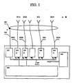
- Fig. 1 shows a typical base station structure of wireless communication system, which uses method and device of the invention for mobile communication system or wireless user loop system, etc., with smart antenna.
- the base station structure except calibration part is similar with the base station structure introduced by Chinese patent named "Time Division Duplex Synchronous Code Division Multiple Access Wireless Communication System with Smart Antenna" ( CN 97 1 04039.7 ). It mainly includes N numbers of identical antenna unit 201A, 201B, ..., 201N; N numbers of almost identical feeder cable 202A, 202B, ..., 202N; N numbers of radio frequency transceiver 203A, 203B, ..., 203N and a baseband processor 204.
- radio frequency transceivers 203 there are Analog-to-Digital Converter (ADC) and Digital-to-Analog Converter (DAC), so input and output baseband signals of all radio frequency transceiver are all digital signal; they are connected with baseband processor 204 by a high speed digital bus 209; they use a same local oscillator 208 to guarantee that each radio frequency transceiver works in coherence.
- ADC Analog-to-Digital Converter
- DAC Digital-to-Analog Converter
- a calibration link consists of coupling structure 205 (coupling radio frequency circuit), feeder cable 206 and pilot transceiver 207 is added according to different antenna array;
- coupling structure 205 is coupled with N feeder cables 202A, 202B, ..., 202N; feeder cable 206 is used for connecting coupling structure 205 and pilot transceiver 207; pilot transceiver 207 is connected with high speed digital bus 209, and uses a same local oscillator 208 with all radio frequency transceiver 203.
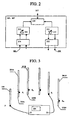
- Fig. 2 it shows structure of radio frequency transceiver 203 or pilot transceiver 207 shown in Fig. 1 .
- It includes duplexer 210, analog receiver 211, analog-to-digital converter 212, analog transmitter 213 and digital-to-analog converter 214.
- analog receiver 211 a variable gain amplifier 215 (can be controlled by software), used to control its gain, is set.
- analog transmitter 213, a variable gain amplifier 216 (can be controlled by software), used to control its gain, is set.
- Radio frequency interface 217 of duplexer 210 is connected to feeder cable 202 and 206 directly.
- Analog-to-digital converter 212 and digital-to-analog converter 214 are connected with baseband processor 204 through high speed digital bus 209.
- calibrating smart antenna system is to get transmission coefficient amplitude and phase difference between other link and the reference link on set working carrier frequency, during receiving and transmitting; therefore, in the invention, calibration of smart antenna is whole system calibration including antenna feeder cable and analog transceiver.
- Calibration work of the invention is to get, with real-time measure, difference between i th link transmission coefficient R i , T i , representing receiving and transmitting respectively, and transmission coefficient of reference link.
- Pilot antenna 230 is an antenna, which has relatively fixed physical position with the antenna array to be calibrated, the pilot antenna 230 must be in working main lobe of antenna unit radiation directivity diagram of antenna array.
- pilot antenna can be set at any position including near field region of antenna unit.
- the calibration method is: connect a Vector Network Analyzer 231 with pilot signal feed line terminal D of pilot antenna 230 and antenna terminal E i of i th link to be calibrated; at the same time, other antenna terminals of the antenna array to be calibrated such as E 1 , E 2 , ..., E N is connected to matched load 232A, 232B, ..., 232N respectively; then measure transmission coefficient C 1 of i th link to be calibrated with the vector network analyzer 231, after N numbers of measuring, transmission coefficients C 1 , ..., C i , ..., C N of all link are got.
- pilot antenna should be set at far-field region of to be calibrated smart antenna array's working range, in order to guarantee calibration accuracy, it is very difficult to implement in practice. Therefore, only when antenna unit is an omni-directional antenna, pilot antenna is set at its near field region and its far-field region characteristic is replaced by its near field region characteristic, then calibration is practicable. For example, when using ring antenna array, pilot antenna can be set at the center of this ring antenna array, with its geometric symmetry to guarantee reliability of its near field region measure.
- FIG. 4 it shows coupling structure of passive network 240, consisted of distributor/combiner and coupler, and its connection with smart antenna array 201A, 201B, ..., 201N.
- the coupling structure includes N couplers 242A, 242B, ..., 242N corresponding with N antennas 201, and a 1 : N passive distributor/combiner 241; each coupler of 242 is located at connection point E 1 , E 2 , ..., E N between each antenna unit 201A, 201B, ..., 201N and its feeder cable 202A, 202B, ..., 202N.
- the coupling structure has been independently calibrated before it is mounted in antenna array.
- the calibration method when applying coupling structure shown in Fig. 4 , the calibration method is: connect a vector network analyzer 231 with pilot signal feed line terminal D of pilot antenna 230 and antenna terminal E i of i th link to be calibrated, at the same time, other antenna terminals of the antenna array to be calibrated such as E 1 , E 2 , ..., E N is connected to matched load 232A, 232B, ..., 232N respectively; then measure transmission coefficient C i of i th link to be calibrated with the vector network analyzer 231, after N numbers of measuring, transmission coefficients C 1 , ..., C i , ..., C N of all link are got.
- Calibration method shown in Fig. 5 is same as calibration method shown in Fig. 3 .
- Passive network coupling structure shown in Fig. 4
- Passive network coupling structure is more complex than pilot antenna coupling structure, shown in Fig. 3 , and non-consistency of each antenna unit cannot be considered during calibration, but it can be conveniently used in calibration of any kind of smart antenna array.
- Fig. 6 it shows calibration procedure with coupling structure
- this calibration method can be used for both coupling structures shown in Fig. 3 and Fig. 4 .
- Coupling structure has been calibrated before smart antenna array is put into operation, the got transmission coefficient C is kept in base station.
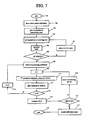
- Fig. 7 it shows whole procedure of smart antenna array calibration, before smart antenna array is put into operation, its coupling structure has been calibrated according to procedure shown in Fig. 6 , and the got receiving and transmitting transmission coefficient C has been kept in base station, where the coupling structure is located.
- Step 702 make receiving calibration first; step 703, transmitter of pilot transceiver transmits a defined voltage level signal with set working carrier frequency, in order to sure that receiving system of base station to be calibrated is working at normal working voltage level; step 704, all transceivers in receiving system of base station to be calibrated are at receiving state, i.e., N links are all at receiving state; step 705, each receiving link output is detected by baseband processor to make sure that system is working at set receiving level and each receiver is working at linearity region, according to output of each link receiver and formula (8) baseband processor calculates R i / R 1 ; steps 706 and 707, according to calculated R i / R 1 , by controlling variable gain amplifier (213 and 216 in Fig.
- step 708 when
- 1, shift to transmitting calibration; steps 709 to 715, when calibrating N transmitting links, receiver of pilot transceiver receives, respectively, signals coming from each transmitting link at set working carrier frequency; at this time among N transmitting links, said above, only one link is in transmitting state at one time and all others are in closing state (step 710); therefore, in each time, pilot receiver only receives signal coming from this link; right now, reference transmitting link must be measured and calibrated beforehand in order to make sure that its transmitting power is in rated voltage level; under this condition, receiver of pilot transceiver receives signal coming from every transmitting link (step 711); then baseband processor processes measured result and calculate T i / T 1 with formula (9) (step 714);
- Base station structure of wireless communication shown in Fig. 1 , is an example of TDD wireless communication system, but it can also be used in FDD wireless communication system.
- Any technician whose career is research and development of wireless communication system, can implement smart antenna real-time calibration, after understanding smart antenna basic principle and referring to method and device of the invention.
Landscapes
- Engineering & Computer Science (AREA)
- Computer Networks & Wireless Communication (AREA)
- Variable-Direction Aerials And Aerial Arrays (AREA)
- Radio Transmission System (AREA)
- Details Of Aerials (AREA)
- Mobile Radio Communication Systems (AREA)
Abstract
Description
- The present invention relates generally to a smart antenna technology of wireless communication system, and more particularly to a method for calibrating smart antenna array, as well as to a device for calibrating smart antenna array.
- In modern wireless communication system, especially in CDMA wireless communication system, in order to raise system capacity, to raise system sensitivity and to have farther communication distance with lower emission power, smart antenna is used, in general.
- In the Chinese patent named "Time Division Duplex Synchronous Code Division Multiple Access Wireless Communication System with Smart Antenna" (
CN 97 1 04039.7 ), a base station structure of wireless communication system with smart antenna is disclosed. It includes antenna array consisted of one or plural antenna units, corresponding radio frequency feeder cables and a set of coherent radio frequency transceivers. According to different response of each antenna unit in antenna array to signal received from user terminal, baseband processor gets space characteristic vector and direction of arrival (DOA) of the signal; then with correspondence algorithm, receiving antenna beam forming is implemented. Among them, any one of antenna unit, corresponding feeder cable and coherent radio frequency transceiver together is called a link. By using weight, which is got from up link receiving beam forming of each link, for down link transmitting beam forming, whole functionality of smart antenna can be implemented, under symmetrical radio wave propagation. - In the above Chinese patent, in order to make smart antenna combine receiving and transmitting beam accurately, the difference between each antenna unit, comprised the smart antenna array, radio frequency feeder cable and radio frequency transceiver should be known, i.e. difference of amplitude and phase variation after radio frequency signal passing each link should be known; and procedure of getting difference among links of the smart antenna system is just the one concerned by smart antenna calibration of the invention.
- Calibration of smart antenna array is a kernel technology of smart antenna, as characteristic of electronic elements, which comprise radio frequency system of smart antenna, especially active elements characteristic, is very sensitive to working frequency, environment temperature and working duration etc., characteristic variation of each link, caused by the reasons said above, is impossible the same, so calibrating smart antenna system must be taken at any time.
- In present, there are about two kinds of calibration method for smart antenna. One is direct measure method: measuring every set of radio frequency transceiver and getting data related to its amplitude and phase, then adding measured amplitude and phase characteristic of antenna unit and feeder cable to form a set of calibration data; calibration procedure of this method is very complicated, it is difficult to take all measure in field, especially for wireless communication systems have been putting into operation. Another method is calibrated by a pilot transceiver at antenna far-field region, but this method requires the pilot transceiver is located at far-field region without multipath propagation; this is also difficult to implement in practice. Therefore, disadvantage of these two methods said above is obvious.
-
US-A-5 546 090 provides a method of calibrating an antenna array system. A calibration processor generates a calibration transmit signal and transmits it through a transmit signal processor and antenna array. A transponder receives the calibration transmit signal and retransmits a transponder signal back to the antenna array. The calibration processor acquires the transponder signal through the antenna array and a receive signal processor, and processes the received signals to calculate antenna calibration vector. -
WO 95 34103 A -
WO 97 44920 A -
EP-A-0 415 574 provides an apparatus for calibrating a transmit antenna array, particularly for phasing antenna arrays. The apparatus includes two or more probe antennas, and means for determining the location of a phase centre of one of the antennas of the array from the phase at the probe antennas of a signal transmitted by that antenna of the array. The determining means compares the phase of a signal received at a probe antenna relative to that of the transmitter with the phase the probe antenna relative to that of the respective dipole which would be expected from geometrical considerations. The means derive an error signal from the actual and expected relative phases and adjust a phase shifter connected to that antenna in dependence on the error signal. - Therefore, an object of the invention is to provide a method and device for calibrating smart antenna array in real-time, thus smart antenna system is practicable; device of the invention is to make method of the invention work effectively.
- A further object of the invention is to provide two design and calibration method of couple structure for calibrating smart antenna array, which make method of invention work effectively.
- A method of the invention for calibrating smart antenna array comprising N links, each link comprising an antenna unit and a radio frequency transceiver connected via a feeder cable and one of the N links be selected as a reference link, comprises:
- 1. setting a calibration link consisted in connection of a coupling structure, a feeder cable and a pilot transceiver; the coupling structure is coupled with N antenna units of the smart antenna array and the pilot transceiver is connected to a baseband processor of a base station by a digital bus;
- 2. calibrating the coupling structure with a vector network analyzer before the smart antenna array is put into operation, recording its receiving transmission coefficient and its transmitting transmission coefficient respectively;
- 3. calibrating the N links as receiving links: transmitting a defined voltage level signal at a set working carrier frequency by analog transmitter of the pilot transceiver, and making N receiving links, in calibrated base station, are put in receiving state; detecting output of each receiving link respectively by baseband processor in base station and calculating the ratio of transmission coefficient of each receiving link to transmission coefficient of the reference link during receiving, according to the output of each receiving link; controlling the output of each receiving link by controlling variable gain amplifier, in an analogy receiver of each link, to make amplitude of ratio of transmission coefficient of each transmitting link to transmission coeffecient of the reference link equal to 1; recording and storing phase difference Φ between each receiving link and reference link in baseband processor;
- 4. calibrating the N links as transmitting links: making each transmitting link be in transmitting state and all other N-1 transmitting links are in closing state, and receiving signals coming from each transmitting link respectively at set working carrier frequency by analog receiver, in the pilot transceiver; processing detected the signals by baseband processor of base station and calculating ratio of transmission coefficient of each transmitting link to transmission coefficient of the reference link during transmitting; controlling output of each transmitting link by controlling variable gain amplifier, in each link analog transmitter, to make amplitude of the ratio of transmission coefficient of each transmitting link to transmission coefficient of the reference link equal to 1, during transmitting; recording and storing phase difference ψ between each transmitting link and reference link in baseband processor.
- Said calibrating coupling structure using the vector network analyzer comprises: setting a pilot antenna in spatial coupling mode; connecting said vector network analyzer to a feed line terminal of the pilot signal and antenna unit terminal of a link to be calibrated, connecting an antenna unit terminal of non-calibrated link to a matched load, measuring and recording the receiving and transmitting transmission coefficient the link to be calibrated under each necessary working carrier frequency; repeating said above steps until all receiving and transmitting transmission coefficients of N links have been measured and recorded.
- Said calibrating coupling structure using the vector network analyzer further comprises: setting a passive network coupling structure consisted of N couplers and a 1:N passive distributor/combiner connected with the N couplers, the N couplers are connected with an antenna terminal of the N antenna units of the smart antenna array respectively, and the output of the passive distributor/combiner is a feed line terminal of a pilot signal; connecting said vector network analyzer to the feed line terminal of the pilot signal and an antenna unit terminal of the link to be calibrated, connecting antenna unit terminal of non-calibrated link with a matched load, measuring and recording the receiving transmission coefficient and transmitting transmission coefficient of the link to be calibrated under each necessary working carrier frequency; repeating said above steps until all receiving transmission coefficient and transmitting transmission coefficients of N links have been measured and recorded.
- A device of the invention for calibrating smart antenna array comprising N links, each link comprising an antenna unit and a radio frequency transceiver connected via a feeder cable, and one of the N links being selected as a reference link, comprises:
- a calibration link located in near field of a smart antenna array to be calibrated, which comprises: a coupling structure having been calibrated, a feeder cable and a pilot transceiver; the coupling structure is coupled with N antenna units of the smart antenna array, the feeder cable is connected with the coupling structure and the pilot transceiver the pilot transceiver is connected to a baseband processor in a base station by a digital bus; and
- when the N links as receiving links are calibrated, the calibration link transmits a calibrating signal, the N receiving links receive the calibrating signal; the baseband processor is used for calculating the ratio of the transmission coefficient of each receiving link to the transmission coefficient of the reference link and getting the phase difference Φ between each receiving link and the reference link;
- when the N links as transmitting links are calibrated, each transmitting link transmits a calibrating signal, respectively, the calibration link receives the signal; the baseband processor is further used for calculating the ratio of the transmission coefficient of each link to the transmission coefficient of the reference link and getting the phase difference Φ between each transmitting link and the reference link.
- Said coupling structure is a pilot antenna with spatial coupling mode, the pilot antenna is in working main lobe of radiation directivity diagram of the N antenna units, which compose the smart antenna array; antenna terminal of the pilot antenna is a feed line terminal of a pilot signal.
- When the N antenna units, which compose the smart antenna array, are omni-directional antenna, said pilot antenna is located at any position of a near field region of each antenna unit.
- Said coupling structure is a passive network includes N couplers, corresponding with the N antenna units of said smart antenna array, and a 1:N passive distributor/combiner connected with the N couplers; said N couplers are connected with antenna terminals of the N antenna units respectively, output of said passive distributor/combiner is a feed line terminal of a pilot signal.
- Said pilot transceiver has a same structure as the radio frequency transceiver of base station, including a duplexer, a analog receiver connected with the duplexer, a analog transmitter connected with the duplexer, an analog-to-digital converter connected with the an analog receiver and a digital-to-analog converter connected with the analog transmitter; a radio frequency interface of said duplexer is connected with feeder cable of the coupling structure, said analog-to-digital converter and digital-to-analog converter are connected to said digital bus.
- In said analog receiver, a variable gain amplifier, controlled by software, is set for controlling gain; said analog transmitter comprises a variable gain amplifier, controlled by software, which is set for controlling gain.
- The invention provides a method and device of smart antenna array calibration, comprising using pilot transceiver and a set of coupling structure coupled with smart antenna array, wherein the coupling structure includes two technical schemes: one uses a method of calibrating smart antenna system by a geometrical symmetric structure pilot antenna, located at near field region or far-field region, and a antenna array implementing the method, wherein the pilot antenna and related calibrating software is a composed part of wireless base station; another one uses a passive network consisted of couplers and distributor/combiner to implement the coupling structure feeds and calibrates smart antenna array. Either of two technical schemes makes a base station with smart antenna be calibrated very easily at all times, makes radio frequency parts and elements be changed at all times, therefore, engineering practical problem of smart antenna system is solved thoroughly.
- Method and device of the invention for calibrating smart antenna array mainly point to CDMA wireless communication system, but after simple changes the proposed method and device can also be used for calibrating smart antenna of FDMA and TDMA wireless communication system.
-
-
Figure 1 is a principle diagram of wireless communication base station using method and device of the invention. -
Figure 2 is a principle diagram of analog transceiver. -
Figure 3 is a coupling structure diagram using pilot antenna. -
Figure 4 is a connection diagram of coupling structure, in smart antenna array, consisted of distributor/combiner and coupler. -
Figure 5 is another coupling structure of the invention. -
Figure 6 is flowchart of coupling structure calibration procedure. -
Figure 7 is flowchart of smart antenna calibration procedure. - With embodiment and drawings, method and device of the invention is described in detail in the following.
- Referring to
Fig. 1 , it shows a typical base station structure of wireless communication system, which uses method and device of the invention for mobile communication system or wireless user loop system, etc., with smart antenna. The base station structure except calibration part is similar with the base station structure introduced by Chinese patent named "Time Division Duplex Synchronous Code Division Multiple Access Wireless Communication System with Smart Antenna" (CN 97 1 04039.7 ). It mainly includes N numbers ofidentical antenna unit identical feeder cable baseband processor 204. In allradio frequency transceivers 203, there are Analog-to-Digital Converter (ADC) and Digital-to-Analog Converter (DAC), so input and output baseband signals of all radio frequency transceiver are all digital signal; they are connected withbaseband processor 204 by a high speeddigital bus 209; they use a samelocal oscillator 208 to guarantee that each radio frequency transceiver works in coherence. - In order to implement smart antenna real-time calibration, based on this station structure, a calibration link consists of coupling structure 205 (coupling radio frequency circuit),
feeder cable 206 andpilot transceiver 207 is added according to different antenna array; -
coupling structure 205 is coupled withN feeder cables feeder cable 206 is used for connectingcoupling structure 205 andpilot transceiver 207;pilot transceiver 207 is connected with high speeddigital bus 209, and uses a samelocal oscillator 208 with allradio frequency transceiver 203. - Referring to
Fig. 2 , it shows structure ofradio frequency transceiver 203 orpilot transceiver 207 shown inFig. 1 . It includesduplexer 210,analog receiver 211, analog-to-digital converter 212,analog transmitter 213 and digital-to-analog converter 214. Inanalog receiver 211, a variable gain amplifier 215 (can be controlled by software), used to control its gain, is set. Inanalog transmitter 213, a variable gain amplifier 216 (can be controlled by software), used to control its gain, is set.Radio frequency interface 217 ofduplexer 210 is connected tofeeder cable 202 and 206 directly. Analog-to-digital converter 212 and digital-to-analog converter 214 are connected withbaseband processor 204 through high speeddigital bus 209. - In smart antenna system, which uses base station structure shown in
Fig. 1 , there are N transmitting and receiving links in total; anyone of them is consisted of connecting antenna unit (201A, 201B, ..., 201N), feeder cable (202A, 202B, ..., 202N) and radio frequency transceiver (203A, 203B, ..., 203N), besides there is a calibration link consisted ofpilot transceiver 207 and corresponding coupling structure (205 and 206). - Suppose taking Ath link as reference link (any link can be selected as reference link), then calibrating smart antenna system is to get transmission coefficient amplitude and phase difference between other link and the reference link on set working carrier frequency, during receiving and transmitting; therefore, in the invention, calibration of smart antenna is whole system calibration including antenna feeder cable and analog transceiver.
- Suppose taking point A at antenna far-field region in
Fig. 1 , and Bi, which is a baseband interface among BA, BB, ..., Bi, ..., BN oftransceiver 203 in base station, as observation reference point, transmission characteristic of smart antenna is represented with following formulas:

where i = 1, 2, ..., N represent first to Nth link respectively; in formula (1), Ari represents ith link receiving signal at Bi point during point A emission, Sri represents degradation of ith link reception by spatial propagation, R¡ represents transmission coefficient when ith link reception and br represents point A transmitting signal when reception; in formula (2), Bti represents received signal, at receiving point A, coming from ith link, when point Bi emission, Sti represents degradation of ith link transmitting by spatial propagation, Ti represents transmission coefficient when ith link emission and at represents point Bi transmitting signal when emission. Both transmitting signal br and at, in two formulas respectively, are all digital signals, they should keep unchanged during calibration. - Calibration work of the invention is to get, with real-time measure, difference between ith link transmission coefficient Ri, Ti, representing receiving and transmitting respectively, and transmission coefficient of reference link.
- Basic means of the invention implementation is to move reference point A, said above, into antenna array, i.e., output terminal point C of
feeder cable 206 inFig. 1 , by settingpilot transceiver 207,related feeder cable 206 andcoupling structure 205; thus formulas (1) and (2) are rewritten respectively:

where i = 1, 2, ..., N represent first to Nth link respectively; in formula (3), ACri represents ith link receiving signal at point Bi when point C emission, Cri represents transmission coefficient of the coupling structure when receiving test to ith link; in formula (4), BCti represents receiving point C receives signal, coming from ith link, when point Bi emission, Cti represents transmission coefficient of the coupling structure when transmitting test to ith link. - If coupling structure is designed as a passive network, then this coupling structure has interchangeability, i.e.:

- Replacing formula (5) into formulas (3) and (4), then following formulas can be got:


- In the invention, any link can be set as a reference link, suppose 1 link is set as reference link, then formulas (6) and (7) are changed to following formulas:


where i = 2, 3, ..., N represent second to Nth link, all of ACr1, BCt1, ACr¡ and BOti can be measured in real-time, C1 and Ci can be calibrated beforehand and is defined by coupling structure, so Ri R1 and Ti / T1 needed for smart antenna system calibration can be simply calculated. - Referring to
Fig. 3 , it shows a coupling structure of the invention, i.e., spatial coupling mode structure applying pilot antenna.Pilot antenna 230 is an antenna, which has relatively fixed physical position with the antenna array to be calibrated, thepilot antenna 230 must be in working main lobe of antenna unit radiation directivity diagram of antenna array. When each antenna unit is omni-directional antenna, pilot antenna can be set at any position including near field region of antenna unit. - Applying this coupling structure, the calibration method is: connect a
Vector Network Analyzer 231 with pilot signal feed line terminal D ofpilot antenna 230 and antenna terminal Ei of ith link to be calibrated; at the same time, other antenna terminals of the antenna array to be calibrated such as E1, E2, ..., EN is connected to matchedload vector network analyzer 231, after N numbers of measuring, transmission coefficients C1, ..., Ci, ..., CN of all link are got. - Advantage of this coupling structure is simple, when calibrating, non-consistency of every antenna unit has been considered; disadvantage of this coupling structure is position of pilot antenna is limited. Because pilot antenna should be set at far-field region of to be calibrated smart antenna array's working range, in order to guarantee calibration accuracy, it is very difficult to implement in practice. Therefore, only when antenna unit is an omni-directional antenna, pilot antenna is set at its near field region and its far-field region characteristic is replaced by its near field region characteristic, then calibration is practicable. For example, when using ring antenna array, pilot antenna can be set at the center of this ring antenna array, with its geometric symmetry to guarantee reliability of its near field region measure.
- Referring to
Fig. 4 , it shows coupling structure ofpassive network 240, consisted of distributor/combiner and coupler, and its connection withsmart antenna array N couplers combiner 241; each coupler of 242 is located at connection point E1, E2, ..., EN between eachantenna unit feeder cable - Referring to
Fig.5 , when applying coupling structure shown inFig. 4 , the calibration method is: connect avector network analyzer 231 with pilot signal feed line terminal D ofpilot antenna 230 and antenna terminal Ei of ith link to be calibrated, at the same time, other antenna terminals of the antenna array to be calibrated such as E1, E2, ..., EN is connected to matchedload vector network analyzer 231, after N numbers of measuring, transmission coefficients C1, ..., Ci, ..., CN of all link are got. Calibration method shown inFig. 5 is same as calibration method shown inFig. 3 . - Passive network coupling structure, shown in
Fig. 4 , is more complex than pilot antenna coupling structure, shown inFig. 3 , and non-consistency of each antenna unit cannot be considered during calibration, but it can be conveniently used in calibration of any kind of smart antenna array. - Referring to
Fig. 6 , it shows calibration procedure with coupling structure, this calibration method can be used for both coupling structures shown inFig. 3 andFig. 4 . Coupling structure has been calibrated before smart antenna array is put into operation, the got transmission coefficient C is kept in base station. -
Step 601, calibration starts;step 602, calibrate first link of N links, i.e., i = 1;step 603, with connection mode shown inFig. 3 orFig. 5 , calibrate first link;step 604, set first calibration frequency equals to first working carrier frequency of J working carrier frequencies, i.e., j = 1;step 605, set first link working carrier frequency equals to the first working carrier frequency;step 606, with vector network analyzer, measure transmission coefficient Ci of first link when calibration frequency equals to first working carrier frequency;step 607, record this measuring result;steps steps - Measure each link at each necessary carrier frequency and record all measuring results, then calibration of coupling structure is completed and whole transmission coefficients C is got.
- Referring to
Fig. 7 , it shows whole procedure of smart antenna array calibration, before smart antenna array is put into operation, its coupling structure has been calibrated according to procedure shown inFig. 6 , and the got receiving and transmitting transmission coefficient C has been kept in base station, where the coupling structure is located. - Step 702, make receiving calibration first; step 703, transmitter of pilot transceiver transmits a defined voltage level signal with set working carrier frequency, in order to sure that receiving system of base station to be calibrated is working at normal working voltage level; step 704, all transceivers in receiving system of base station to be calibrated are at receiving state, i.e., N links are all at receiving state; step 705, each receiving link output is detected by baseband processor to make sure that system is working at set receiving level and each receiver is working at linearity region, according to output of each link receiver and formula (8) baseband processor calculates Ri / R1; steps 706 and 707, according to calculated Ri / R1, by controlling variable gain amplifier (213 and 216 in
Fig. 2 ) in each receiver, output of each receiving link is controlled until |Ri / R1| = 1; record and store phase difference Φi, between each receiving link and reference link, in baseband processor, which will be used by smart antenna when working; step 708, when |Ri / R1| = 1, shift to transmitting calibration; steps 709 to 715, when calibrating N transmitting links, receiver of pilot transceiver receives, respectively, signals coming from each transmitting link at set working carrier frequency; at this time among N transmitting links, said above, only one link is in transmitting state at one time and all others are in closing state (step 710); therefore, in each time, pilot receiver only receives signal coming from this link; right now, reference transmitting link must be measured and calibrated beforehand in order to make sure that its transmitting power is in rated voltage level; under this condition, receiver of pilot transceiver receives signal coming from every transmitting link (step 711); then baseband processor processes measured result and calculate Ti / T1 with formula (9) (step 714); after that, according to this value, output of each transmitting link is controlled by variable gain amplifier (211 and 215 inFig. 2 ) of each transmitter until |Ti / T1| = 1 for each transmitting link (step 716); at the same time, phase difference Ψi between each transmitting link and reference link is recorded in baseband processor, up to now real-time calibration of smart antenna is completed. - Although method and device of the invention are proposed pointing to CDMA wireless communication system, but after simple changes, they can be used in FDMA and TDMA wireless communication system. Base station structure of wireless communication, shown in
Fig. 1 , is an example of TDD wireless communication system, but it can also be used in FDD wireless communication system. Any technician, whose career is research and development of wireless communication system, can implement smart antenna real-time calibration, after understanding smart antenna basic principle and referring to method and device of the invention.
Claims (14)
- A method for calibrating a smart antenna array comprising N links, wherein each link comprises an antenna unit (201) and a radio frequency transceiver (203) connected via a feeder cable (202), and one of the N links is selected as a reference link, the method comprising:1) setting a calibration link comprising a coupling structure (205), a feeder cable (206) and a pilot transceiver (207), wherein the coupling structure(205) is coupled with N antenna units of the smart antenna array and the pilot transceiver (207) is connected to a baseband processor (204) of a base station by a digital bus (209);2) calibrating the coupling structure (205) before the smart antenna array is put into operation respectively, recording its receiving transmission coefficient and its transmitting transmission coefficient;3) calibrating the N links as receiving links by transmitting a defined voltage level signal at a set working carrier frequency by the pilot transceiver (207), receiving the defined voltage level signal by the N receiving links; equalizing the amplitude of a transmission coefficient of each receiving link with the amplitude of a transmission coefficient of the reference link and obtaining a phase difference Φ between each receiving link-and the reference link by using the recorded receiving transmission coefficient of the coupling structure and the defined voltage level signals received by the receiving link and the reference link;4) calibrating the N links as transmitting links by putting each transmitting link in a transmitting state and the other N-1 transmitting links in a closing state to transmit signals from each of the N transmitting links, and receiving signals coming from the N transmitting links at the set working carrier frequency by the pilot transceiver (207); equalizing the amplitude of transmission coefficient of each transmitting link with amplitude of transmission coefficient of the reference link and obtaining a phase difference ψ between each N transmitting link and the reference link by using the recorded transmitting transmission coefficient of the coupling structure and the signals coming from the reference link and the transmitting link received by the pilot transceiver (207).
- A method for calibrating a smart antenna array according to claim 1, wherein it is characterized that: said calibrating the coupling structure (205) is performed by using a vector network analyzer.
- A method for calibrating a smart antenna array according to claim 2, wherein it is characterized that said calibrating the coupling structure(205) using the vector network analyzer comprises:setting a pilot antenna (230) in spatial coupling mode;connecting said vector network analyzer to a feed line terminal of the pilot signal and antenna unit terminal of a link to be calibrated,connecting an antenna unit terminal of non-calibrated link to a matched load,measuring and recording the receiving and transmitting transmission coefficient of the link to be calibrated under each necessary working carrier frequency;andrepeating said above steps until all receiving and transmitting transmission coefficients of N links have been measured and recorded.
- A method for calibrating a smart antenna array according to claim 3, wherein it is characterized that: said pilot antenna is in a working main lobe of a radiation directivity diagram of N antenna units, which compose the smart antenna array; and an antenna terminal of the pilot antenna (230) is the feed line terminal of the pilot signal.
- A method for calibrating a smart antenna array according to claim 3, wherein it is characterized that: when the N antenna units, which compose the smart antenna array, are omni-directional antenna, said pilot antenna (230) is located at any position of a near field region of each antenna unit.
- A method for calibrating a smart antenna array according to claim 1, wherein it is characterized that said equalizing the amplitude of transmission coefficient of each receiving link with amplitude of transmission coefficient of the reference link comprises:detecting output of each receiving link respectively by the baseband processor in the base station and calculating the ratio of the transmission coefficient of each transmitting link to the transmission coefficient of the reference link during receiving, according to the output of each receiving link;controlling the output of each receiving link by controlling a variable gain amplifier, in an analogy receiver in each link, to make the amplitude of the ratio of transmission coefficient of each receiving link to the transmission coefficient of the reference link during receiving equal to 1; andthe method comprises: recording and storing phase difference Φ between each receiving link and reference link in baseband processor.
- A method for calibrating a smart antenna array according to claim 1, wherein it is characterized that said equalizing the amplitude of the transmission coefficient of each transmitting link with amplitude of the transmission coefficient of the reference link comprises:processing detected signals by the baseband processor of the base station and calculating the ratio of the transmission coefficient of each transmitting link to the transmission coefficient of the reference link during transmitting;controlling the output of each transmitting link by controlling a variable gain amplifier, in an analog transmitter in each link, to make amplitude of ratio of the transmission coefficient of each link to the transmission coefficient of the reference link during transmitting equal to 1, during transmitting; andthe method comprises: recording and storing phase difference Ψ between each transmitting link and reference link in baseband processor.
- A method for calibrating a smart antenna array according to claim 2, wherein it is characterized that said calibrating the coupling structure using the vector network analyzer comprises:setting a passive network coupling structure consisted of N couplers and a 1:N passive distributor/combiner connected with the N couplers, wherein the N couplers are connected with an antenna terminal of the N antenna units of the smart antenna array respectively, and the output of the passive distributor/combiner is a feed line terminal of a pilot signal;connecting said vector network analyzer to the feed line terminal of the pilot signal and an antenna unit terminal of the link to be calibrated,connecting an antenna unit terminal of non-calibrated link with a matched load,measuring and recording the receiving transmission coefficient and transmitting transmission coefficient of the link to be calibrated under each necessary working carrier frequency;repeating said above steps until all receiving transmission coefficient and transmitting transmission coefficients of N links have been measured and recorded.
- A device for calibrating a smart antenna array comprising N links, wherein each link comprising an antenna unit (201) and a radio frequency transceiver (203) connected via a feeder cable (202), and one of the N links is selected as a reference link, the device comprising:a calibration link located in near field of a smart antenna array to be calibrated, which comprises: a coupling structure (205) having been calibrated, a feeder cable (206) and a pilot transceiver (207); wherein the coupling structure (205) is coupled with N antenna units (201) of the smart antenna array, the feeder cable (206) is connected with the coupling structure (205) and the pilot transceiver (207), the pilot transceiver (207) is connected to a baseband processor (204) in a base station by a digital bus (209);when the N links as receiving links are calibrated, the calibration link transmits a calibrating signal, the N receiving links receive the calibrating signal; the baseband processor is used for calculating the ratio of the transmission coefficient of each receiving link to the transmission coefficient of the reference link and getting the phase difference Φ between each receiving link and the reference link;when the N links as transmitting links are calibrated, each transmitting link transmits a calibrating signal, respectively, the calibration link receives the signal; the baseband processor is further used for calculating the ratio of the transmission coefficient of each link to the transmission coefficient of the reference link and getting the phase difference Φ between each transmitting link and the reference link.
- A device for calibrating a smart antenna array according to claim 9, wherein it is characterized that: said coupling structure (205) is a pilot antenna (230) in spatial coupling mode, the pilot antenna (230) is in working main lobe of radiation directivity diagram of the N antenna units (201), which compose the smart antenna array; antenna terminal of the pilot antenna (230) is a feed line terminal of a pilot signal.
- A device for calibrating a smart antenna array according to claim 10, wherein it is characterized that: when the N antenna units (201), which compose the smart antenna array, are omni-directional antenna, said pilot antenna (230) is located at any position of a near field region of each antenna unit (201).
- A device for calibrating a smart antenna array according to claim 9, wherein it is characterized that: said coupling structure (205) is a passive network including couplers (242), corresponding with the N antenna units (201) of said smart antenna array, and a 1:N passive distributor/combiner (241) connected with the N couplers (242); said N couplers(242) are connected with antenna terminal of the N antenna units (201) respectively, output of said passive distributor/combiner (241) is a feed line terminal of a pilot signal.
- A device for calibrating a smart antenna array according to claim 9, wherein it is characterized that: said pilot transceiver (207) has a same structure as the radio frequency transceiver (203) of the base station, including a duplexer (210), a analog receiver (211) connected with the duplexer (210), an analog transmitter(211) connected with the duplexer(210), an analog-to-digital converter (212) connected with the analog receiver (211) and a digital-to-analog converter (214) connected with the analog transmitter (213); a radio frequency interface (217) of said duplexer (210) is connected with the feeder cable (206) of the coupling structure, said analog-to-digital converter (212) and digital-to-analog converter (214) are connected to said digital bus (209).
- A device for calibrating a smart antenna array according to claim 13, wherein it is characterized that: in said analog receiver (211), a variable gain amplifier (215), controlled by software, is set for controlling gain; said analog transmitter (213) comprises a variable gain amplifier(216), controlled by software,which is set for controlling gain.
Applications Claiming Priority (3)
| Application Number | Priority Date | Filing Date | Title |
|---|---|---|---|
| CN99111350A CN1118146C (en) | 1999-08-10 | 1999-08-10 | Method and device for calibrating intelligent antenna array |
| CN99111350 | 1999-08-10 | ||
| PCT/CN2000/000178 WO2001011719A1 (en) | 1999-08-10 | 2000-06-26 | Method and apparatus for calibrating smart antenna array |
Publications (3)
| Publication Number | Publication Date |
|---|---|
| EP1204161A1 EP1204161A1 (en) | 2002-05-08 |
| EP1204161A4 EP1204161A4 (en) | 2005-02-09 |
| EP1204161B1 true EP1204161B1 (en) | 2008-08-20 |
Family
ID=5275033
Family Applications (1)
| Application Number | Title | Priority Date | Filing Date |
|---|---|---|---|
| EP00940116A Expired - Lifetime EP1204161B1 (en) | 1999-08-10 | 2000-06-26 | Method and apparatus for calibrating smart antenna array |
Country Status (14)
| Country | Link |
|---|---|
| US (1) | US6600445B2 (en) |
| EP (1) | EP1204161B1 (en) |
| JP (1) | JP4392476B2 (en) |
| KR (1) | KR100602055B1 (en) |
| CN (1) | CN1118146C (en) |
| AT (1) | ATE405969T1 (en) |
| AU (1) | AU777585B2 (en) |
| BR (1) | BRPI0013095B1 (en) |
| CA (1) | CA2381384C (en) |
| DE (1) | DE60039988D1 (en) |
| HK (1) | HK1034825A1 (en) |
| MX (1) | MXPA02001463A (en) |
| RU (1) | RU2265263C2 (en) |
| WO (1) | WO2001011719A1 (en) |
Cited By (1)
| Publication number | Priority date | Publication date | Assignee | Title |
|---|---|---|---|---|
| TWI451704B (en) * | 2010-03-18 | 2014-09-01 | Alcatel Lucent | Calibration of active transceiver array for wireless telecommunications network |
Families Citing this family (78)
| Publication number | Priority date | Publication date | Assignee | Title |
|---|---|---|---|---|
| DE60034210T2 (en) * | 1999-12-15 | 2007-12-20 | Nippon Telegraph And Telephone Corp. | Transceiver with adaptive array antenna |
| JP2002261668A (en) * | 2001-03-01 | 2002-09-13 | Hitachi Kokusai Electric Inc | Communication apparatus |
| US6496140B1 (en) * | 2001-03-27 | 2002-12-17 | Nokia Networks Oy | Method for calibrating a smart-antenna array radio transceiver unit and calibrating system |
| KR100428709B1 (en) * | 2001-08-17 | 2004-04-27 | 한국전자통신연구원 | Apparatus for Forward Beamforming using Feedback of Multipath Information and Method Thereof |
| GB0224341D0 (en) | 2002-10-19 | 2002-11-27 | Qinetiq Ltd | Mobile radio base station |
| US7155171B2 (en) * | 2001-12-12 | 2006-12-26 | Saraband Wireless | Vector network analyzer applique for adaptive communications in wireless networks |
| AU2002249157A1 (en) * | 2002-01-30 | 2003-09-04 | Telefonaktiebolaget L M Ericsson (Publ) | Method and system for transmission of carrier signals between first and second antenna networks |
| GB0202374D0 (en) * | 2002-02-01 | 2002-03-20 | Roke Manor Research | Antenna calibration |
| US7327800B2 (en) | 2002-05-24 | 2008-02-05 | Vecima Networks Inc. | System and method for data detection in wireless communication systems |
| FI20021094A0 (en) | 2002-06-07 | 2002-06-07 | Nokia Corp | Ensuring connection in the radio system |
| GB2390495A (en) * | 2002-07-05 | 2004-01-07 | Motorola Inc | Calibration of a transmitter or receiver in a transceiver wherein transmitter signals may be detected via the receiver or a separate detection arrangement |
| CN1170450C (en) * | 2002-09-13 | 2004-10-06 | 大唐移动通信设备有限公司 | Method for adjusting intelligences antenna array system in real time |
| JP4010225B2 (en) | 2002-10-30 | 2007-11-21 | 日本電気株式会社 | Array antenna transceiver |
| CN1176555C (en) | 2002-12-25 | 2004-11-17 | 大唐移动通信设备有限公司 | Method for adjusting intelligences antenna array system in real time |
| US7327795B2 (en) | 2003-03-31 | 2008-02-05 | Vecima Networks Inc. | System and method for wireless communication systems |
| KR100608736B1 (en) * | 2003-04-29 | 2006-08-04 | 엘지전자 주식회사 | Apparatus for generating reference signal in a smart antenna system |
| JP4326902B2 (en) * | 2003-10-15 | 2009-09-09 | Kddi株式会社 | Apparatus and method for adjusting RF circuit transmission characteristics for array antenna |
| CN1308696C (en) * | 2003-11-29 | 2007-04-04 | 富士康(昆山)电脑接插件有限公司 | Antenna testing method |
| WO2005057720A2 (en) * | 2003-12-02 | 2005-06-23 | Motia, Inc. | System and method for providing a smart antenna |
| AU2003296229A1 (en) * | 2003-12-31 | 2005-08-12 | Zte Corporation | Adjust equipment and method for array antenna transmitting link |
| EP1763150B1 (en) | 2004-05-31 | 2015-03-11 | ZTE Corporation | Calibration apparatus and method for a receiving link of array communication system |
| CN100399719C (en) * | 2005-02-03 | 2008-07-02 | 芯通科技(成都)有限公司 | Calibrating method for intelligent antenna array and radio frequency receiving-transmitting machine |
| US20060240784A1 (en) * | 2005-04-22 | 2006-10-26 | Qualcomm Incorporated | Antenna array calibration for wireless communication systems |
| US8498669B2 (en) * | 2005-06-16 | 2013-07-30 | Qualcomm Incorporated | Antenna array calibration for wireless communication systems |
| CN1913402B (en) * | 2005-08-11 | 2010-10-13 | 中兴通讯股份有限公司 | Intelligent method for detecting antenna fault |
| US9118111B2 (en) * | 2005-11-02 | 2015-08-25 | Qualcomm Incorporated | Antenna array calibration for wireless communication systems |
| US8280430B2 (en) * | 2005-11-02 | 2012-10-02 | Qualcomm Incorporated | Antenna array calibration for multi-input multi-output wireless communication systems |
| CN100445758C (en) * | 2005-12-06 | 2008-12-24 | 大唐移动通信设备有限公司 | Smart antenna testing method and system |
| US7482976B2 (en) * | 2006-04-10 | 2009-01-27 | Aviation Communication & Surveillance Systems | Antenna calibration method and apparatus |
| CN101064902B (en) * | 2006-04-25 | 2010-11-10 | 大唐移动通信设备有限公司 | Method for real-time calibrating intelligent antenna |
| DE102006045645B4 (en) | 2006-09-27 | 2015-05-07 | Rohde & Schwarz Gmbh & Co. Kg | antenna |
| CN101188448B (en) * | 2006-11-15 | 2011-09-14 | 电信科学技术研究院 | A smart antenna calibration method, device and system |
| GB2456007B (en) * | 2007-12-31 | 2012-10-17 | Nortel Networks Ltd | Method for channel calibration |
| US7843347B2 (en) * | 2008-01-30 | 2010-11-30 | Intermac Ip Corp. | Near-field and far-field antenna-assembly and devices having same |
| CN101552994B (en) * | 2008-04-02 | 2011-04-20 | 大唐移动通信设备有限公司 | Method and device for staggering receiving calibration and transmitting calibration |
| CN101588198B (en) * | 2008-05-19 | 2012-08-29 | 成都芯通科技股份有限公司 | Multi-carrier intelligent antenna calibration intermediate-frequency processing method and device |
| CN101304276B (en) * | 2008-06-30 | 2012-07-04 | 华为技术有限公司 | Method and system for transmitting channel correction |
| JP2010034937A (en) * | 2008-07-30 | 2010-02-12 | Sony Corp | Wireless communication device, wireless communication method, and computer program |
| US8193971B2 (en) * | 2008-11-10 | 2012-06-05 | Motorola Mobility, Inc. | Antenna reciprocity calibration |
| GB0823593D0 (en) * | 2008-12-30 | 2009-01-28 | Astrium Ltd | Calibration apparatus and method |
| US8219035B2 (en) | 2009-09-18 | 2012-07-10 | ReVerb Networks, Inc. | Enhanced calibration for multiple signal processing paths in a wireless network |
| US8179314B2 (en) * | 2009-10-22 | 2012-05-15 | ReVerb Networks, Inc. | Enhanced calibration for multiple signal processing paths in a frequency division duplex system |
| CN102130727A (en) * | 2010-01-19 | 2011-07-20 | 北京无线电计量测试研究所 | Method for measurement traceability of vector modulation by using special vector modulation source |
| CN102986085B (en) * | 2010-07-01 | 2015-09-30 | 诺基亚通信公司 | Antenna arrangement |
| CN102136860A (en) * | 2011-03-10 | 2011-07-27 | 西安电子科技大学 | Channel correction system and method for transmission digital beam forming technology |
| CN102149123B (en) * | 2011-04-15 | 2013-12-04 | 北京邮电大学 | Scheme and device for calibrating antennae among base stations in cooperative multi-point system and base station |
| WO2013187811A1 (en) * | 2012-06-12 | 2013-12-19 | Telefonaktiebolaget L M Ericsson (Publ) | Calibration coupleing unit, ccu, and a method therein for enabling calibration of base station |
| CN102857309B (en) | 2012-07-27 | 2016-09-28 | 中兴通讯股份有限公司 | The method of testing of a kind of radio frequency index of active antenna system and device |
| CN102830298B (en) | 2012-07-27 | 2017-04-12 | 中兴通讯股份有限公司 | Method and device for testing radio frequency index and wireless index of active antenna system |
| KR101994325B1 (en) * | 2013-05-31 | 2019-09-30 | 삼성전자주식회사 | Array antenna apparatus and control method thereof in communication system |
| GB2516617B (en) * | 2013-06-12 | 2018-02-21 | Analog Devices Global | Communication unit or method for identifying a connectivity relationship between a logical channel and an antenna element of an active antenna system |
| CN103828270B (en) * | 2013-06-27 | 2015-11-25 | 华为技术有限公司 | Based on the channel calibration method of antenna-feedback system, device and base station |
| CN106411378B (en) * | 2013-09-02 | 2019-11-29 | 华为技术有限公司 | Communication equipment, Base Band Unit and communication means |
| US9893715B2 (en) * | 2013-12-09 | 2018-02-13 | Shure Acquisition Holdings, Inc. | Adaptive self-tunable antenna system and method |
| CN103795483B (en) * | 2014-01-29 | 2016-08-17 | 浙江网新技术有限公司 | antenna transmission performance adjusting method |
| RU2584458C1 (en) * | 2014-10-17 | 2016-05-20 | Акционерное общество "Конструкторское бюро "Аметист" (АО"КБ"Аметист") | Digital scanning receiving antenna array for radar station |
| US9759799B2 (en) | 2015-06-24 | 2017-09-12 | International Business Machines Corporation | Beacon array |
| CN105244625B (en) * | 2015-10-28 | 2017-11-10 | 武汉滨湖电子有限责任公司 | A kind of C-band integration microstrip antenna |
| CN105846917A (en) * | 2016-03-16 | 2016-08-10 | 太仓市同维电子有限公司 | Calibration system and calibration method thereof based on wireless test |
| US10263330B2 (en) | 2016-05-26 | 2019-04-16 | Nokia Solutions And Networks Oy | Antenna elements and apparatus suitable for AAS calibration by selective couplerline and TRX RF subgroups |
| RU2630846C1 (en) * | 2016-06-16 | 2017-09-13 | Акционерное Общество "Нпо "Электронное Приборостроение" | Digital ring antenna array |
| US20180062260A1 (en) * | 2016-08-26 | 2018-03-01 | Analog Devices Global | Antenna array calibration systems and methods |
| EP3293897B8 (en) * | 2016-09-12 | 2020-08-12 | Rohde & Schwarz GmbH & Co. KG | System and method for characterization of multi-element antenna |
| US11177567B2 (en) * | 2018-02-23 | 2021-11-16 | Analog Devices Global Unlimited Company | Antenna array calibration systems and methods |
| US11349208B2 (en) | 2019-01-14 | 2022-05-31 | Analog Devices International Unlimited Company | Antenna apparatus with switches for antenna array calibration |
| US11404779B2 (en) | 2019-03-14 | 2022-08-02 | Analog Devices International Unlimited Company | On-chip phased array calibration systems and methods |
| US11276928B1 (en) | 2019-04-10 | 2022-03-15 | The Governors Of The University Of Alberta | Calibrating/monitoring method and apparatus for phased array antenna employing very near field |
| CN110717234A (en) * | 2019-10-17 | 2020-01-21 | 上海机电工程研究所 | Irregular layout triple angular position simulation method, system and medium |
| US11450952B2 (en) | 2020-02-26 | 2022-09-20 | Analog Devices International Unlimited Company | Beamformer automatic calibration systems and methods |
| US11611143B2 (en) | 2020-03-24 | 2023-03-21 | Commscope Technologies Llc | Base station antenna with high performance active antenna system (AAS) integrated therein |
| MX2022011871A (en) | 2020-03-24 | 2022-12-06 | Commscope Technologies Llc | Base station antennas having an active antenna module and related devices and methods. |
| CN115693182A (en) | 2020-03-24 | 2023-02-03 | 康普技术有限责任公司 | Radiating element with angled feed stalk and base station antenna including the same |
| CN111562553A (en) * | 2020-05-06 | 2020-08-21 | 中国人民解放军63892部队 | Method for improving radio frequency semi-physical simulation broadband signal angle simulation precision |
| GB202011276D0 (en) * | 2020-07-21 | 2020-09-02 | Sofant Tech Ltd | Phased array antenna apparatus and method |
| CN114531182A (en) * | 2020-11-03 | 2022-05-24 | 南京中兴新软件有限责任公司 | Array antenna calibration method, device and storage medium |
| IT202100014927A1 (en) * | 2021-06-08 | 2022-12-08 | Commscope Technologies Llc | SYSTEMS AND METHODS FOR GENERATION OF CALIBRATION DATA IN ACTIVE ANTENNA MODULES HAVING INSIDE ANTENNA-SIDE ARRAYS OF FILTERS |
| CN114584228B (en) * | 2022-05-05 | 2022-07-08 | 成都爱旗科技有限公司 | Wifi production test calibration system and method and electronic equipment |
| WO2024110018A1 (en) * | 2022-11-22 | 2024-05-30 | Huawei Technologies Co., Ltd. | Device and method for calibration of a phased array device |
Family Cites Families (4)
| Publication number | Priority date | Publication date | Assignee | Title |
|---|---|---|---|---|
| GB2236431B (en) * | 1989-08-30 | 1993-11-03 | Marconi Gec Ltd | Antenna array |
| US5546090A (en) * | 1991-12-12 | 1996-08-13 | Arraycomm, Inc. | Method and apparatus for calibrating antenna arrays |
| BR9507801A (en) * | 1994-06-03 | 1998-05-26 | Ericsson Telefon Ab L M | Process and system for calibrating the transmission and reception of an antenna array for use in a mobile radio communications system |
| GB2313523B (en) * | 1996-05-23 | 2000-06-07 | Motorola Ltd | Self-calibration apparatus and method for communication device |
-
1999
- 1999-08-10 CN CN99111350A patent/CN1118146C/en not_active Expired - Lifetime
-
2000
- 2000-06-26 AU AU55191/00A patent/AU777585B2/en not_active Expired
- 2000-06-26 EP EP00940116A patent/EP1204161B1/en not_active Expired - Lifetime
- 2000-06-26 DE DE60039988T patent/DE60039988D1/en not_active Expired - Lifetime
- 2000-06-26 KR KR1020027001460A patent/KR100602055B1/en active IP Right Grant
- 2000-06-26 WO PCT/CN2000/000178 patent/WO2001011719A1/en active IP Right Grant
- 2000-06-26 MX MXPA02001463A patent/MXPA02001463A/en active IP Right Grant
- 2000-06-26 CA CA002381384A patent/CA2381384C/en not_active Expired - Lifetime
- 2000-06-26 BR BRPI0013095-8A patent/BRPI0013095B1/en active IP Right Grant
- 2000-06-26 RU RU2002106105/09A patent/RU2265263C2/en active
- 2000-06-26 AT AT00940116T patent/ATE405969T1/en not_active IP Right Cessation
- 2000-06-26 JP JP2001516275A patent/JP4392476B2/en not_active Expired - Lifetime
-
2001
- 2001-07-27 HK HK01105234A patent/HK1034825A1/en not_active IP Right Cessation
-
2002
- 2002-02-11 US US10/073,566 patent/US6600445B2/en not_active Expired - Lifetime
Cited By (2)
| Publication number | Priority date | Publication date | Assignee | Title |
|---|---|---|---|---|
| TWI451704B (en) * | 2010-03-18 | 2014-09-01 | Alcatel Lucent | Calibration of active transceiver array for wireless telecommunications network |
| US9113346B2 (en) | 2010-03-18 | 2015-08-18 | Alcatel Lucent | Calibration |
Also Published As
| Publication number | Publication date |
|---|---|
| BRPI0013095B1 (en) | 2015-06-16 |
| US6600445B2 (en) | 2003-07-29 |
| EP1204161A4 (en) | 2005-02-09 |
| DE60039988D1 (en) | 2008-10-02 |
| CN1283901A (en) | 2001-02-14 |
| CN1118146C (en) | 2003-08-13 |
| RU2265263C2 (en) | 2005-11-27 |
| MXPA02001463A (en) | 2003-07-21 |
| WO2001011719A1 (en) | 2001-02-15 |
| AU5519100A (en) | 2001-03-05 |
| AU777585B2 (en) | 2004-10-21 |
| JP2003522445A (en) | 2003-07-22 |
| BR0013095A (en) | 2002-04-30 |
| ATE405969T1 (en) | 2008-09-15 |
| KR20020019600A (en) | 2002-03-12 |
| JP4392476B2 (en) | 2010-01-06 |
| US20020089447A1 (en) | 2002-07-11 |
| CA2381384A1 (en) | 2001-02-15 |
| HK1034825A1 (en) | 2001-11-02 |
| CA2381384C (en) | 2008-06-03 |
| KR100602055B1 (en) | 2006-07-14 |
| EP1204161A1 (en) | 2002-05-08 |
Similar Documents
| Publication | Publication Date | Title |
|---|---|---|
| EP1204161B1 (en) | Method and apparatus for calibrating smart antenna array | |
| US6400318B1 (en) | Adaptive array antenna | |
| EP1548957B1 (en) | Method for calibrating smart antenna array in real time | |
| US6339399B1 (en) | Antenna array calibration | |
| EP1585231B1 (en) | A method for calibrating smart antenna array systems in real time | |
| US6735182B1 (en) | Adaptive array antenna system | |
| US11522501B2 (en) | Phased array amplifier linearization | |
| US10797807B2 (en) | Methods for calibrating millimeter wave antenna arrays | |
| EP1438768B1 (en) | Frequency dependent calibration of a wideband radio system using narrowband channels | |
| KR100382454B1 (en) | Adaptive array antenna transmitting/receiving apparatus | |
| KR100399692B1 (en) | Radio device and method of calibration of antenna directivity | |
| US9318804B2 (en) | Method and apparatus for power loss compensation and suppression of sidelobes in antenna arrays | |
| RU2002106105A (en) | METHOD AND DEVICE FOR CALIBRATING AN INTELLIGENT ANTENNA GRILLE | |
| EP2173010A1 (en) | Improved probe calibration for an active antenna | |
| EP2173005B1 (en) | Improved probe calibration for an active antenna | |
| WO2002011237A1 (en) | Calibration apparatus and method for use with an antenna array | |
| EP1309104B1 (en) | Calibration device, adaptive array device, calibration method, program recording medium and program | |
| EP1133836B1 (en) | Method and apparatus for calibrating a wireless communications station having an antenna array | |
| CN114389039A (en) | Method for calibrating relative phase from transmitter to receiver and millimeter wave antenna module | |
| US20040048580A1 (en) | Base transceiver station | |
| EP1271802A1 (en) | A system and a method for calibrating radio frequency transceiver systems including antenna arrays | |
| US6229483B1 (en) | Method and device relating to self-calibration of group antenna system having time varying transmission characteristics | |
| CN111869128A (en) | Radio communication system, radio communication device, radio communication method, and non-transitory computer-readable medium |
Legal Events
| Date | Code | Title | Description |
|---|---|---|---|
| PUAI | Public reference made under article 153(3) epc to a published international application that has entered the european phase |
Free format text: ORIGINAL CODE: 0009012 |
|
| 17P | Request for examination filed |
Effective date: 20011126 |
|
| AK | Designated contracting states |
Kind code of ref document: A1 Designated state(s): AT BE CH CY DE DK ES FI FR GB GR IE IT LI LU MC NL PT SE |
|
| AX | Request for extension of the european patent |
Free format text: AL;LT;LV;MK;RO;SI |
|
| A4 | Supplementary search report drawn up and despatched |
Effective date: 20041229 |
|
| RIC1 | Information provided on ipc code assigned before grant |
Ipc: 7H 01Q 1/24 B Ipc: 7H 01Q 3/26 A |
|
| 17Q | First examination report despatched |
Effective date: 20070516 |
|
| GRAP | Despatch of communication of intention to grant a patent |
Free format text: ORIGINAL CODE: EPIDOSNIGR1 |
|
| GRAS | Grant fee paid |
Free format text: ORIGINAL CODE: EPIDOSNIGR3 |
|
| GRAA | (expected) grant |
Free format text: ORIGINAL CODE: 0009210 |
|
| AK | Designated contracting states |
Kind code of ref document: B1 Designated state(s): AT BE CH CY DE DK ES FI FR GB GR IE IT LI LU MC NL PT SE |
|
| REG | Reference to a national code |
Ref country code: GB Ref legal event code: FG4D |
|
| REG | Reference to a national code |
Ref country code: CH Ref legal event code: EP |
|
| REG | Reference to a national code |
Ref country code: IE Ref legal event code: FG4D |
|
| REF | Corresponds to: |
Ref document number: 60039988 Country of ref document: DE Date of ref document: 20081002 Kind code of ref document: P |
|
| PG25 | Lapsed in a contracting state [announced via postgrant information from national office to epo] |
Ref country code: NL Free format text: LAPSE BECAUSE OF FAILURE TO SUBMIT A TRANSLATION OF THE DESCRIPTION OR TO PAY THE FEE WITHIN THE PRESCRIBED TIME-LIMIT Effective date: 20080820 Ref country code: ES Free format text: LAPSE BECAUSE OF FAILURE TO SUBMIT A TRANSLATION OF THE DESCRIPTION OR TO PAY THE FEE WITHIN THE PRESCRIBED TIME-LIMIT Effective date: 20081201 |
|
| PG25 | Lapsed in a contracting state [announced via postgrant information from national office to epo] |
Ref country code: AT Free format text: LAPSE BECAUSE OF FAILURE TO SUBMIT A TRANSLATION OF THE DESCRIPTION OR TO PAY THE FEE WITHIN THE PRESCRIBED TIME-LIMIT Effective date: 20080820 Ref country code: FI Free format text: LAPSE BECAUSE OF FAILURE TO SUBMIT A TRANSLATION OF THE DESCRIPTION OR TO PAY THE FEE WITHIN THE PRESCRIBED TIME-LIMIT Effective date: 20080820 |
|
| PG25 | Lapsed in a contracting state [announced via postgrant information from national office to epo] |
Ref country code: BE Free format text: LAPSE BECAUSE OF FAILURE TO SUBMIT A TRANSLATION OF THE DESCRIPTION OR TO PAY THE FEE WITHIN THE PRESCRIBED TIME-LIMIT Effective date: 20080820 |
|
| PG25 | Lapsed in a contracting state [announced via postgrant information from national office to epo] |
Ref country code: DK Free format text: LAPSE BECAUSE OF FAILURE TO SUBMIT A TRANSLATION OF THE DESCRIPTION OR TO PAY THE FEE WITHIN THE PRESCRIBED TIME-LIMIT Effective date: 20080820 |
|
| PG25 | Lapsed in a contracting state [announced via postgrant information from national office to epo] |
Ref country code: PT Free format text: LAPSE BECAUSE OF FAILURE TO SUBMIT A TRANSLATION OF THE DESCRIPTION OR TO PAY THE FEE WITHIN THE PRESCRIBED TIME-LIMIT Effective date: 20090120 |
|
| PLBE | No opposition filed within time limit |
Free format text: ORIGINAL CODE: 0009261 |
|
| STAA | Information on the status of an ep patent application or granted ep patent |
Free format text: STATUS: NO OPPOSITION FILED WITHIN TIME LIMIT |
|
| 26N | No opposition filed |
Effective date: 20090525 |
|
| PG25 | Lapsed in a contracting state [announced via postgrant information from national office to epo] |
Ref country code: IT Free format text: LAPSE BECAUSE OF FAILURE TO SUBMIT A TRANSLATION OF THE DESCRIPTION OR TO PAY THE FEE WITHIN THE PRESCRIBED TIME-LIMIT Effective date: 20080820 |
|
| PG25 | Lapsed in a contracting state [announced via postgrant information from national office to epo] |
Ref country code: MC Free format text: LAPSE BECAUSE OF NON-PAYMENT OF DUE FEES Effective date: 20090630 Ref country code: SE Free format text: LAPSE BECAUSE OF FAILURE TO SUBMIT A TRANSLATION OF THE DESCRIPTION OR TO PAY THE FEE WITHIN THE PRESCRIBED TIME-LIMIT Effective date: 20081120 |
|
| REG | Reference to a national code |
Ref country code: CH Ref legal event code: PL |
|
| PG25 | Lapsed in a contracting state [announced via postgrant information from national office to epo] |
Ref country code: CH Free format text: LAPSE BECAUSE OF NON-PAYMENT OF DUE FEES Effective date: 20090630 Ref country code: LI Free format text: LAPSE BECAUSE OF NON-PAYMENT OF DUE FEES Effective date: 20090630 Ref country code: IE Free format text: LAPSE BECAUSE OF NON-PAYMENT OF DUE FEES Effective date: 20090626 |
|
| PG25 | Lapsed in a contracting state [announced via postgrant information from national office to epo] |
Ref country code: GR Free format text: LAPSE BECAUSE OF FAILURE TO SUBMIT A TRANSLATION OF THE DESCRIPTION OR TO PAY THE FEE WITHIN THE PRESCRIBED TIME-LIMIT Effective date: 20081121 |
|
| PG25 | Lapsed in a contracting state [announced via postgrant information from national office to epo] |
Ref country code: LU Free format text: LAPSE BECAUSE OF NON-PAYMENT OF DUE FEES Effective date: 20090626 |
|
| PG25 | Lapsed in a contracting state [announced via postgrant information from national office to epo] |
Ref country code: CY Free format text: LAPSE BECAUSE OF FAILURE TO SUBMIT A TRANSLATION OF THE DESCRIPTION OR TO PAY THE FEE WITHIN THE PRESCRIBED TIME-LIMIT Effective date: 20080820 |
|
| REG | Reference to a national code |
Ref country code: FR Ref legal event code: PLFP Year of fee payment: 17 |
|
| REG | Reference to a national code |
Ref country code: FR Ref legal event code: PLFP Year of fee payment: 18 |
|
| REG | Reference to a national code |
Ref country code: FR Ref legal event code: PLFP Year of fee payment: 19 |
|
| PGFP | Annual fee paid to national office [announced via postgrant information from national office to epo] |
Ref country code: DE Payment date: 20190611 Year of fee payment: 20 |
|
| PGFP | Annual fee paid to national office [announced via postgrant information from national office to epo] |
Ref country code: FR Payment date: 20190628 Year of fee payment: 20 |
|
| PGFP | Annual fee paid to national office [announced via postgrant information from national office to epo] |
Ref country code: GB Payment date: 20190620 Year of fee payment: 20 |
|
| REG | Reference to a national code |
Ref country code: DE Ref legal event code: R071 Ref document number: 60039988 Country of ref document: DE |
|
| REG | Reference to a national code |
Ref country code: GB Ref legal event code: PE20 Expiry date: 20200625 |
|
| PG25 | Lapsed in a contracting state [announced via postgrant information from national office to epo] |
Ref country code: GB Free format text: LAPSE BECAUSE OF EXPIRATION OF PROTECTION Effective date: 20200625 |