EP1204128A2 - Lever operating type switch assembly - Google Patents
Lever operating type switch assembly Download PDFInfo
- Publication number
- EP1204128A2 EP1204128A2 EP01126042A EP01126042A EP1204128A2 EP 1204128 A2 EP1204128 A2 EP 1204128A2 EP 01126042 A EP01126042 A EP 01126042A EP 01126042 A EP01126042 A EP 01126042A EP 1204128 A2 EP1204128 A2 EP 1204128A2
- Authority
- EP
- European Patent Office
- Prior art keywords
- contact point
- housing
- abovementioned
- individual
- container
- Prior art date
- Legal status (The legal status is an assumption and is not a legal conclusion. Google has not performed a legal analysis and makes no representation as to the accuracy of the status listed.)
- Withdrawn
Links
Images


Classifications
-
- H—ELECTRICITY
- H01—ELECTRIC ELEMENTS
- H01H—ELECTRIC SWITCHES; RELAYS; SELECTORS; EMERGENCY PROTECTIVE DEVICES
- H01H1/00—Contacts
- H01H1/58—Electric connections to or between contacts; Terminals
- H01H1/5833—Electric connections to or between contacts; Terminals comprising an articulating, sliding or rolling contact between movable contact and terminal
-
- H—ELECTRICITY
- H01—ELECTRIC ELEMENTS
- H01H—ELECTRIC SWITCHES; RELAYS; SELECTORS; EMERGENCY PROTECTIVE DEVICES
- H01H21/00—Switches operated by an operating part in the form of a pivotable member acted upon directly by a solid body, e.g. by a hand
-
- H—ELECTRICITY
- H01—ELECTRIC ELEMENTS
- H01H—ELECTRIC SWITCHES; RELAYS; SELECTORS; EMERGENCY PROTECTIVE DEVICES
- H01H1/00—Contacts
- H01H1/58—Electric connections to or between contacts; Terminals
- H01H1/5805—Connections to printed circuits
-
- H—ELECTRICITY
- H01—ELECTRIC ELEMENTS
- H01H—ELECTRIC SWITCHES; RELAYS; SELECTORS; EMERGENCY PROTECTIVE DEVICES
- H01H11/00—Apparatus or processes specially adapted for the manufacture of electric switches
- H01H11/04—Apparatus or processes specially adapted for the manufacture of electric switches of switch contacts
- H01H11/06—Fixing of contacts to carrier ; Fixing of contacts to insulating carrier
- H01H2011/062—Fixing of contacts to carrier ; Fixing of contacts to insulating carrier by inserting only
Definitions
- This invention relates to a switch assembly, and more particularly relates to the structure of a lever operation type switch assembly that is used particularly as a hook switch of a telephone set.
- FIG. 11 is an exploded perspective view of a switch assembly
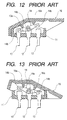
- FIG. 12 and FIG. 13 are side cross sectional views of the switch assembly described in FIG. 11.
- the conventional lever operation type switch assembly comprises a box-shaped housing 11 having a container 11a formed of synthetic resin, a plurality of common contact points 12 and individual contact points 13 that are formed of conductive metal plates disposed on the inside bottom surface of the container 11a of the housing 11, a movable contact member 14 formed of conductive metal material having a support tongue 14a that is in contact elastically with the common contact points 12 normally, supported pivotally and swingably on the top end sides of the abovementioned common contact points 12 and having elastic contact tongues 14b disposed on both end sides of the abovementioned support tongue 14a that are brought into connection/disconnection to/from the abovementioned individual contact points with swinging of the movable contact member 14, an operation lever 16 formed of synthetic resin that is supported pivotally on the abovementioned housing 11 to swing the abovementioned movable contact member 14, and a return spring 15 disposed between the operation lever 16 and the abovementioned housing 11 that is served to return the operation lever 16 to the original position.
- the conventional lever operation type switch assembly having the structure described hereinabove is fabricated through the process in which a conductive metal plate is pressed to form a plurality of common contact points 12 and individual contact points 13, and the common contact points 12 and the individual contact points 13 are fixed on the inside bottom surface of the container 11a of the abovementioned housing 11 by means of caulking by use of a press tool or by means of bonding with adhesive.
- an axial hole 14c formed on the upper surface at the center of the abovementioned movable contact member 14 is engaged with projection members 12a formed at the top end side of the of the abovementioned common contact points 12, and the abovementioned movable contact member 14 is formed swingable round the projection members 12a.
- Actuation projections 16a formed on the inside surface of the operation lever 16 push the upper surface side of the abovementioned movable contact member 14 concomitantly with pivoting of the abovementioned operation lever 16 so that the abovementioned movable contact member 14 is swung round the abovementioned projection members 12a, and the pair of elastic contact tongues 14b are resultantly connected to or disconnected from the abovementioned individual contact points 13.
- the abovementioned support tongue 14a is in contact elastically with the abovementioned common contact points 12 normally.
- the one of the pair of the abovementioned elastic contact tongues 14b is connected (ON) to the abovementioned individual contact points 13
- the other of the abovementioned elastic contact tongues 14b is disconnected (OFF) from the other of the abovementioned individual contact points 13.
- the abovementioned conventional switch assembly has the structure in which the abovementioned axial hole 14c formed at the center of the upper surface of the abovementioned movable contact member 14 is engaged with the abovementioned projection members 12a that are portions of top end sides of the abovementioned common contact points 12 formed of plate-like metal plate so that the abovementioned movable contact member 14 is supported swingably, therefore the plate-like metal plate is used inevitably due to direct support on the abovementioned common contact points 12, and the material to be used for fabrication cannot be saved.
- the height of the elastic contact member of the abovementioned individual contact points 13 from which the elastic contact holding member of the abovementioned elastic contact tongues 14b is disconnected must be changed, the abovementioned individual contact points 13 of a plurality of types should be in stock so as to be ready for required specification, and the parts of the abovementioned individual contact points 13 cannot be commonly used.
- the present invention has been accomplished to solve the abovementioned problem, and it is an object of the present invention to provide a switch assembly advantageous in that the movable contact member is stably supported swingably, the structure of the configuration of the common contact point and individual contact point is simplified to reduced the material cost, and the parts of the common contact point and individual contact point are used commonly.
- another object of the present invention is to provide a switch assembly that is capable of changing the connection (ON)/disconnection (OFF) switching timing of the switch by use of one type of the individual contact point without stocking of the individual contact point of a plurality of types, and the configuration of the individual contact point of the switch assembly is simplified and the parts is used commonly.
- a switch assembly comprises a housing having a container, a common contact point, and an individual contact point disposed in the container, a support tongue that is in contact with the common contact point normally, and an elastic contact tongue that is connected to or disconnected from the individual contact point, and is provided with a movable contact member supported swingably in the container, and an operation lever supported pivotally on the housing that is served to swing the movable contact member, wherein a support projection that extends to a free end side from the elastic contact position of the common contact point is formed on a support tongue of the movable contact member, and wherein the support projection is supported by means of a pivot support portion formed on the housing.
- the second means of the present invention is characterized in that the support projection formed on the support tongue is formed so as to extend to an inside bottom surface side of the housing against an elastic contact point of the support tongue and the common contact position.
- the third means of the present invention is characterized in that the end surface on the free end side of the support projection is formed in the shape of a circular arc, and the support projection formed in the shape of a circular arc is supported pivotally on a pivot support member in the shape of a circular arc formed in the housing.
- the forth means of the present invention is characterized in that the pivot support portion comprises a projection having a circular arc surface formed combinedly with the housing.
- a switch assembly comprises a housing having a container, a common contact point and an individual contact point having one end side disposed on an inside bottom surface of the container and having another end side projected from a bottom portion of the housing, a support tongue that is in contact with the common contact point normally, and an elastic contact tongue that is connected to or disconnected from the individual contact point, and being provided with a movable contact member supported swingably in the container, and an operation lever supported pivotally on the housing that is served to swing the movable contact member, wherein the common contact point and the individual contact point are formed of rod-like circular cross sectional wire, press-inserted and held in the housing, and wherein a wave corresponding to an inside surface of a press-insertion holding portion of the housing is formed on a side surface of the common contact point and the individual contact point.
- the sixth means of the present invention is characterized in that the common contact point and the individual contact point are formed of circular cross sectional wire having the same length, and that a length from the wave formed on respective circular cross sectional wires to the respective end surfaces is formed approximately in the same length.
- the seventh means of the present invention is characterized in that the common contact point and the individual contact point are press-inserted and held in the housing so that the wave is exposed partially from the bottom of the housing.
- the eighth means of the present invention is characterized in that the one end side of the common contact point and the individual contact point formed of circular cross sectional wire is projected to the inside bottom surface of the container of the housing, and that a side surface of the one end side is held between a support tongue and an elastic tongue member of the movable contact member.
- a switch assembly comprises a housing having a container, a common contact point and an individual contact point having the one end side disposed projectingly to the inside bottom surface of the container, a support tongue that is in contact with the common contact point normally, and an elastic contact tongue that is connected to or disconnected from the individual contact point, and being provided with a movable contact member supported swingably in the container, and an operation lever supported pivotally on the housing that is served to swing the movable contact member, wherein an insulating wall that is projected to the projection direction of the individual contact point and served to further open so that an elastic contact tongue of the movable contact member is disconnected from the individual contact point is formed on the container.
- the tenth means of the present invention is characterized in that the insulating wall comprises a projection formed combinedly with the housing, and the projection has a thin end guide served to further open the elastic contact tongue of the movable member that is disconnected from the individual contact point.
- the eleventh means of the present invention is characterized in that the guide is formed with interposition of a certain distance near the projection position of the individual contact point disposed on the inside bottom surface of the container.
- the twelfth means of the present invention is characterized in that a plurality of sets of the common contact points and the individual contact points are formed on the container of the housing, and a projection direction height of the insulating wall corresponding to the individual contact points is formed differently.
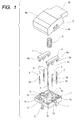
- FIG. 1 is an exploded perspective view showing a lever operation type switch assembly
- FIG. 2 is a perspective view showing the whole lever operation type switch assembly shown in FIG. 1
- FIG. 3 is a side cross sectional view showing the operation lever setting before an operation is started
- FIG. 4 is a side cross sectional view of the lever operation type switch assembly showing the setting when the operation lever is operated
- FIG. 5 is a plan view of a housing
- FIG. 6 is a side cross sectional view of the lever operation type switch assembly
- FIG. 7 is an explanatory diagram showing another embodiment of the movable contact point and individual contact points that are in an ON state
- FIG. 8 is an explanatory diagram showing the setting in an OFF state
- FIG. 9 is an explanatory diagram showing another example that is in an OFF state
- FIG. 10 is an explanatory diagram showing another embodiment that is in an ON state.
- the housing 1 is formed of insulating material such as synthetic resin in the shape of a box with a container 1a having an open aperture on the upper surface.
- a spring container 1b that is a concave circular hole and served to contain a return spring, which will be described hereinafter, is formed at the center of the container 1a of the housing 1.
- a pair of pivot support portions 1c that are projections for supporting a movable contact member 4 pivotally, which will be described hereinafter, are formed at the center of the both side surfaces that are facing each other with interposition of the spring container 1b.
- Contact point insertion holes 1d to which the common contact point 2, which will be described hereinafter, is press-inserted are formed at the centers of the pivot support portion 1c.
- a pair of pivot faces 1e shaped in the form of circular arc are formed on both sides with interposition of the contact point insertion holes 1d.
- the pivot faces 1e are engaged with the support projection 4c shaped in the form of circular arc disposed at the top end of the support tongue 4a of the movable contact point 4, which will be described hereinafter, and are supported pivotally.
- a plurality of insulating walls 1f are formed in the form of projection with interposition of the abovementioned pivot support portion 1c on both side surfaces of the abovementioned container 1a.
- Contact point insertion holes 1g to which individual contact points 3, which will be described hereinafter, are press-inserted so as to be held are formed at the point approximately near the center of the insulating walls 1f.
- a guide having a thin end for opening the elastic contact tongue 4b of the movable contact member 4 that is to be disconnected from the individual contact 3, which will be described hereinafter, is formed solidly in the form of projection directed to the projection direction of the individual contact point 3.
- the temporal connection/disconnection timing to change ON/OFF of the switch can be changed by changing the projection height corresponding to an individual contact point of the guide 1h.
- the common contact points 2 and the individual contact points 3 are formed by cutting conductive rod-like circular metal material into a certain same length.
- a plurality of waves 2a and 3a corresponding to the inside surface of the abovementioned contact point insertion holes 1d and 1g that are served as the press-insertion holding portion of the abovementioned housing 1 are formed by means of press working to form different thickness at the center of the side surface of circular rods of the common contact points 2 and individual contact points 3.
- the waves 2a and 3a are formed so that the length from the end of the waves 2a and 3a formed on the individual circular rods to the respective top end surfaces is substantially the same. Thereby, it is not necessary to distinguish the direction when it is inserted into the abovementioned contact point insertion holes 1d and 1g, and it is inserted easily.
- the abovementioned common contact points 2 and the individual contact points 3 are formed so as to be press-inserted and held in the abovementioned housing 1 wherein the abovementioned wave 2a and 3a are exposed partially from the bottom of the abovementioned housing 1.
- the wave 2a and 3a functions to extend the flux penetration distance, and the groove of the wave functions as the flux pond. Thereby, the flux penetration is suppressed when soldering.
- the movable contact member 4 is formed by bending an elastic conductive thin metal plate in the form of clip.
- the support tongue 4a that is in elastic contact normally with the common contact points 2 is formed at the center of the movable contact member 4, and a pair of elastic contact tongues 4b that are connected to or disconnected from the abovementioned individual contact points 3 are formed on both sides with interposition of the support tongue 4a.
- a support projection 4c that extends to the free end side from the elastic contact position of the abovementioned common contact points 2 is formed on the abovementioned support tongue 4a, and the support projection 4c is formed projectingly to the inside bottom surface side of the abovementioned housing 1 with respect to the elastic contact position between the abovementioned support tongue 4a and the abovementioned common contact points 2.
- the end face of the free end side of the abovementioned support projection 4c is shaped in the form of arc, and the abovementioned arc-like support projection 4c is supported pivotally on the pivot face 1e of the abovementioned arc-like pivot support portion 1c formed on the abovementioned housing 1.
- the abovementioned support projection 4c of the abovementioned movable contact member 4 is supported pivotally on the abovementioned pivot support portion 1c, and the support tongue 4a is in elastic contact normally with the abovementioned common contact points 2.
- the abovementioned elastic contact tongue 4b slides between the abovementioned individual contact points 3 and the guide 1h of the abovementioned insulating wall 1f concomitantly with pivot operation of the operation lever 6, which will be described hereinafter, and the contact point is connected or disconnected between the abovementioned common contact points 2 and the abovementioned individual contact points 3, and the contact point is operated between ON and OFF.
- the return spring 5 is formed of a coil spring, the one end of which spring 5 is hooked to the spring container 1b of the abovementioned housing 1 and the other end is hooked to the spring hooking portion not shown in the drawings of the operation lever 6, which will be described hereinafter. Thereby, the operation lever 6 is returned to the original position.
- the operation lever 6 is formed of insulating material such as synthetic resin, and comprises a cover portion 6a that is shaped approximately in the form of a box having an open bottom and an operation portion 6b formed projectingly to one end of the cover portion 6a longitudinally. Furthermore, a pair of axial holes 6c that are supported by a pair of support shafts 1i formed on the abovementioned housing 1 are formed on both side surfaces of the abovementioned cover portion 6a.
- the inside bottom surface of the abovementioned cover portion 6a is brought into contact with the upper surface portion of the abovementioned movable contact member 4 to pivot the abovementioned pivot support portion 1c of the abovementioned housing 1 round the abovementioned pivot support portion 1c with pivoting of the abovementioned operation lever 16.
- the abovementioned operation lever 6 is pivotally pressed in the anti-clock direction by means of the pressing force of the abovementioned return spring 5.
- the support tongue 4a of the abovementioned movable contact member 4 is in contact with the abovementioned common contact points 2 normally, and the right side elastic contact tongue out of the abovementioned pair of the abovementioned elastic contact tongues 4b is in contact with the right individual contact points out of the abovementioned pair of individual contact points 3 (shown in FIG. 7).
- the aperture of the left side elastic contact tongue 4b is enlarged by means of the abovementioned insulating wall 1f, and is disconnected from the left individual contact point 3 (shown in FIG. 8)
- the aperture of the right side elastic contact tongue 4b (that has been ON) of the abovementioned movable contact member 4 is enlarged by means of the abovementioned insulating wall 1f so as to be disconnected from the right side individual contact point 3 and turned OFF, and on the other hand the left side elastic contact tongue 4b that has been OFF changes to ON state because the left elastic contact tongue 4b is disconnected from the abovementioned insulating wall 1f and connected to the abovementioned individual contact point 3.
- the pushing pressure applied on the abovementioned operation portion 6b is released to change the abovementioned state, and the abovementioned operation lever 6 is restored to the initial state shown in FIG. 3 by means of the pressing force of the return spring 5.
- the structure of the present invention is advantageous in that the abovementioned movable contact member 4 is swingably supported stably even though the abovementioned common contact point 2 and the individual contact point 3 are replaced with simple rod
- the abovementioned support projection member 4c formed on the abovementioned support tongue 4a is formed so as to extend to the inside bottom surface side of the container 1c of the abovementioned housing 1 with respect to the elastic contact position where the abovementioned support tongue 4a holds the abovementioned common contact point 2 slidably, the adhesion of wearing dust on the elastic contact position is prevented because the wearing dust occurs at the location under the elastic contact point of the abovementioned common contact point 2, even though wearing dust occurs due to sliding between the abovementioned support projection member 4c and the pivot support portion 1c of the abovementioned housing 1. As the result, the contact is very stable.
- the pivotal support portion can be formed with the simple structure and the pivotal operation is stabilized.
- the insulating wall 1f that projects in the projection direction of the abovementioned individual contact point 3 is formed on the inside bottom surface of the abovementioned container 1a as the ON/OFF structure of the contact point portion of the switch and the insulating wall 1f holds the elastic contact tongue 4b of the abovementioned movable contact member 4 for opening the aperture so that the abovementioned individual contact point 3 is disconnected to turn off the contact point portion, it is made possible to change the temporal ON/OFF timing when the switch is turned between ON and OFF.
- the abovementioned insulating wall 1f has the projection formed combinedly with the abovementioned housing 1 and the abovementioned guide 1h having the thin end configuration that is served to further open the elastic contact tongue 4b of the abovementioned movable contact member 4 that is disconnected from the abovementioned individual contact point 3 is formed on the projection, it is possible to change the variety easily with only changing the abovementioned guide 1h.
- the abovementioned guide 1h is formed on the abovementioned insulating wall 1f formed projectingly to the inside bottom surface of the abovementioned container 1a near the position where the abovementioned individual contact point 3 projects apart from the individual contact point 3 with a certain distance, it is possible to prevent deterioration of the resin wall of the abovementioned insulating wall 1f due to the arc that is generated when the switch is turned. As the result, the abovementioned configuration brings about consistent switching of the contact point portion.
- the container 1a of the abovementioned housing 1 is provided with a plurality of sets of the abovementioned common contact points 2 and individual contact points 3 and the projection direction height of the guides 1h of the abovementioned insulating wall 1f corresponding to the abovementioned respective individual contact points 3 is formed differently, it is possible to change the switching timing of the switch in the same switch respectively to bring about the wide-range various accommodation.
- FIG. 9 and FIG. 10 show the structure of another insulating wall 1f example.
- the guide 1h formed on the insulating wall 1f having the thin end configuration that is served to further open the elastic contact tongue 4b of the abovementioned movable contact member 4 to be disconnected from the abovementioned individual contact point 2 is formed combinedly with the abovementioned insulating wall 1f so as to be positioned on the top end side of the abovementioned individual contact point 3 in the direction opposite to the projection direction of the abovementioned individual contact point 3 (inside bottom surface side of the abovementioned container 1a), and the abovementioned insulating wall 1f is formed combinedly so as to project from the inside side surface of the abovementioned housing 1.
- the abovementioned elastic contact tongue 4b is further opened by means of the abovementioned guide 1h when the abovementioned movable contact member 4 pivots in the direction so as to be separated from the inside bottom surface of the abovementioned housing 1 (upward direction in the drawing), and on the other hand the abovementioned elastic contact tongue 4b, which has ridden on the abovementioned guide 1h, comes apart from the abovementioned guide 1h when the abovementioned movable contact member 4 pivots in the direction so as to come near to the inside bottom surface of the abovementioned housing 1 (downward direction in the drawing) and the abovementioned individual contact point 3 is brought into contact.
- ON/OFF switching of the switch shown in FIG. 3 and FIG. 4 is inverted between the right and left individual contact points 3.
- the abovementioned common contact point 2 is connected (ON) to the abovementioned left side individual contact point 3, and on the other hand the abovementioned common contact point 2 is disconnected (OFF) from the abovementioned right side individual contact point 3.
- the switch assembly of the present invention having the structure in which a support projection that extends to the free end side from the elastic contact position of the common contact point is formed on the support tongue of the movable contact member supported pivotally in the container of the housing having the common contact point and individual contact point to have the support projection supported on a pivot support portion formed in the housing, the movable contact member can be pivotally supported stably even though the common contact points and individual contact points are changed to be of thin circular wire.
- the contact point can be formed of simple rod-like circular cross sectional wire, the material cost and working cost can be reduced, and parts of the common contact point and individual contact points can be used commonly.
- the support projection formed on the support tongue is formed so as to extend to the inside bottom surface side of the housing with respect to the elastic contact position between the support tongue and the common contact point, the wearing dust is generated at the position under the elastic contact with the common contact point even though wearing dust is generated due to sliding between the support projection and the pivot support portion of the housing in pivoting. As the result, adhesion of wearing dust on the elastic contact position of the common contact point and the stable contact is realized.
- the pivot support portion can be formed with simple structure. As the result, the stable pivot operation can be realized.
- the pivot support portion comprises the projection having the circular arc surface formed combinedly with the housing, the structure can be simplified and the manufacturing cost can be reduced.
- the switch assembly of the present invention having the structure in which the one end side that is to be brought into elastic contact with the movable contact member supported swingably on the housing is disposed on the inside bottom surface of the container and the common contact point and individual contact point having the other end side that projects from the bottom portion of the housing is formed of rod-like circular cross sectional wire, and the wave portion corresponding to the inside surface of the press-insertion holding portion of the housing is formed on the side surface of the common contact point and the individual contact point that are press-inserted and held in the housing, the wave portion having the different thicknesses can be engaged strongly with the press-insertion holding portion and resin on the inside surface of the press-insertion portion is softened and penetrates into the wave portion with aid of heating for soldering when the switch is mounted on a circuit substrate, and the resin is solidified. As the result, the common contact point and individual contact point can be fixed firmly to the housing.
- the common contact point and the individual contact point are formed of circular cross sectional wire having the same length and the length from the wave formed on the respective circular cross sectional wires to the respective end surfaces is formed approximately in the same length, the directional discrimination of the common contact point and the individual contact point can be unnecessary when the common contact point or the individual contact point is to be inserted into a contact point insertion hole. As the result the common contact point and the individual contact point can be inserted easily and the fabrication work efficiency can be improved.
- the wave allows the flux to penetrate farther and the grooves of the wave can be served as the flux pond. As the result, the flux flow during soldering can be suppressed.
- the structure of the contact point portion can be made simple and the low manufacturing cost can be realized.
- the switch assembly of the present invention having the structure in which the insulating wall that is projected in the projection direction of the individual contact point and that is served to further open so that the elastic contact tongue of the movable contact member is disconnected from the individual contact point is formed on the container of the housing where the one end side of the common contact point and the individual contact point, on which the support tongue and the elastic contact tongue of the movable contact member supported swingably are in elastic contact, is projected, the temporal ON/OFF timing of the switch can be changed by changing the configuration of the insulating wall. As the result, it is possible to easily realize the wide-range various accommodation of the switching timing of the switch.
- the insulating wall comprises the projection formed combinedly with the housing, and the guide having the thin end that is served to further open the elastic contact tongue of the movable contact member disconnected from the individual contact point is formed on the projection, it is possible to easily realize the wide-range various accommodation with only suitable modification of the guide.
- the guide is formed with interposition of a certain distance near the projection position of the individual contact point disposed on the inside bottom surface of the container, the deterioration of the resin wall of the insulating wall due to arc generated when the switch is turned can be prevented and the contact point portion can be switched consistently.
Landscapes
- Physics & Mathematics (AREA)
- Electromagnetism (AREA)
- Rotary Switch, Piano Key Switch, And Lever Switch (AREA)
- Tumbler Switches (AREA)
- Switch Cases, Indication, And Locking (AREA)
- Breakers (AREA)
Abstract
Description
Claims (12)
- A switch assembly comprising a housing having a container, a common contact point and an individual contact point disposed in the container, a support tongue that is in contact with the common contact point normally, and an elastic contact tongue that is connected to or disconnected from the individual contact point, and being provided with a movable contact member supported swingably in the container, and an operation lever supported pivotally on the housing that is served to swing the movable contact member, wherein a support projection that extends to a free end side from the elastic contact position of the common contact point is formed on a support tongue of the movable contact member, and wherein the support projection is supported by means of a pivot support portion formed on the housing.
- The switch assembly according to claim 1, wherein the support projection formed on the support tongue is formed so as to extend to an inside bottom surface side of the housing against an elastic contact point of the support tongue and the common contact position.
- The switch assembly according to claim 1 or 2, wherein the end surface on the free end side of the support projection is formed in the shape of a circular arc, and the support projection formed in the shape of a circular arc is supported pivotally on a pivot support member in the shape of a circular arc formed in the housing.
- The switch assembly according to claim 3, wherein the pivot support portion comprises a projection having a circular arc surface formed combinedly with the housing.
- A switch assembly comprising a housing having a container, a common contact point and an individual contact point having the one end side disposed on an inside bottom surface of the container and having another end side projected from a bottom portion of the housing, a support tongue that is in contact with the common contact point normally, and an elastic contact tongue that is connected to or disconnected from the individual contact point, and being provided with a movable contact member supported swingably in the container, and an operation lever supported pivotally on the housing that is served to swing the movable contact member, wherein the common contact point and the individual contact point are formed of rod-like circular cross section wire, press-inserted and held in the housing, and wherein a wave corresponding to an inside surface of a press-insertion holding portion of the housing is formed on a side surface of the common contact point and the individual contact point.
- The switch assembly according to claim 5, wherein the common contact point and the individual contact point are formed of circular cross sectional wire having the same length, and wherein a length from the wave formed on the respective circular cross sectional wires to a respective end surfaces is formed approximately in the same length.
- The switch assembly according to claim 5 or 6, wherein the common contact point and the individual contact point are press-inserted and held in the housing so that the wave is exposed partially from the bottom of the housing.
- The switch assembly according to any one of claims 5 to 7, wherein the one end side of the common contact point and the individual contact point formed of circular cross sectional wire is projected to the inside bottom surface of the container of the housing, and wherein a side surface of the one end side is held between a support tongue and an elastic tongue member of the movable contact member.
- A switch assembly comprising a housing having a container, a common contact point and an individual contact point having the one end side disposed projectingly to the inside bottom surface of the container, a support tongue that is in contact with the common contact point normally, and an elastic contact tongue that is connected to or disconnected from the individual contact point, and being provided with a movable contact member supported swingably in the container, and an operation lever supported pivotally on the housing that is served to swing the movable contact member, wherein an insulating wall that is projected to the projection direction of the individual contact point and served to further open so that an elastic contact tongue of the movable contact member is disconnected from the individual contact point is formed on the container.
- The switch assembly according to claim 9, wherein the insulating wall comprises a projection formed combinedly with the housing, and the projection has a thin end guide served to further open the elastic contact tongue of the movable member that is disconnected from the individual contact point.
- The switch assembly according to claim 10, wherein the guide is formed with interposition of a certain distance near the projection position of the individual contact point disposed on the inside bottom surface of the container.
- The switch assembly according to any one of claims 9 to 11, wherein a plurality of sets of the common contact points and the individual contact points are formed on the container of the housing, and a projection direction height of the insulating wall corresponding to the individual contact points is formed differently.
Applications Claiming Priority (6)
| Application Number | Priority Date | Filing Date | Title |
|---|---|---|---|
| JP2000340408 | 2000-11-02 | ||
| JP2000340409 | 2000-11-02 | ||
| JP2000340408A JP3807927B2 (en) | 2000-11-02 | 2000-11-02 | Switch device |
| JP2000340409A JP3835982B2 (en) | 2000-11-02 | 2000-11-02 | Switch device |
| JP2000340410A JP3807928B2 (en) | 2000-11-02 | 2000-11-02 | Switch device |
| JP2000340410 | 2000-11-02 |
Publications (2)
| Publication Number | Publication Date |
|---|---|
| EP1204128A2 true EP1204128A2 (en) | 2002-05-08 |
| EP1204128A3 EP1204128A3 (en) | 2005-01-05 |
Family
ID=27345144
Family Applications (1)
| Application Number | Title | Priority Date | Filing Date |
|---|---|---|---|
| EP01126042A Withdrawn EP1204128A3 (en) | 2000-11-02 | 2001-10-31 | Lever operating type switch assembly |
Country Status (4)
| Country | Link |
|---|---|
| EP (1) | EP1204128A3 (en) |
| KR (1) | KR100453999B1 (en) |
| CN (1) | CN1201353C (en) |
| TW (1) | TW509956B (en) |
Family Cites Families (6)
| Publication number | Priority date | Publication date | Assignee | Title |
|---|---|---|---|---|
| FR685294A (en) * | 1929-11-21 | 1930-07-08 | L App Electr De La Seine Soc | Light switch |
| FR1348817A (en) * | 1962-02-28 | 1964-01-10 | Merlin Gerin | Sliding contacts for electrical switches |
| DE1540189A1 (en) * | 1965-10-16 | 1970-01-02 | Markwortit Gmbh | ? of contact plates for? for radio and? Magnetic sound device or the like. |
| JPS608355Y2 (en) * | 1979-12-31 | 1985-03-25 | 日本開閉器工業株式会社 | Pin terminal type switch |
| US4740661A (en) * | 1985-03-08 | 1988-04-26 | Kabushiki Kaisha Sagami Denshi Kogyo | Seesaw switch |
| JP2573191Y2 (en) * | 1991-02-22 | 1998-05-28 | アルプス電気株式会社 | Movable contact support structure for swing switch |
-
2001
- 2001-10-16 TW TW090125580A patent/TW509956B/en not_active IP Right Cessation
- 2001-10-29 KR KR10-2001-0066637A patent/KR100453999B1/en not_active Expired - Fee Related
- 2001-10-30 CN CNB011361387A patent/CN1201353C/en not_active Expired - Fee Related
- 2001-10-31 EP EP01126042A patent/EP1204128A3/en not_active Withdrawn
Also Published As
| Publication number | Publication date |
|---|---|
| KR20020034886A (en) | 2002-05-09 |
| TW509956B (en) | 2002-11-11 |
| EP1204128A3 (en) | 2005-01-05 |
| CN1352459A (en) | 2002-06-05 |
| KR100453999B1 (en) | 2004-10-26 |
| CN1201353C (en) | 2005-05-11 |
Similar Documents
| Publication | Publication Date | Title |
|---|---|---|
| US6773287B2 (en) | Electrical connector for flat conductor | |
| JPH02500786A (en) | electromagnetic relay | |
| US5945900A (en) | Electromagnetic contactor | |
| KR20080059521A (en) | Terminal device | |
| US6689967B2 (en) | Slide switch | |
| US7135651B2 (en) | Detect switch with an improved moveable contact | |
| JP3956806B2 (en) | Push button switch | |
| JP3807928B2 (en) | Switch device | |
| JP3835982B2 (en) | Switch device | |
| JP4256708B2 (en) | Switch device | |
| JP3807927B2 (en) | Switch device | |
| JP4023884B2 (en) | Contact opening / closing mechanism of switch device | |
| US6071133A (en) | Electrical card connector with multi-stroke ejector means | |
| KR101630242B1 (en) | Lever switch | |
| KR100453999B1 (en) | Lever operating type switch device | |
| JP3895639B2 (en) | On-off switch and thereby dual in-line mounting | |
| KR100298507B1 (en) | switch | |
| CN101071692A (en) | Switching device | |
| KR100427855B1 (en) | Connector with a switching function | |
| JP4715694B2 (en) | switch | |
| CN100458993C (en) | Switch contact structure | |
| JP3858303B2 (en) | Automatic reset slide switch | |
| JP4455864B2 (en) | Mounting structure of sliding resistance board in power tool switch | |
| EP1930927A1 (en) | Electric switch with a pivoting switching member | |
| KR200226851Y1 (en) | A micro switch |
Legal Events
| Date | Code | Title | Description |
|---|---|---|---|
| PUAI | Public reference made under article 153(3) epc to a published international application that has entered the european phase |
Free format text: ORIGINAL CODE: 0009012 |
|
| AK | Designated contracting states |
Kind code of ref document: A2 Designated state(s): AT BE CH CY DE DK ES FI FR GB GR IE IT LI LU MC NL PT SE TR |
|
| AX | Request for extension of the european patent |
Free format text: AL;LT;LV;MK;RO;SI |
|
| PUAL | Search report despatched |
Free format text: ORIGINAL CODE: 0009013 |
|
| AK | Designated contracting states |
Kind code of ref document: A3 Designated state(s): AT BE CH CY DE DK ES FI FR GB GR IE IT LI LU MC NL PT SE TR |
|
| AX | Request for extension of the european patent |
Extension state: AL LT LV MK RO SI |
|
| 17P | Request for examination filed |
Effective date: 20050614 |
|
| AKX | Designation fees paid |
Designated state(s): DE ES FR GB IT |
|
| 17Q | First examination report despatched |
Effective date: 20080409 |
|
| STAA | Information on the status of an ep patent application or granted ep patent |
Free format text: STATUS: THE APPLICATION IS DEEMED TO BE WITHDRAWN |
|
| 18D | Application deemed to be withdrawn |
Effective date: 20080820 |