EP1203978A1 - Equipment optique destiné à être aéroportés - Google Patents
Equipment optique destiné à être aéroportés Download PDFInfo
- Publication number
- EP1203978A1 EP1203978A1 EP01402747A EP01402747A EP1203978A1 EP 1203978 A1 EP1203978 A1 EP 1203978A1 EP 01402747 A EP01402747 A EP 01402747A EP 01402747 A EP01402747 A EP 01402747A EP 1203978 A1 EP1203978 A1 EP 1203978A1
- Authority
- EP
- European Patent Office
- Prior art keywords
- window
- optical
- porthole
- optical equipment
- equipment according
- Prior art date
- Legal status (The legal status is an assumption and is not a legal conclusion. Google has not performed a legal analysis and makes no representation as to the accuracy of the status listed.)
- Granted
Links
Images
Classifications
-
- F—MECHANICAL ENGINEERING; LIGHTING; HEATING; WEAPONS; BLASTING
- F41—WEAPONS
- F41G—WEAPON SIGHTS; AIMING
- F41G7/00—Direction control systems for self-propelled missiles
- F41G7/20—Direction control systems for self-propelled missiles based on continuous observation of target position
- F41G7/22—Homing guidance systems
- F41G7/2273—Homing guidance systems characterised by the type of waves
- F41G7/2293—Homing guidance systems characterised by the type of waves using electromagnetic waves other than radio waves
-
- F—MECHANICAL ENGINEERING; LIGHTING; HEATING; WEAPONS; BLASTING
- F41—WEAPONS
- F41G—WEAPON SIGHTS; AIMING
- F41G7/00—Direction control systems for self-propelled missiles
- F41G7/20—Direction control systems for self-propelled missiles based on continuous observation of target position
- F41G7/22—Homing guidance systems
- F41G7/2213—Homing guidance systems maintaining the axis of an orientable seeking head pointed at the target, e.g. target seeking gyro
-
- G—PHYSICS
- G01—MEASURING; TESTING
- G01C—MEASURING DISTANCES, LEVELS OR BEARINGS; SURVEYING; NAVIGATION; GYROSCOPIC INSTRUMENTS; PHOTOGRAMMETRY OR VIDEOGRAMMETRY
- G01C11/00—Photogrammetry or videogrammetry, e.g. stereogrammetry; Photographic surveying
- G01C11/02—Picture taking arrangements specially adapted for photogrammetry or photographic surveying, e.g. controlling overlapping of pictures
-
- G—PHYSICS
- G02—OPTICS
- G02B—OPTICAL ELEMENTS, SYSTEMS OR APPARATUS
- G02B27/00—Optical systems or apparatus not provided for by any of the groups G02B1/00 - G02B26/00, G02B30/00
- G02B27/64—Imaging systems using optical elements for stabilisation of the lateral and angular position of the image
- G02B27/644—Imaging systems using optical elements for stabilisation of the lateral and angular position of the image compensating for large deviations, e.g. maintaining a fixed line of sight while a vehicle on which the system is mounted changes course
Definitions
- the invention relates to the field of optical equipment. intended to be airborne.
- Optical equipment includes a subset optical system having a line of sight, for example a light or a light emitter.
- the optical sub-assembly is protected from the external environment by an external envelope.
- the envelope exterior has a movable follower hood and at least one porthole transparent in a given optical spectral range.
- the porthole is united of the follower hood and fixed relative to the follower hood. The porthole allows optical communication between the optical sub-assembly and the exterior.
- the movable follower hood allows the porthole, and the line of sight of the sub-assembly optics whose displacement is harmonized with that of the window, to move in an important angular domain of the external space, for example by scanning in a portion of a space during the flight of the aircraft.
- the subset optic is isolated from its supporting structure by an anti-vibration suspension filtering mechanical stresses.
- the optical equipment In operational conditions, the optical equipment is integrated into an aircraft.
- the line of sight of the optical sub-assembly must be able to be oriented in an important angular domain, in particular in the case where optical equipment has a substantially ball shape and where the cover follower has a spherical shape.
- the flat porthole carried by the follower hood is so led to take positions with high incidence in relation to the direction of movement of the aircraft to which the optical equipment is integrated, i.e. the normal outside the window can make an angle important with the direction of movement of said aircraft in particular when the optical sub-assembly and therefore also the window "look" towards the rear of said aircraft.
- the aerodynamic flow at the window that is to say the air flows in front of the window, is then very disturbed, it is actually turbulent.
- edges at the interface existing between the plane of the porthole and the sphere portion of the follower hood generate primers of turbulence making the aerodynamic flow turbulent at the level of the porthole.
- This turbulent flow in front of the entrance pupil of the sub-assembly optical causes for example loss of resolution at the level of the optical sub-assembly which are troublesome, in particular when the sub-assembly optics works in a short optical spectral range wavelengths, for example the visible or the near infrared.
- the invention is based on the use, in optical equipment, a porthole whose spherical outer surface has a continuity of form with the outer surface of the follower hood. This continuity of form is sufficient not to substantially increase the disturbances of aerodynamic flow at the window. An increase in disruption becomes substantial when, for the intended application, this increase in disturbances significantly degrades the operation of the optical equipment according to the invention. In order to decrease strongly even eliminate the discomfort of residual movements relative between the window and the optical sub-assembly, the window is rendered afocal.
- optical equipment intended for be airborne with an optical sub-assembly protected by a cover mobile follower and through a porthole secured to the follower hood and fixed relative to to the follower hood, characterized in that the window is afocal, in that the exterior surface of the window is spherical, in that the line of sight of the optical subassembly passes through the center of curvature of the surface exterior of the window, and in that the exterior surface of the window has continuity in shape with the outer surface of the follower hood.
- optical equipment intended to be airborne comprising a supporting structure, a sub-assembly optic having a line of sight and being both suspended from the support structure and mechanically isolated from the support structure by a anti-vibration suspension filtering mechanical stress, an envelope exterior protecting the optical sub-assembly from the environment exterior, the exterior envelope comprising a movable follower cover by compared to the supporting structure and a porthole which allows a optical communication in a given spectral domain between the subset optical and exterior, the porthole being surrounded by the follower hood and fixed relative to the follower hood, characterized in that the surface exterior of the window is spherical, in that the line of sight of the sub-assembly optics pass through the center of curvature of the outer surface of the window in the absence of mechanical stresses exerted on the structure carrier, in that the exterior surface of the window and the exterior surface of the follower cover have a continuity of shape between them at the level of their junction so as not to substantially
- the invention relates to optical equipment intended to be airborne.
- Optical equipment intended to be airborne is a equipment intended to be integrated into an aircraft.
- Optical equipment comprises an optical sub-assembly having a line of sight.
- the subset optic having a line of sight is for example either one or several light sensors either one or more light emitters or a device grouping together one or more light emitters and one or more light sensors.
- the optical equipment includes a supporting structure.
- the subset optic is suspended from the supporting structure.
- the subset optics is at the same time mechanically isolated from the supporting structure by an anti-vibration suspension filtering mechanical stresses.
- the mechanical stresses are for example vibrations, shocks, acceleration.
- An important vibratory environment risks generating blur for example at the level of the images provided by the light sensor when the optical sub-assembly includes a light sensor.
- the antivibration suspension includes for example on the one hand a loop of gyroscopic stabilization to filter mechanical stresses at low frequency and on the other hand of the elastomeric blocks to filter the stresses high frequency mechanical, high frequency including preferably frequencies above a few tens of Hertz, typically greater than 30 Hertz.
- the optical sub-assembly is protected from the environment exterior by an exterior envelope.
- the outer shell is preferably waterproof, guaranteeing a dry and advantageously a controlled temperature.
- the outer envelope comprises a movable follower cover with respect to the support structure and a porthole which allows optical communication in a spectral domain given between the optical sub-assembly and the exterior.
- the spectral domain given is an optical spectral domain which includes one or more lines and / or one or more spectral bands in a domain extending from far infrared ultraviolet.
- the porthole is surrounded by the follower hood and fixed relative to the follower hood.
- the mobile follower hood allows the window, as well as the line of sight of the optical sub-assembly which is preference stabilized and whose displacement is harmonized with that of porthole, to move in an important angular domain of space outside, for example by scanning in a portion of a given observation space, during the flight of the aircraft, for example in the case where the optical sub-assembly comprises at least one sensor for light.
- the window has a symmetry of revolution
- the line of sight of the optical sub-assembly and the axis of revolution of the porthole are harmonized, one of the two being generally subject to the other.
- At least the useful part of the window i.e. the part of the window by which passes the useful light information circulating between the sub-assembly optical and exterior, generally has a symmetry of revolution.
- the exterior surface of the window is spherical, i.e. this surface is a portion of a sphere.
- the line of sight of the subset optics pass through the center of curvature of the spherical outer surface of the window, when the optical sub-assembly is in its equilibrium position that is to say in the absence of mechanical stresses exerted on the load-bearing structure. In fact, during the flight of the aircraft, in conditions operational, the line of sight will pass in the vicinity of this center of curvature, for example by vibrating or oscillating around this center of curvature.
- the exterior surface of the window and the exterior surface of the hood follower present a continuity of form between them at the level of their junction so as not to substantially increase the disturbances aerodynamic flow at the window, regardless of the relative position of the follower hood and the supporting structure, i.e. whatever the position that the follower hood can be brought to take relative to the supporting structure during the movement of this follower hood.
- Aerodynamic flow disturbances at the window i.e. outside the optical equipment and in the vicinity of the window, in fact in front of the window, are indeed very annoying because they are located on the path of the line of sight of the optical sub-assembly.
- the window has one or more internal dioptres fixed by in relation to the exterior surface of the window.
- This or these internal dioptres make the porthole afocal, that is to say that their characteristics such as example constituent materials and geometric dimensions are chosen from so that the porthole considered globally, i.e. as optical element from its spherical outer surface to its surface the more interior, or afocal, that is to say that any collimated light beam on one side of the window is still collimated on the other side of the window after having crossed the window.
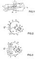
- FIG. 1 schematically represents the deflection of inclined light beams when crossing the window belonging to an optical device according to the invention.
- a generally afocal H window having a symmetry of revolution around an axis of revolution ar represented in phantom in Figure 1.
- the H window can be broken down functionally into a divergent lens DV located on the outside of the H window as encompassing the spherical external surface of the porthole H and into a converging lens CV situated on the internal side of the porthole H.
- the two lenses DV and CV have the same axis of symmetry ar and the same focal point F.
- A be the center of the diverging lens DV and B the center of the converging lens CV.
- G be the magnification of the afocal porthole H
- G F 1 / F 2 .
- magnification G As close as possible to 1.
- magnification of a window there are several ways, possibly combinable with each other, to make the magnification of a window closer to 1. For example, increase the radius of curvature of the exterior surface of the window, choose as the material of the window a lower index material, decrease the thickness of the window while respecting the minimum thickness imposed by mechanical constraints that the window will have to undergo in operational conditions during the flight of the aircraft.
- magnification G of the afocal is preferably close enough to 1 that, given the maximum value of the amplitude of the relative rotational movements between the axis of symmetry of window revolution and the line of sight of the optical sub-assembly, the parasitic deflection of a light beam passing through the window either low enough not to substantially disturb the operation of the optical equipment according to the invention.
- the magnification value G of the afocal porthole will be advantageously chosen so that the Resulting parasitic deflection of the light beam at the camera does not exceed half the step of the elementary detectors of the matrix.
- the magnification G is preferably chosen as close as possible to 1. From preferably, the magnification G of the afocal porthole is between 0.95 and 1. A magnification G whose value is not close enough to 1, will require often an additional correction for example of an electronic nature in the electronic processing part then associated with the subset optical.
- the two optical channels preferentially pass either through the same window or through two separate portholes with the same magnification.
- the line of sight of the optical sub-assembly is angularly offset with the follower cover, that is to say with the axis of symmetry of revolution of the porthole (s)
- a disharmony between the optical channels is thus avoided.
- the optical sub-assembly comprises an imaging device
- correction means electronics associated or integrated into the optical sub-assembly allowing electronically correct images.
- These means of correction electronics compensate for the gap between the axis of revolution of the window and the line of the optical sub-assembly.
- the parasitic deviation of the light beam crossing the afocal porthole results in a translation, on the sensor of the imaging device which is for example a camera, the image representing a portion of the observation space.
- this translation depends on the value of the angular difference between the axis of symmetry of porthole revolution and line of sight of the imaging device.
- this angular deviation can be known and is even measurable in real time by measuring the respective angular positions of a from the line of sight of the imaging device and from the cover follower.
- Electronic correction of sensor images is possible by real time provided that the frequency of the parasitic oscillations causing the parasitic deflection of the light beams passing through the window either sufficiently low compared to the reverse of the integration time of the sensor of the imaging device. For example, in the case of a digital camera, the correction can be reduced to a change of address on an image digitized.
- the afocal porthole has an outer surface which is spherical. If the porthole is a single-element porthole, that is to say made up of a single meniscus, the inside surface of the window cannot be a simple spherical surface concentric with the exterior surface, because then the window would be divergent at the instead of being afocal.
- the inner surface of the window which is then the only diopter internal of the window is preferably spherical not concentric with the surface external and / or aspherical and / or diffractive, that is to say comprising at least a network.
- An aspherical and / or diffractive interior surface allows also to correct or better correct certain optical defects of optical equipment according to the invention.
- a diffractive interior surface allows for example to include chromatic corrections in the window.
- the porthole is a two-part porthole, i.e. made up of two menisci, not all internal dioptres three be simple spherical surfaces concentric with the exterior surface, because then the window would be divergent instead of being afocal. All or part of these internal dioptres is preferably spherical not concentric on the surface external and / or aspherical and / or diffractive, depending on the type of equipment optics considered.
- the window can also be multi-element and then include more than three internal dioptres.
- the window is mono-element, the porthole therefore consists of a single meniscus.
- the surface exterior of the window is spherical, therefore has an optical power which is divergent.
- the only internal diopter of the window which is the internal surface of the window then has an optical power which is convergent of way to make the porthole afocal.
- the bi-element porthole has a more symmetrical break important than the single-element porthole, and therefore the aberrations and chromaticity defects are more difficult to correct with the window single element than with the single element porthole.
- the diverging and converging functional lenses constituting the globally afocal porthole can be brought very close each other, the magnification of the afocal window thus obtained can be then made sufficiently close to 1. This is why the window single element is preferred to the double port window.
- FIG. 2 schematically represents the sectional view of an example of optical equipment according to the invention comprising a single-element window.
- the single meniscus 10 constituting the afocal porthole H has an external surface 1 which is spherical and an internal surface 2 which is for example spherical not concentric with the external surface 1.
- the porthole H has an axis of symmetry of revolution ar.
- the porthole H is integrated into a follower hood 50 whose outer surface 51 has a continuity of shape with the outer surface 1 of the porthole H at their junction 52.
- the follower hood 50 preferably has a spherical shape which allows it to cover a wide angular field in space.
- the follower cover is movable in rotation around its center C which is also the center of curvature of the porthole H.
- An optical sub-assembly 80 is suspended from a support structure 60 by an anti-vibration suspension 70 which mechanically isolates the optical sub-assembly 80 by filtering the mechanical stresses coming from the supporting structure 60.
- the optical sub-assembly 80 has a line of sight LDV whose harmonization with the axis of symmetry of revolution ar is ensured for example by means of two mirrors M 1 and M 2 , the mirror M 2 being a fixed part of the optical sub-assembly 80 while the mirror M 1 , which is also mounted on the optical sub-assembly 80, is movable in rotation around the center C of curvature of the outer surface 1 of the window H, that is to say more precisely around an axis passing through the center C of curvature of the outer surface 1 of the window H in the absence of mechanical stresses exerted on the supporting structure 6 0.
- the optical sub-assembly 80 can be located partly outside the ball formed by the follower cover 50 with a spherical outer surface 51.
- the inner surface 2 of the meniscus preferably consists of a diopter which is on the one hand spherical not concentric with the external surface 1 window H and on the other hand diffractive.
- a diopter is made diffractive by example by adding a hologram.
- the radius of curvature R 1 is chosen equal to 200mm.
- the magnification values G of the afocal window obtained are given in the following table, for two values of thickness e equal to 20mm and 10mm:
- the window is connecting element, the porthole therefore consists of two menisci.
- the window consists of a divergent meniscus arranged towards the outside of the porthole and of a meniscus converging arranged towards the inside of the porthole, the two menisci being separated by an air knife or by a layer of glue.
- the window element With the window element, it is possible to obtain a magnification closer to 1 than with the single-element window.
- the bi-element porthole presents a rupture of greater symmetry than the single-element porthole, and therefore the aberrations and chromatism defects are more difficult to correct with the bi-element porthole than with the single-element porthole.
- a digital example subsequent will compare the outliers found previously for the single-element window with the aberrant gaps existing for a example of a twin window.
- Figure 3 schematically shows the sectional view of a example of optical equipment according to the invention comprising a window bieursment. For the sake of clarity in FIG. 3, no hatching is possible. represented.
- the essential difference with the case of Figure 2 previously described representing optical equipment according to the invention comprising a single-element porthole resides in the constitution of the porthole itself.
- the H afocal bi-element porthole consists of a first meniscus divergent 10 having an outer surface 1 which is spherical and a surface interior 2.
- the interior surface 2 may for example be spherical concentric with the outer surface 1, which allows the use as first meniscus 10 of a traditional classic porthole.
- H window also includes a second meniscus 30 having an outer diopter 3 and an internal diopter 4 which is the internal surface of the porthole H.
- a blade air 20 or a layer of glue 20 generally separates the two menisci 10 diverge and 30 converge.
- the rest of the optical equipment is similar to that described in Figure 2.
- the radius of curvature R 1 is chosen equal to 200mm.
- the radius of curvature R 2 is chosen to be 165mm because it is this value which gives substantially the best results, that is to say the smallest outliers.
- the thickness of each window is chosen equal to 10mm.
- the intruscal space ei is also the thickness of the air space 20 or the layer of glue 20.
- the radii of curvature R 3 and R 4 respectively of the diopters 3 and 4 of the second meniscus 30 are given in the following tables with outliers ⁇ .
- the same material constitutes each of the two menisci 10 and 30.
- the aberrant difference obtained for the single-element window is smaller than the one obtained for the bi-element porthole, which makes the porthole more interesting in this respect.
- the aberrant difference obtained for the single-element window is smaller than the one obtained for the bi-element porthole, which makes the porthole more interesting in this respect.
- the interior of the two menisci 10 and 30 of the window is preferably made of the same material for the two menisci 10 and 30.
- the correction of the chromatism especially when the optical equipment according to the invention operates in a spectral domain which is multiband, is facilitated.
- Drift depending temperature, the index of the material of the afocal porthole magnification close to 1, compensates for itself, which is not the case when the two menisci 10 and 30 are made of materials different.
- the outermost diopter of the outermost meniscus of the porthole is coated with a thin layer making a few micrometers of DLC (for diamond light carbon in terminology Anglo-Saxon) or boron phosphate, to make the porthole more resistant to erosion.
- DLC diamond light carbon in terminology Anglo-Saxon
- boron phosphate boron phosphate
- the spectral range of sensitivity of optical equipment preferably comprises part of the visible spectral domain and / or a part of the near infrared spectral range.
- This spectral range of sensitivity consists for example of the visible band or the band near infrared.
- the optical equipment is preferably a system of long range ground reconnaissance.
- the optical equipment is then integrated into an aircraft whose mission is for example to collect images on the terrestrial landscape of a neighboring country while not flying in space aerial from the neighboring country.
- This type of system has a very high resolution. high which makes it particularly sensitive to turbulence in the flow aerodynamics at the window.
- the optical equipment is mounted on an aircraft or integrated into an aircraft.
- the aircraft is preferably fast, that is to say that its speed in flight is comparable to that of an airplane, as opposed to slow type aircraft helicopter.
Landscapes
- Engineering & Computer Science (AREA)
- Physics & Mathematics (AREA)
- Chemical & Material Sciences (AREA)
- Combustion & Propulsion (AREA)
- General Engineering & Computer Science (AREA)
- General Physics & Mathematics (AREA)
- Optics & Photonics (AREA)
- Electromagnetism (AREA)
- Multimedia (AREA)
- Radar, Positioning & Navigation (AREA)
- Remote Sensing (AREA)
- Lenses (AREA)
Abstract
Description
- la figure 1 représente schématiquement la déviation de faisceaux lumineux inclinés lors de la traversée du hublot appartenant à un équipement optique selon l'invention ;
- la figure 2 représente schématiquement la vue en coupe d'un premier mode de réalisation préférentiel d'un équipement optique selon l'invention ;
- la figure 3 représente schématiquement la vue en coupe d'un deuxième mode de réalisation d'un équipement optique selon l'invention.


| ei | 30mm | 40mm |
| R3 | 1410mm | 437mm |
| R4 | -4400mm | 733mm |
| Δ | 6,8µm | 7,7µm |
| ei | 30mm | 40mm |
| R3 | 557mm | 269mm |
| R4 | 1100mm | 347mm |
| Δ | 10,3µm | 13,8µm |
Claims (16)
- Equipement optique destiné à être aéroporté comportant un sous-ensemble optique (80) protégé par un capot suiveur (50) mobile et par un hublot (H) solidaire du capot suiveur (50) et fixe par rapport au capot suiveur (50), caractérisé en ce que le hublot (H) est afocal, en ce que la surface extérieure (1) du hublot (H) est sphérique, en ce que la ligne de visée (LDV) du sous-ensemble optique (80) passe par le centre de courbure (C) de la surface extérieure (1) du hublot (H), et en ce que la surface extérieure (1) du hublot (H) présente avec la surface extérieure (51) du capot suiveur (50) une continuité de forme.
- Equipement optique destiné à être aéroporté comportant une structure porteuse (60), un sous-ensemble optique (80) ayant une ligne de visée (LDV) et étant à la fois suspendu à la structure porteuse (60) et mécaniquement isolé de la structure porteuse (60) par une suspension antivibratoire (70) filtrant les contraintes mécaniques, une enveloppe extérieure (50, H) protégeant le sous-ensemble optique (80) de l'environnement extérieur, l'enveloppe extérieure (50, H) comportant un capot suiveur (50) mobile par rapport à la structure porteuse (60) et un hublot (H) lequel permet une communication optique dans un domaine spectral donné entre le sous-ensemble optique (80) et l'extérieur, le hublot (H) étant entouré par le capot suiveur (50) et fixe par rapport au capot suiveur (50), caractérisé en ce que la surface extérieure (1) du hublot (H) est sphérique, en ce que la ligne de visée (LDV) du sous-ensemble optique (80) passe par le centre de courbure (C) de la surface extérieure (1) du hublot (H) en l'absence de contraintes mécaniques exercées sur la structure porteuse (60), en ce que la surface extérieure (1) du hublot (H) et la surface extérieure (51) du capot suiveur (50) présentent une continuité de forme entre elles au niveau de leur jonction (52) de manière à ne pas augmenter substantiellement les perturbations d'écoulement aérodynamique au niveau du hublot (H) quelle que soit la position relative du capot suiveur (50) et de la structure porteuse (60), et en ce que le hublot (H) comporte un ou plusieurs dioptres internes (2, 3, 4) fixes par rapport à la surface extérieure (1) du hublot (H), ledit ou lesdits dioptres internes (2, 3, 4) rendant le hublot (H) afocal.
- Equipement optique selon l'une quelconque des revendications précédentes, caractérisé en ce que le grossissement (G) du hublot (H) afocal est compris entre 0,95 et 1.
- Equipement optique selon l'une quelconque des revendications précédentes, caractérisé en ce que l'équipement optique comporte au moins deux voies optiques ayant des pupilles d'entrée séparées, et en ce que les deux voies optiques passent soit à travers le même hublot (H) soit à travers deux hublots (H) distincts mais de même grossissement (G).
- Equipement optique selon l'une quelconque des revendications précédentes, caractérisé en ce que le hublot (H) présente un axe de révolution (ar), en ce que le sous-ensemble optique (80) comporte un dispositif d'imagerie et des moyens de correction électronique des images compensant l'écart entre l'axe de révolution (ar) du hublot (H) et la ligne de visée (LDV) du sous-ensemble optique (80).
- Equipement optique selon l'une quelconque des revendications précédentes, caractérisé en ce que le hublot (H) est constitué d'un seul ménisque (10).
- Equipement optique selon la revendication 6, caractérisé en ce que la surface intérieure (2) du ménisque (10) consiste en un dioptre qui est d'une part sphérique non concentrique avec la surface extérieure (1) du hublot (H) et d'autre part diffractif.
- Equipement optique selon l'une quelconque des revendications 6 à 7, caractérisé en ce que, R2 étant le rayon de courbure du dioptre le plus interne (2) du hublot (H), R1 étant le rayon de courbure de la surface extérieure (1) du hublot (H) , e étant l'épaisseur du hublot (H) au niveau de son centre, N étant l'indice du matériau constituant ledit ménisque (10), la relation suivante est sensiblement vérifiée : R 2 = R 1 - e + e / N.
- Equipement optique selon l'une quelconque des revendications 1 à 5, caractérisé en ce que le hublot (H) est constitué d'un ménisque divergent (10) disposé vers l'extérieur du hublot (H) et d'un ménisque convergent (30) disposé vers l'intérieur du hublot (H), les deux ménisques (10 et 30) étant séparés par une lame d'air (20) ou par une couche de colle (20).
- Equipement optique selon la revendication 9, caractérisé en ce que le matériau constituant l'intérieur des deux ménisques (10 et 30) du hublot (H) est le même.
- Equipement optique selon l'une quelconque des revendications 6 à 10, caractérisé en ce que le matériau constituant l'intérieur du ou des ménisques (10, 30) est du saphir ayant un indice valant sensiblement N=1,7 ou du ZnS ayant un indice valant sensiblement N=2,2 ou du Silicium ayant un indice valant sensiblement N=3,4.
- Equipement optique selon l'une quelconque des revendications 6 à 11, caractérisé en ce que le dioptre le plus extérieur (1) du ménisque le plus extérieur (10) du hublot (H) est revêtu d'une couche mince faisant quelques micromètres de DLC ou de phosphate de bore.
- Equipement optique selon l'une quelconque des revendications précédentes, caractérisé en ce que le domaine spectral donné comprend une partie du domaine spectral visible et/ou une partie du domaine spectral proche infrarouge.
- Equipement optique selon l'une quelconque des revendications précédentes, caractérisé en ce que le capot suiveur (50) a une forme sphérique.
- Equipement optique selon l'une quelconque des revendications précédentes, caractérisé en ce que l'équipement optique est un système de reconnaissance terrestre de longue portée.
- Aéronef rapide caractérisé en ce qu'il comporte un équipement optique selon l'une quelconque des revendications précédentes.
Applications Claiming Priority (2)
| Application Number | Priority Date | Filing Date | Title |
|---|---|---|---|
| FR0013631A FR2815725B1 (fr) | 2000-10-24 | 2000-10-24 | Equipement optique destine a etre aeroporte |
| FR0013631 | 2000-10-24 |
Publications (2)
| Publication Number | Publication Date |
|---|---|
| EP1203978A1 true EP1203978A1 (fr) | 2002-05-08 |
| EP1203978B1 EP1203978B1 (fr) | 2007-12-19 |
Family
ID=8855689
Family Applications (1)
| Application Number | Title | Priority Date | Filing Date |
|---|---|---|---|
| EP20010402747 Expired - Lifetime EP1203978B1 (fr) | 2000-10-24 | 2001-10-23 | Equipment optique destiné à être aéroportés |
Country Status (4)
| Country | Link |
|---|---|
| EP (1) | EP1203978B1 (fr) |
| DE (1) | DE60131948T2 (fr) |
| ES (1) | ES2298207T3 (fr) |
| FR (1) | FR2815725B1 (fr) |
Cited By (2)
| Publication number | Priority date | Publication date | Assignee | Title |
|---|---|---|---|---|
| EP2385411A1 (fr) * | 2010-05-04 | 2011-11-09 | MBDA France | Procédé de correction de défauts d' aberrations au sein d'un dispositif optique d' observation d'un champ à travers une fenêtre |
| EP2533003A1 (fr) * | 2011-06-11 | 2012-12-12 | Diehl BGT Defence GmbH & Co.KG | Dispositif optique destiné au guidage du rayonnement d'une scène sur un détecteur |
Citations (3)
| Publication number | Priority date | Publication date | Assignee | Title |
|---|---|---|---|---|
| US3995933A (en) * | 1973-08-06 | 1976-12-07 | Hawker Siddeley Dynamics Limited | Optical scanning system for dirigible heads |
| US6091548A (en) * | 1997-10-01 | 2000-07-18 | Raytheon Company | Optical system with two-stage aberration correction |
| US6108133A (en) * | 1997-06-16 | 2000-08-22 | Sagem Sa | Stabilized multispectral sighting system |
-
2000
- 2000-10-24 FR FR0013631A patent/FR2815725B1/fr not_active Expired - Lifetime
-
2001
- 2001-10-23 ES ES01402747T patent/ES2298207T3/es not_active Expired - Lifetime
- 2001-10-23 EP EP20010402747 patent/EP1203978B1/fr not_active Expired - Lifetime
- 2001-10-23 DE DE2001631948 patent/DE60131948T2/de not_active Expired - Lifetime
Patent Citations (3)
| Publication number | Priority date | Publication date | Assignee | Title |
|---|---|---|---|---|
| US3995933A (en) * | 1973-08-06 | 1976-12-07 | Hawker Siddeley Dynamics Limited | Optical scanning system for dirigible heads |
| US6108133A (en) * | 1997-06-16 | 2000-08-22 | Sagem Sa | Stabilized multispectral sighting system |
| US6091548A (en) * | 1997-10-01 | 2000-07-18 | Raytheon Company | Optical system with two-stage aberration correction |
Cited By (7)
| Publication number | Priority date | Publication date | Assignee | Title |
|---|---|---|---|---|
| EP2385411A1 (fr) * | 2010-05-04 | 2011-11-09 | MBDA France | Procédé de correction de défauts d' aberrations au sein d'un dispositif optique d' observation d'un champ à travers une fenêtre |
| WO2011138518A1 (fr) * | 2010-05-04 | 2011-11-10 | Mbda France | Procédé de correction de défauts d'aberrations au sein d'un dispositif optique d'observation d'un champ à travers une fenêtre |
| FR2959829A1 (fr) * | 2010-05-04 | 2011-11-11 | Mbda France | Procede de correction de defauts d'aberrations au sein d'un dispositif optique d'observation d'un champ a travers une fenetre |
| US20130027783A1 (en) * | 2010-05-04 | 2013-01-31 | Mbda France | Process for correcting aberration defects within an optical device for observing a field through a window |
| US10180568B2 (en) | 2010-05-04 | 2019-01-15 | Mbda France | Process for correcting aberration defects within an optical device for observing a field through a window |
| EP2533003A1 (fr) * | 2011-06-11 | 2012-12-12 | Diehl BGT Defence GmbH & Co.KG | Dispositif optique destiné au guidage du rayonnement d'une scène sur un détecteur |
| US9207045B2 (en) | 2011-06-11 | 2015-12-08 | Diehl Bgt Defence Gmbh & Co. Kg | Optical device for guiding radiation from an object scene to a detector using an optical link and method for guiding radiation from the object scene to the detector by an optical link |
Also Published As
| Publication number | Publication date |
|---|---|
| FR2815725A1 (fr) | 2002-04-26 |
| DE60131948T2 (de) | 2008-12-04 |
| DE60131948D1 (de) | 2008-01-31 |
| FR2815725B1 (fr) | 2003-02-14 |
| ES2298207T3 (es) | 2008-05-16 |
| EP1203978B1 (fr) | 2007-12-19 |
Similar Documents
| Publication | Publication Date | Title |
|---|---|---|
| WO2000020913A1 (fr) | Dispositif optique pour viseur de casque comportant un miroir diffractif | |
| EP3044623B1 (fr) | Telescope a faibles deformations | |
| FR3060136A1 (fr) | Telescope compact presentant une pluralite de focales compense par des composants optiques aspheriques | |
| EP0066496B1 (fr) | Procédé de réalisation d'un filtre optique à microvolets et utilisation pour un indicateur cathodique aéroporté | |
| EP3336594B1 (fr) | Telescope compact presentant une pluralite de focales compense par des composants optiques aspheriques | |
| FR2944415A1 (fr) | Casque comprenant une detection de position de visiere et detection de position de casque associe | |
| CA2894615A1 (fr) | Microbarometre a soufflet et a transducteur interferometrique | |
| FR2833717A1 (fr) | Combinaison optique multichamp de type cassegrain | |
| EP3044622B1 (fr) | Support de miroir secondaire pour telescope | |
| EP3237860B1 (fr) | Systeme d'imagerie grand champ infrarouge | |
| EP1203978B1 (fr) | Equipment optique destiné à être aéroportés | |
| FR2944594A1 (fr) | Tete autodirectrice a deux voies de detection, et missile comportant une telle tete | |
| FR2863584A1 (fr) | Systeme optronique modulaire embarquable sur un porteur | |
| EP0130869A1 (fr) | Dispositif à imagerie vidéo, notamment pour autodirecteur | |
| BE898150A (fr) | Système de détection de rayonnement infrarouge. | |
| FR2764710A1 (fr) | Dispositif de visee stabilisee multispectral | |
| EP0900395B1 (fr) | Procede de correction des aberrations d'une lentille | |
| EP0099769B1 (fr) | Dispositif d'analyse d'un champ spatial pour la localisation angulaire d'un objet rayonnant | |
| EP0425365A1 (fr) | Dispositif optique de correction des défauts introduits par un hublot sphérique utilisÀ© hors d'axe | |
| FR2897165A1 (fr) | Optique grand angle dans le spectre infrarouge | |
| WO2022012824A1 (fr) | Nacelle optronique | |
| EP2625557B1 (fr) | Tête optique pour effectuer une mesure atmosphérique, systèmes et procédés de fabrication associés. | |
| FR2561003A1 (fr) | Dispositif optique rotateur d'image | |
| EP0610635B1 (fr) | Dispositif optique de calibration pour caméra thermique | |
| EP1079215B1 (fr) | Instrument de spectrométrie infrarouge à haute résolution |
Legal Events
| Date | Code | Title | Description |
|---|---|---|---|
| PUAI | Public reference made under article 153(3) epc to a published international application that has entered the european phase |
Free format text: ORIGINAL CODE: 0009012 |
|
| AK | Designated contracting states |
Kind code of ref document: A1 Designated state(s): AT BE CH CY DE DK ES FI FR GB GR IE IT LI LU MC NL PT SE TR |
|
| AX | Request for extension of the european patent |
Free format text: AL;LT;LV;MK;RO;SI |
|
| 17P | Request for examination filed |
Effective date: 20021029 |
|
| AKX | Designation fees paid |
Designated state(s): DE ES GB IT SE |
|
| GRAP | Despatch of communication of intention to grant a patent |
Free format text: ORIGINAL CODE: EPIDOSNIGR1 |
|
| GRAS | Grant fee paid |
Free format text: ORIGINAL CODE: EPIDOSNIGR3 |
|
| GRAA | (expected) grant |
Free format text: ORIGINAL CODE: 0009210 |
|
| AK | Designated contracting states |
Kind code of ref document: B1 Designated state(s): DE ES GB IT SE |
|
| REG | Reference to a national code |
Ref country code: GB Ref legal event code: FG4D Free format text: NOT ENGLISH |
|
| REF | Corresponds to: |
Ref document number: 60131948 Country of ref document: DE Date of ref document: 20080131 Kind code of ref document: P |
|
| REG | Reference to a national code |
Ref country code: SE Ref legal event code: TRGR |
|
| GBT | Gb: translation of ep patent filed (gb section 77(6)(a)/1977) |
Effective date: 20080313 |
|
| REG | Reference to a national code |
Ref country code: ES Ref legal event code: FG2A Ref document number: 2298207 Country of ref document: ES Kind code of ref document: T3 |
|
| PLBE | No opposition filed within time limit |
Free format text: ORIGINAL CODE: 0009261 |
|
| STAA | Information on the status of an ep patent application or granted ep patent |
Free format text: STATUS: NO OPPOSITION FILED WITHIN TIME LIMIT |
|
| 26N | No opposition filed |
Effective date: 20080922 |
|
| PGFP | Annual fee paid to national office [announced via postgrant information from national office to epo] |
Ref country code: DE Payment date: 20201013 Year of fee payment: 20 Ref country code: IT Payment date: 20201013 Year of fee payment: 20 Ref country code: SE Payment date: 20201012 Year of fee payment: 20 Ref country code: GB Payment date: 20201014 Year of fee payment: 20 Ref country code: ES Payment date: 20201103 Year of fee payment: 20 |
|
| REG | Reference to a national code |
Ref country code: DE Ref legal event code: R071 Ref document number: 60131948 Country of ref document: DE |
|
| REG | Reference to a national code |
Ref country code: GB Ref legal event code: PE20 Expiry date: 20211022 |
|
| REG | Reference to a national code |
Ref country code: SE Ref legal event code: EUG |
|
| REG | Reference to a national code |
Ref country code: ES Ref legal event code: FD2A Effective date: 20220128 |
|
| PG25 | Lapsed in a contracting state [announced via postgrant information from national office to epo] |
Ref country code: GB Free format text: LAPSE BECAUSE OF EXPIRATION OF PROTECTION Effective date: 20211022 |
|
| PG25 | Lapsed in a contracting state [announced via postgrant information from national office to epo] |
Ref country code: ES Free format text: LAPSE BECAUSE OF EXPIRATION OF PROTECTION Effective date: 20211024 |
|
| P01 | Opt-out of the competence of the unified patent court (upc) registered |
Effective date: 20230529 |