EP1202811B1 - Beeinflussung von partikeln in flüssigen medien - Google Patents
Beeinflussung von partikeln in flüssigen medien Download PDFInfo
- Publication number
- EP1202811B1 EP1202811B1 EP00946174A EP00946174A EP1202811B1 EP 1202811 B1 EP1202811 B1 EP 1202811B1 EP 00946174 A EP00946174 A EP 00946174A EP 00946174 A EP00946174 A EP 00946174A EP 1202811 B1 EP1202811 B1 EP 1202811B1
- Authority
- EP
- European Patent Office
- Prior art keywords
- particles
- chamber
- ultrasonic
- standing wave
- ultrasonic vibration
- Prior art date
- Legal status (The legal status is an assumption and is not a legal conclusion. Google has not performed a legal analysis and makes no representation as to the accuracy of the status listed.)
- Expired - Lifetime
Links
Images


Classifications
-
- B—PERFORMING OPERATIONS; TRANSPORTING
- B03—SEPARATION OF SOLID MATERIALS USING LIQUIDS OR USING PNEUMATIC TABLES OR JIGS; MAGNETIC OR ELECTROSTATIC SEPARATION OF SOLID MATERIALS FROM SOLID MATERIALS OR FLUIDS; SEPARATION BY HIGH-VOLTAGE ELECTRIC FIELDS
- B03C—MAGNETIC OR ELECTROSTATIC SEPARATION OF SOLID MATERIALS FROM SOLID MATERIALS OR FLUIDS; SEPARATION BY HIGH-VOLTAGE ELECTRIC FIELDS
- B03C5/00—Separating dispersed particles from liquids by electrostatic effect
- B03C5/02—Separators
- B03C5/022—Non-uniform field separators
- B03C5/026—Non-uniform field separators using open-gradient differential dielectric separation, i.e. using electrodes of special shapes for non-uniform field creation, e.g. Fluid Integrated Circuit [FIC]
-
- B—PERFORMING OPERATIONS; TRANSPORTING
- B03—SEPARATION OF SOLID MATERIALS USING LIQUIDS OR USING PNEUMATIC TABLES OR JIGS; MAGNETIC OR ELECTROSTATIC SEPARATION OF SOLID MATERIALS FROM SOLID MATERIALS OR FLUIDS; SEPARATION BY HIGH-VOLTAGE ELECTRIC FIELDS
- B03C—MAGNETIC OR ELECTROSTATIC SEPARATION OF SOLID MATERIALS FROM SOLID MATERIALS OR FLUIDS; SEPARATION BY HIGH-VOLTAGE ELECTRIC FIELDS
- B03C5/00—Separating dispersed particles from liquids by electrostatic effect
- B03C5/02—Separators
- B03C5/022—Non-uniform field separators
- B03C5/028—Non-uniform field separators using travelling electric fields, i.e. travelling wave dielectrophoresis [TWD]
Definitions
- This invention relates to the manipulation of particles in liquid media.
- Another area of increasing importance is the promotion of desired reactions, usually on a microscopic scale, by bringing reactants into contact, the reactants either being in particulate form themselves or one or more of them being in the form of some form of particle having associated with it a generally non-particulate reactant.
- particle is used to include biological cells, bacteria, viruses, parasitic microorganisms, DNA, proteins, biopolymers, non-biological particles, or any other particle which may be suspended in a liquid, in which dielectrophoretic and ultrasonic forces can be induced. It also applies to chemical compounds or gases dissolved or suspended in a liquid, where dielectrophoretic and ultrasonic forces can be induced. It further includes any particles which can be attached to larger particles, in which .dielectrophoretic and ultrasonic forces can then be induced.
- the geometric dimensions of the ultrasound radiator 8 are selected so that the place where the chamber is positioned a standing wave is generated, the rate of oscillation of which is directed over the whole cross-section of the chamber along the radius in the direction toward the axial electrode or away from it. In this way, the diameter of the chamber does not exceed the length of the ultrasonic wave", then goes on to state "The oscillatory frequency of the sources 16 and 17 are selected to be the same and their phases synchronised using synchroniser 18".
- Sources 16 and 17 refer to the signal sources for the ultrasound and dielectrophoresis, and as such the signals utilised for both the ultrasound and dielectrophoresis are at the same frequency with their phases linked.
- a disadvantage of such an arrangement is that the constraints imposed on the ultrasound frequency range (e.g. 1 to 6 MHz) by the chamber size also restricts the dielectrophoretic response correspondingly to a very small range.
- the constraints imposed on the ultrasound frequency range (e.g. 1 to 6 MHz) by the chamber size also restricts the dielectrophoretic response correspondingly to a very small range.
- a frequency range extending from at least 1 kHz to 10 MHz is required.
- a method of manipulating particles comprising subjecting particles suspended in a liquid to a moving ultrasonic standing wave and to a varying electrical field capable of generating a dielectrophoretic force on the particles.
- apparatus for treating particles suspended in a liquid comprising a chamber, means for feeding suspended particles into and out of the chamber, an electrode array on at least one wall of the chamber, means for applying to the electrode array an alternating electrical potential whereby to generate in suspended particles adjacent to the array a dielectrophoretic force, and means for subjecting the liquid in the chamber to a moving ultrasonic standing wave.
- the arbitrary constants a and b may be made the same, i.e. the dielectrophoretic force acting on a particle can be made greater than, equal to, or less than the ultrasonic force exerted on that particle. Because both of the forces are dependent upon the particle volume, variations in volume do not affect the ability to apply a balance of ultrasonic and dielectrophoretic forces or to make one exceed the other. Accordingly, the ability to manipulate the particles becomes effectively independent of their volume, and this enables much enhanced manipulations to be carried out. In particular, the relative size of particles has no effect on their ability to be separated using techniques involving the combined application of ultrasonic and dielectrophoretic forces to them.
- the dielectrophoretic and ultrasound forces may be applied simultaneously, but in addition they may be applied sequentially to secure appropriate movement of the particles.
- ultrasonic irradiation may be used in the absence of any dielectrophoretic force being applied to the particles to move particles in suspension in a liquid medium in a desired fashion.
- ultrasonic irradiation is first used to move particles to be manipulated from a first liquid medium in which they are suspended into a second liquid medium, the conductivity, dielectric permittivity, pH and other physico-chemical properties of the second liquid medium being appropriate for enabling the generation of appropriate dielectrophoretic force on the individual particles.
- particles which have been subjected to dielectrophoretic separation may be subjected to ultrasound in order to cause the particles effectively to concentrate together, or even sediment out from the liquid medium in which they have been suspended during the dielectrophoretic separation.
- This concentration process may be used to increase the efficiency of practical separation apparatus.
- the particles in order to generate adequate dielectrophoretic forces, the particles must be located in close proximity to electrical field-generating electrode arrays. Conventionally, this is often achieved simply by using gravity to allow particles in suspension to congregate adjacent electrode surfaces, but this can take a substantial time, particularly if the relative densities of the particles and the suspending liquids are close.
- ultrasonic manipulation particles suspended in a liquid may be moved into close proximity with a suitable electrode array rapidly. By using a moving standing ultrasonic wave, it is also possible to move particles across an electrode array.
- the present invention provides apparatus for treating particles suspended in a liquid medium including a chamber, means for feeding suspended particles into and out of the chamber, an electrode array on at least one wall of the chamber, means for applying to the electrode array an alternating electrical potential whereby to generate in suspended particles adjacent the array a dielectrophoretic force, and means for subjecting the liquid in the chamber to a moving ultrasonic standing wave.
- an appropriately dimensioned treatment chamber i.e. one which is narrow relative to the wavelength of the ultrasound used, it is possible to make particles move towards the walls of the chamber on which electrode structures are located.
- a volume of liquid having suspended in it particles requiring separation according to some appropriate criterion can be introduced into a chamber, the chamber then subjected to ultrasound to move the particles to the walls of the chamber, and thereafter the particles on the walls which bear electrode arrays can be separated using a combination of ultrasonic forces and dielectrophoretic forces exerted on them.
- Dielectrophoretic forces are inherently short-range in their effect and so either a significant time must be allowed for particles to sediment on to the electrodes, or the apparatus must be arranged so that the particles are within a short distance of the electrodes, typically no more than 300 ⁇ m, and preferably no more than 100 ⁇ m.
- Ultrasound can be utilised to move cells rapidly on to the electrodes at chamber walls to facilitate efficient dielectrophoretic separation subsequently; for the conditions where the chamber height is in the order of the wavelength of the sound wave, cells start to move toward the walls of the chamber; (the exact dimensions will depend on the manner in which the ultrasound is applied and also the acoustic properties of the chamber walls).
- the wavelength of ultrasound in water at 20°C, for an ultrasound frequency range of 500kHz to 10MHz, is around 150 to 3000 microns, so the dielectrophoresis chamber may be an order of magnitude larger than a chamber employing no ultrasound.
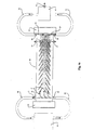
- this shows diagrammatically a separation unit consisting essentially of a central separation chamber 1 which is in liquid communication with an input chamber 2 and an output chamber 3 having two sample output ports 4 and 5.
- a separation unit consisting essentially of a central separation chamber 1 which is in liquid communication with an input chamber 2 and an output chamber 3 having two sample output ports 4 and 5.
- ultrasonic transducers 10, 11 At each end of the chamber 1 are located ultrasonic transducers 10, 11 and likewise two ultrasonic transducers 12 and 13 are located at each end of the input chamber 2 which is mounted transversely with respect to the chamber 1.
- Electrodes array On the walls of chamber 1 is an array of castellated electrodes of appropriate size and spacing to enable dielectrophoretic forces to be exerted on particles within the chamber 1 when appropriate alternating electrical potentials are applied to the electrodes.
- the electrode array is illustrated diagrammatically in magnified scale at 20 in Figure 1.
- means for feeding a liquid with particles suspended in it to the input chamber 2, through the separation chamber 1 and then through the output chamber 3 are omitted, as are any of the electrical connections necessary to drive the transducers and to apply the alternating voltages to the electrode array illustrated at 20. Also not shown in the diagram are means for selectively opening outlets 4 and 5 from the outlet chamber 3.
- a sample of liquid containing suspended particles is placed in chamber 2.
- an ultrasonic frequency standing wave may be set up within the volume of liquid in chamber 2.
- This standing wave causes the particles either to move to areas of low ultrasonic pressure or to areas of high ultrasonic pressure depending on their relative acoustic properties and accordingly causes the particles to group together in bands.
- the individual particles can be considered as larger group particles which can be sedimented and controlled more easily. They may then be moved in a controlled manner, by sedimenting them from the suspending liquid, in chamber 2 and re-suspending them into the liquid of chamber 1.
- a liquid fills all of chambers 1, 2 and 3 and output point 4, 5.
- the transducers 10 and 11 are driven with an appropriate signal to generate an ultrasonic standing wave which moves along the length of the chamber from left to right.
- the vertical dimension (as shown in Figure 1) of chamber 1 is in the range of the wavelength of the ultrasound produced by transducers 10 and 11, the particles are pushed towards the walls of the chambers 1 on which the electrode array 20 is located.
- the particles On reaching the end of chamber 1, the particles reach a barrier preventing them from passing any further.
- This barrier may be of a thin material and of similar acoustic properties to that of the suspending medium (to thus present minimal disruption to the ultrasonic field), such as an adapted thin glass microscope coverslip.
- the particles will then start sedimenting toward collection ports 4 and 5.
- a switching valve system in the form of a flap. This directs the particles toward either port 4 or 5 for collection. In this instant, particles are directed toward port 4.
- output port 4 is closed and output port 5 opened and the electrical signals applied to transducers 10 and 11 and to electrode array 20 may be varied to release the previously held particles and accordingly enable them to be collected from port 5.
- suitable collection receptacles such as bijou bottles are located, the particles will sediment into them. Particles of one type will sediment at port 4 and particles of a different type will sediment at port 5.
- the apparatus shown in Figure 1 may be used sequentially to treat a number of batches of liquid each containing both types of particle to produce two containers, one of which contains a desired particle type(s) and the other of which contains the undesired particle types.
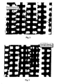
- FIGs 2 and 3 are photographs showing the electrode array 20, in each case showing just four individually castellated electrode strips, and wherein the illumination has been adjusted to show the presence of yeast cells as pearl grey areas against the clear liquid background and between the darker grey castellated electrodes.
- Figure 2 shows a stage in the procedure where a sample of suspended yeast cells, some alive and some dead, has been introduced into the chamber and subjected to both ultrasound and dielectrophoretic forces.
- the effect of the ultrasound is to group the cells into bands parallel to the longitudinal extension of the castellated electrodes.
- the cells, once in these bands are subjected to dielectrophoretic forces and these may be adjusted so that the cells are moved to be held by the array.
- the alternating electrical potential applied to the electrodes is a potential of three volts oscillating at a frequency of 500 kHz in a medium of conductivity 50 ⁇ s/cm.
- the greyish bands of cells concentrate between the castellated electrodes and held by positive DEP forces.
- the alternating voltage applied to the electrode array 20 is changed to one of e.g. twelve volts peak to peak and a frequency of six MHz.
- This causes live yeast cells to be held stationary relative to the electrode array rather more strongly than dead yeast cells.
- the standing ultrasonic wave may be caused to travel away from chamber 2 and towards chamber 3 sweeping dead yeast cells along the chamber as it does so. These accordingly arrive in chamber 3 and can be removed.
- the live yeast cells are held in the electrode array, from which they can subsequently be removed when desired by changing the voltage and frequency applied to that electrode array, whereafter they may be collected on output chamber 3 likewise.
- Figure 3 shows the ultrasound "pulling" at, and moving the cells held by the electrodes by positive DEP forces, as is shown. This clearly shows the level of control attainable by utilising the ultrasonic and dielectrophoretic forces in combination, where particles held by strong positive DEP, by marginally differing values, can be discriminated and separated. This level of control is not only desirable, but has much application.
- a quantity of particles in suspension may be introduced from chamber 2 into chamber 1 and brought e.g. by ultrasonic sedimentation and movement to the electrode region.
- the particles in liquid suspension may then be moved backwards and forwards along chamber 1 using ultrasonic standing waves generated by transducers 10 and 11 and this combined with appropriate signal application to the electrode array 20 may enable particles to be selectively held when the travelling wave is moving in one direction and released when moving in the other.
- one particle type may be moved towards one end of the chamber 1 and other particle types to the other end of chamber 1.
- the apparatus may be operated continuously with two separated streams of particles being collected at locations at either end of chamber 1.
- this process may also be achieved by introducing particles by means of fluid flow into chamber 1, when chamber 2 is not required. This can be advantageous where the particles, for example, are already suspended in a medium of the desired conductivity and re-suspension is not required.
- the movement of the standing wave may be achieved by a number of known electronic techniques; phase sweeping, frequency sweeping or frequency offsetting of the relative signals applied to the transducers 10 and 11, or alternatively mechanically by changing the chamber dimensions.
- the standing ultrasonic wave may be generated by a single transducer and a reflector, or two or more transducers.
- the ultrasound may be used to move the particles toward the centre of the chamber, instead of towards the chamber walls.
- a higher ultrasonic frequency for a chamber of unchanged dimensions
- increased chamber height may be utilised to meet this objective.
- the chamber may be made of a material of low Young's modulus, such as a soft plastic.
- the chamber is preferably made of a material of a high Young's modulus, such as glass.
- the chamber walls may be vibrated with this purpose in mind, either utilising the transducers used for producing the standing wave in the chamber, utilising an external transducer, or manufacturing the walls of the chamber from a piezoelectric material.
- Vibration of the chamber walls may also be beneficial after a separation is completed, whereby very high power ultrasound can be utilised for the purpose of damaging and/or disintegrating and/or dissolving the particles left in the middle of the chamber and/or on the chamber walls. Ultrasonic cleaning and/or sterilisation of the chamber after dielectrophoretic separation can thus be achieved.
- One or more of these variants may be used in combination, such that, for example, the ultrasonic frequency may be changed, with one separation being undertaken with the particles primarily formed in the centre of the chamber and moved by the ultrasound, followed by a second separation being undertaken with the particles primarily forming on the walls of the chamber and there moved by the ultrasound standing wave.
- the ultrasonic frequency may be changed, with one separation being undertaken with the particles primarily formed in the centre of the chamber and moved by the ultrasound, followed by a second separation being undertaken with the particles primarily forming on the walls of the chamber and there moved by the ultrasound standing wave.
- the ultrasonic frequency may be changed, with one separation being undertaken with the particles primarily formed in the centre of the chamber and moved by the ultrasound, followed by a second separation being undertaken with the particles primarily forming on the walls of the chamber and there moved by the ultrasound standing wave.
- utilising one or more variants is beneficial for complex separations.
- Acoustic impedance can be considered as an analogue of electrical impedance and thus the principles of radio frequency impedance matching can be applied, as is known. Using these principles, it was calculated in the order of 92% of the energy transmitted by a PZT transducer is reflected back at the water interface and dissipated as heat.
- ⁇ quarter wave
- aluminium because its acoustic impedance is between that of PZT and water and using polymethyl methacrylate (PMMA) because it is between that of aluminium and water. So essentially the impedance of the aluminium is matched to the PZT, the PMMA to the aluminium, and then the PMMA to the water. This reason for the ⁇ /4 thickness or odd multiples of (i.e. ⁇ /4, 3 ⁇ /4, 5 ⁇ /4, etc.) is well-known.
- chamber 1 and chamber 2 of Figure 1 may alternatively be implemented with a single transducer and reflector for each, with two opposing transducers not being required, but preferred. When two opposing transducers are used, the reflections at the ends of the chamber are detrimental.
- impedance matching for combined ultrasound and dielectrophoretic separations is therefore preferred.
- the benefits of using impedance matching not only applies to phase sweeping, but includes all other methods of electrical and mechanical control of the standing wave, and when one or more transducers is used.
- a vertical chamber may instead be used for chamber 2, rather than the horizontally mounted chamber which is generally preferred.
- the use of a vertical chamber typically results in particles having to move greater distances. It has been found that when moving bands of particles over greater distances, the breaking up of these bands is more likely to occur, with sedimentation efficiencies effected.
- Sedimentation in chamber 2 can be achieved by either utilising a moving standing wave, combination of a moving standing wave and a stationary standing wave, or by pulsing the signals applied to the ultrasonic transducers 12, 13.
- the pulsing of the signals results in the standing wave momentarily being removed, with the particles sedimenting but also dispersing from their bands.
- the process of applying the standing wave, momentarily removing it, then re-applying i.e. the result of pulsing of the signal), allows the particles to sediment in a controlled manner.
- the chamber be circular in cross-section, thus to form a barrel shaped chamber. Improved sedimentation time and efficiency result. Preferential conditions can further be improved by using a Bessel sound field.
- a Bessel sound field By making the region of the ultrasonic transducer which is excited equal to 2/3 of the diameter of the chamber, and also (not necessary, but preferred) the diameter of the transducer which is excited equal to three times the thickness of the transducer, a Bessel sound field is generated, producing maximum pressure in the centre of the chamber and minimal pressure at the chamber wall, as is well-known. This concentrates the particles toward the central region of the chamber, allowing further improved sedimentation and control.
- Particles in chamber 1 of Figure 1 may also be separated by applying the principles of field flow fractionation (FFF) combined with dielectrophoresis (DEP).
- FFF field flow fractionation
- DEP dielectrophoresis
- ultrasound is used to transport the particles rather than bulk fluid flow.
- Bulk fluid flow and ultrasound may also be used in combination with dielectrophoresis.
- Changes in the suspending medium properties in chamber 1 can have a marked effect on particle separations and efficiency.
- fluid flow when performing a separation in chamber 1 of combined ultrasound and DEP, it may also be beneficial to introduce fluid flow.
- a small amount of fluid flow may be introduced along the chamber to stabilise the properties of the suspending medium.
- chamber 2 When chamber 2 is used to re-suspend particles from an unknown suspension medium into chamber 1 which contains known medium, the particles are likely to bring with them additional items which can change the suspending medium's physico-chemical properties, for example excess ions, which can change the conductivity.
- Fluid flow may also be introduced in chamber 1 as an additional force in combination with ultrasound and dielectrophoresis.
- fluid flow used in conjunction with chamber 2 may also be beneficial for continuous separation.
- This method has certain advantages over a batch process, in which 10 ml of suspended particles is repeatedly introduced the particles sedimented into chamber 1 and the fluid removed and replaced with another suspension.
- chamber 2 can remain filled with fluid and suspended particles continuously flowed into this chamber and sedimented with ultrasound.
- a number of options are available when it is desired to perform combined ultrasonic and dielectrophoretic separations with the particles first formed in the centre of the chamber, and then, at a later stage, the particles formed on the walls of the chamber, or vice versa.
- One option is to change the dimensions of the chamber, but more preferable is to change the ultrasonic frequency to achieve this.
- the efficiency of the transducer may be reduced which would enable it to be used over a wider frequency range.
- the same high efficiency transducer may be used, but the harmonics of the transducer excited. For example, a 1 MHz transducer typically has harmonics at just over 3 MHz and 5 MHz.
- the same transducer may be used at these frequencies, allowing particles to be moved toward the centre or toward the walls of a chamber. It may also be beneficial to not only apply differing frequencies to the transducers at different points in time, but also to apply a combined frequency signal to the transducers at the same time.
- the signal applied to one of the transducers can be considered as the reference and the other signal varied, i.e. phase or frequency swept, or frequency offset, relative to this, in order to move the standing wave and thus particles.
- both signals may be varied relative to each other at the same time. The result is either particles moving toward the centre of the chamber from both ends (at the same time), or the movement of particles from the centre toward either end. The same effect may also be achieved mechanically. Such an approach can be particularly valuable when applying a variation of FFF (field flow fractionation).
- FFF field flow fractionation
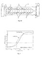
- Figure 4 shows a device based on negative dielectrophoretic (DEP) forces for separation of two or more particle types.
- Figure 4A shows a chamber 30, typically comprising upper and lower glass substrates sandwiches together to leave a central gap of 100 to 300 microns.
- the chamber has a first pair of cross flow ports 32, 34 at an input end, and a second pair of cross flow ports 36, 38 at an output end. At the output end and upstream of the ports 36, 38 are two output ports 40, 42 at opposite sides of the chamber.
- an ultrasonic transducer 44, 46 operable to generate in the chamber a standing wave having nodes and anti-nodes indicated by the thick bars 48; the standing wave is arranged to move from left to right in the figure.
- the moving standing wave between transducers 44 and 46 may remove the particles from this cross fluid flow suspension and divert them along the chamber as shown by the arrow I'.
- Figure 4B shows the DEP electrodes 50 arranged in pairs along opposite sides of the chamber 30 at angles to the direction of flow to form a fishbone array.
- the electrodes extend at an angle across the direction of movement of the particles caused by the ultrasonic field, except for a central strip which has no electrodes.
- Figure 4C shows that electrodes of each pair are connected to opposite sides of an AC signal source 52 by connectors 54, 56. The connections form a mirror image across the array so that in all of the electrode pairs, the upstream electrode is connected to the same side of the source 52.
- the gap between individual electrode pairs is significantly less than it is between adjacent electrode pairs, as is seen for the electrodes 50 shown in Figure 4b, 4c and 4d.
- 40 ⁇ m wide electrodes 40 ⁇ m gap between the electrode pairs and 250 ⁇ m between adjacent pairs.
- a strong (relative) negative DEP force will be generated in the region between the electrode pairs.
- the gap is significantly greater and so a very much weaker negative DEP force is generated. The result of this is that as particular particle passes along the chamber, it will see the regions between the electrode pairs as being "walls", or very strong barriers of negative DEP, repelling it from these regions. With the electrodes slanted at an angle toward the centre of the chamber, the particle will be guided toward this region in the centre of the chamber by the barriers of negative DEP.
- a pair of angle barriers 60, 62 arranged to divert particles near the edges of the chamber 30 out through the ports 40, 42.
- the barriers are of a material of similar acoustic impedance to water, for example glass, and are thin in comparison with the wavelength of the applied ultrasonic wave so as to cause minimal disturbance to the moving standing wave.
- TWD traveling wave dielectrophoresis
- the barrier may be similar to that of 60, 62, for example, of thin glass or thin polyimide film; a typical thickness of 100 ⁇ m.
- FIG. 4E illustrates schematically the entire flow system.
- An input chamber 64 contains a suspension of type S and type W particles to be separated and is connected by pipe 66, 68 to the cross flow ports 32, 34.
- an optional secondary DEP separation and purification stage 17 connected by pipe 72, 74 to the cross flow ports 36, 38 and having an output port 76. If a secondary separation is not essential, then port 38 can constitute a direct output port.
- negative DEP force in a separation process is particularly effective when particles in high concentration are to be separated, for example at a concentration of 100 million particles per millilitre or more, and when a large volume of suspension is to be processed, typically tens of millilitres of suspension.
- the implementation is particularly versatile in that it allows for continuous separation to be performed.
- the suspending medium properties of the cross fluid flow between ports 32 and 34 may be different to that of the central chamber 30. Additionally, the suspending medium properties of the cross fluid flow between ports 36 and 38 may be different again from both that of the chamber 30 and between ports 32 and 34. This allows, for example, particles suspended in an unknown fluid to be introduced into chamber 64.
- This suspension is then flowed across chamber 30 between ports 32 and 34.
- the conductivity and other physico-chemical properties of the suspending medium in chamber 30 are chosen to be preferable for the separation of these particles.
- the particles in the cross fluid flow between ports 32 and 34 are removed and taken along the chamber in the ultrasonic standing wave. As the particles pass over the electrodes 50, those of the desired type are enriched in the centre of the chamber and pass to the end. When these particles reach the end of the chamber, they are removed from the chamber by the cross fluid flow between ports 36 and 38, and passed into chamber 70.
- the conductivity and other physico-chemical properties of the suspending medium in chamber 70 and thus also the fluid flowing between ports 36 and 38 is chosen to be preferable for a secondary DEP separation stage, such as a TWD (travelling wave dielectrophoresis).
- a secondary DEP separation stage such as a TWD (travelling wave dielectrophoresis).
- the flow rate between ports 32 and 34 can be varied and adjusted to compensate for differing concentrations of particles in the solution contained in chamber 64, and so essentially a vast range of particle concentrations can be handled from chamber 64, whilst the concentration of the particles in chamber 30 may remain constant.
- the rate at which the standing wave travels along the chamber can also be adjusted in line with this.
- ports 32 and 34, and/or ports 36 and 38 may be moved from those shown in Figure 4e so that the cross fluid flow between the port pairs may be at an angle relative to the length of chamber 30 and the ultrasonic standing wave. This can be beneficial to the efficiency of introducing and/or removing particles from the ultrasonic field in chamber 30.
- the volume of fluid in this system may also be fixed and enclosed in that fluid flowing between ports 32 and 34 and chamber 64 is fixed, as is the fluid flowing between ports 36 and 38 and chamber 70.
- Figure 4c shows electrodes of each pair connected to opposite sides of an AC signal source. Additionally, the electrode of the adjacent pair is also connected to the opposite side of the AC signal source, as shown in Figure 4c.
- the electrodes may alternatively be connected so that no DEP force is generated between the electrodes of adjacent pairs. This is achieved by connecting the electrodes such that the electrode of the adjacent pair is connected to the same side of the AC signal source. They will thus be at the same potential and no DEP force will result between them.
- the dielectric properties of one or more of the particles being separated may be altered to achieve a desired separation. This may include factors such as changing the physiological properties of the particles, stressing the particles, changing the temperature of the sample, adding chemicals to the particle suspension, attaching additional particles such as antibodies or proteins, or, more particularly, for biological particles, the selective killing or damaging of specific particles to thus enhance a separation, an example of which may be the stressing or lysing of red blood cells.
- Figure 5 shows dielectrophoresis spectra expected for human red blood cells (rbc's) and T-lymphocytes white blood cells (wbc's) in a medium of conductivity 200pS/cm.
- the T-lymphocyte spectra is shown as a dotted line, whilst the red blood cell (rbc) spectra is shown as a solid line.
- the preferred case is where one of the particle types is held by a positive DEP force, whilst the other feels a negative DEP force being pushed away from the electrodes.
- the frequency which would preferably be used for separating these two particles is indicated as F1, approximately 130kHz.
- the ultrasound frequency (typically 1 to 6 MHz - corresponding log value 6 to 6.8) is vastly different to the DEP preferred frequency 130 kHz, F1 (log value 5.1). Different frequencies for the ultrasound and DEP are preferred.
Claims (15)
- Verfahren zum Beeinflussen von Teilchen, wobei in einer Flüssigkeit suspendierte Teilchen einer Ultraschallschwingung und einem variierenden elektrischen Feld, das eine dielektrophoretische Kraft auf die Teilchen ausüben kann, unterworfen werden, dadurch gekennzeichnet, daß die Ultraschallschwingung in Form einer sich bewegenden stehenden Ultraschallwelle angewandt wird.
- Verfahren nach Anspruch 1, bei dem die Ultraschallschwingung und das variierende elektrische Feld zu verschiedenen Zeiten angewandt werden.
- Verfahren nach Anspruch 1 oder 2, bei dem eine stationäre stehende Ultraschallwelle angewandt wird, gefolgt von einer sich bewegenden stehenden Ultraschallwelle.
- Verfahren nach Anspruch 1 oder 2, bei dem eine sich bewegende stehende Ultraschallwelle angewandt wird, gefolgt von einer stationären stehenden Ultraschallwelle.
- Verfahren nach Anspruch 2, bei dem die Ultraschallschwingung zu Beginn angewandt wird, um die Teilchen von einem flüssigen Medium in ein zweites flüssiges Medium zu bewegen.
- Verfahren nach Anspruch 2, bei dem die Ultraschallschwingung angewandt wird, um die Teilchen in eine große Nähe zu einer ein elektrisches Feld erzeugenden Elektrodenanordnung zu bewegen.
- Verfahren nach Anspruch 2, bei dem die Ultraschallschwingung angewandt wird, um die Teilchen in das Zentrum des flüssigen Mediums zu bewegen.
- Verfahren nach Anspruch 1, bei dem die Ultraschallschwingung und das variierende elektrische Feld gleichzeitig angewandt werden.
- Verfahren nach Anspruch 8 zum Trennen von zwei Arten von Teilchen, wobei eine sich bewegende stehende Ultraschallwelle derart angewandt wird, daß sich beide Arten von Teilchen durch eine Elektrodenanordnung bewegen, und an die Elektrode ein elektrisches Signal bei einer solchen Frequenz angelegt wird, daß eine Art der Teilchen eine starke negative DEP-Kraft erfährt und in einen Bereich der Elektrodenanordnung abgelenkt wird, während die zweite Art der Teilchen eine schwache negative DEP-Kraft erfährt und relativ unbeeinflusst ist, wenn sie sich durch die Anordnung bewegt.
- Verfahren nach einem der vorstehenden Ansprüche, das ferner die Anwendung einer Fluidströmung umfasst, um die Beeinflussung der Teilchen zu unterstützen.
- Verfahren nach einem der vorstehenden Ansprüche, worin die Ultraschallschwingung und das variierende elektrische Feld verschiedene Frequenzen aufweisen.
- Verfahren nach einem der vorstehenden Ansprüche, worin die Ultraschallschwingung und das variierende elektrische Feld in verschiedenen Ebenen angewandt werden.
- Vorrichtung zum Behandeln von Teilchen, die in einer Flüssigkeit suspendiert sind, mit einer Kammer, einer Einrichtung zum Zuführen von suspendierten Teilchen in die Kammer und aus dieser heraus, einer Elektrodenanordnung an mindestens einer Wand der Kammer, einer Einrichtung zum Anlegen einer elektrischen Wechselspannung an die Elektrodenanordnung, wodurch in suspendierten Teilchen in der Nähe der Anordnung ein elektrisches Feld erzeugt wird, so daß eine dielektrophoretische Kraft induziert wird, und einer Einrichtung, mit der die Flüssigkeit in der Kammer einer sich bewegenden stehenden Ultraschallwelle unterworfen wird.
- Vorrichtung nach Anspruch 13, bei der die Kammer eine rechtwinklige Trennkammer ist, an der ein Paar Ultraschallköpfe an jedem Ende angeordnet ist, und bei der die Einrichtung zum Zuführen von suspendierten Teilchen in die Trennkammer eine Eingabekammer aufweist, die quer zu der Trennkammer angebracht ist, wobei die Eingabekammer an jedem Ende ein Paar Ultraschallköpfe angeordnet ist.
- Vorrichtung nach Anspruch 13, bei der die Kammer eine rechtwinklige Trennkammer ist, wobei an jedem Ende derselben ein Paar Ultraschallköpfe angeordnet ist, und bei der Elektrodenanordnung eine Anordnung von Elektrodenpaaren entlang jeder Seite der Kammer ist, wodurch Teilchen, welche durch die sich bewegende stehende Ultraschallwelle durch die Anordnung hindurchbewegt werden und eine starke negative DEP-Kraft bei der angewandten Frequenz erfahren, zur Mitte der Kammer hin bewegt werden.
Applications Claiming Priority (3)
| Application Number | Priority Date | Filing Date | Title |
|---|---|---|---|
| GBGB9916851.0A GB9916851D0 (en) | 1999-07-20 | 1999-07-20 | Manipulation of particles in liquid media |
| GB9916851 | 1999-07-20 | ||
| PCT/GB2000/002803 WO2001005513A1 (en) | 1999-07-20 | 2000-07-20 | Manipulation of particles in liquid media |
Publications (2)
| Publication Number | Publication Date |
|---|---|
| EP1202811A1 EP1202811A1 (de) | 2002-05-08 |
| EP1202811B1 true EP1202811B1 (de) | 2004-09-29 |
Family
ID=10857471
Family Applications (2)
| Application Number | Title | Priority Date | Filing Date |
|---|---|---|---|
| EP00946174A Expired - Lifetime EP1202811B1 (de) | 1999-07-20 | 2000-07-20 | Beeinflussung von partikeln in flüssigen medien |
| EP00946172A Withdrawn EP1202809A1 (de) | 1999-07-20 | 2000-07-20 | Elektroden zur erzeugung und analysis von dielektrophoresis |
Family Applications After (1)
| Application Number | Title | Priority Date | Filing Date |
|---|---|---|---|
| EP00946172A Withdrawn EP1202809A1 (de) | 1999-07-20 | 2000-07-20 | Elektroden zur erzeugung und analysis von dielektrophoresis |
Country Status (7)
| Country | Link |
|---|---|
| US (1) | US6936151B1 (de) |
| EP (2) | EP1202811B1 (de) |
| AT (1) | ATE277687T1 (de) |
| AU (2) | AU6004700A (de) |
| DE (1) | DE60014391T2 (de) |
| GB (1) | GB9916851D0 (de) |
| WO (2) | WO2001005511A1 (de) |
Families Citing this family (117)
| Publication number | Priority date | Publication date | Assignee | Title |
|---|---|---|---|---|
| US6294063B1 (en) | 1999-02-12 | 2001-09-25 | Board Of Regents, The University Of Texas System | Method and apparatus for programmable fluidic processing |
| CN1181337C (zh) | 2000-08-08 | 2004-12-22 | 清华大学 | 微流体系统中实体分子的操纵方法及相关试剂盒 |
| GB9916850D0 (en) * | 1999-07-20 | 1999-09-22 | Univ Wales Bangor | Dielectrophoretic apparatus & method |
| US7306924B2 (en) * | 2000-04-17 | 2007-12-11 | Purdue Research Foundation | Biosensor and related method |
| CN100495030C (zh) | 2000-09-30 | 2009-06-03 | 清华大学 | 多力操纵装置及其应用 |
| FR2830204A1 (fr) * | 2001-10-02 | 2003-04-04 | Centre Nat Rech Scient | Procede et dispositif de separation de particules marquees en suspension dans un milieu visqueux et son application aux processus microbiologiques |
| DE10203636B4 (de) * | 2002-01-30 | 2004-02-12 | Testo Gmbh & Co | Vorrichtung zum Nachweis von Partikeln in einem Fluid |
| RU2190482C1 (ru) * | 2002-02-07 | 2002-10-10 | Брежнев Вячеслав Николаевич | Способ получения аэрозоля |
| DE10218325B4 (de) * | 2002-04-24 | 2008-09-18 | Siemens Ag | Verfahren zum Betreiben einer Chip-Anordnung |
| JP4328167B2 (ja) * | 2003-10-02 | 2009-09-09 | ソニー株式会社 | 突起する対向電極を利用する物質間の相互作用検出部と該検出部が設けられたバイオアッセイ用基板 |
| US8974652B2 (en) | 2004-05-28 | 2015-03-10 | Board Of Regents, The University Of Texas System | Programmable fluidic processors |
| CN100361710C (zh) * | 2004-06-07 | 2008-01-16 | 成都康弘生物科技有限公司 | 肿瘤细胞专一表达免疫调节因子gm-csf的溶瘤性腺病毒重组体的构建及其应用 |
| WO2006044996A2 (en) * | 2004-10-15 | 2006-04-27 | The Trustees Of Columbia University In The City Of New York | System and method for automated boundary detection of body structures |
| US10687785B2 (en) | 2005-05-12 | 2020-06-23 | The Trustees Of Columbia Univeristy In The City Of New York | System and method for electromechanical activation of arrhythmias |
| US7998328B2 (en) * | 2005-06-27 | 2011-08-16 | Cfd Research Corporation | Method and apparatus for separating particles by dielectrophoresis |
| WO2007035721A2 (en) * | 2005-09-19 | 2007-03-29 | The Trustees Of Columbia University In The City Of New York | Ultrasound method to open blood brain barrier |
| DE102005047131A1 (de) * | 2005-09-30 | 2007-04-12 | Evotec Technologies Gmbh | Verfahren und Vorrichtung zur Manipulation von sedimentierenden Partikeln |
| CA2624914A1 (en) * | 2005-10-04 | 2007-04-12 | University Of Virginia Patent Foundation | Microchip-based acoustic trapping or capture of cells for forensic analysis and related method thereof |
| US20090294291A1 (en) * | 2005-11-15 | 2009-12-03 | Massachusetts Institute Of Technology | Iso-dielectric separation apparatus and methods of use |
| US7810743B2 (en) | 2006-01-23 | 2010-10-12 | Kimberly-Clark Worldwide, Inc. | Ultrasonic liquid delivery device |
| US7703698B2 (en) | 2006-09-08 | 2010-04-27 | Kimberly-Clark Worldwide, Inc. | Ultrasonic liquid treatment chamber and continuous flow mixing system |
| US9283188B2 (en) | 2006-09-08 | 2016-03-15 | Kimberly-Clark Worldwide, Inc. | Delivery systems for delivering functional compounds to substrates and processes of using the same |
| US8034286B2 (en) | 2006-09-08 | 2011-10-11 | Kimberly-Clark Worldwide, Inc. | Ultrasonic treatment system for separating compounds from aqueous effluent |
| US7800731B2 (en) * | 2006-11-03 | 2010-09-21 | Taiwan Semiconductor Manufacturing Company, Ltd. | Method and apparatus for removing particles in immersion lithography |
| US8074598B2 (en) * | 2006-11-30 | 2011-12-13 | Eastman Kodak Company | Fluid management system and method for fluid dispensing and coating |
| US7673516B2 (en) * | 2006-12-28 | 2010-03-09 | Kimberly-Clark Worldwide, Inc. | Ultrasonic liquid treatment system |
| US7712353B2 (en) | 2006-12-28 | 2010-05-11 | Kimberly-Clark Worldwide, Inc. | Ultrasonic liquid treatment system |
| GB0700538D0 (en) * | 2007-01-11 | 2007-02-21 | Intellitect Water Ltd | Apparatus for measuring the turbidity of water |
| US7998322B2 (en) | 2007-07-12 | 2011-08-16 | Kimberly-Clark Worldwide, Inc. | Ultrasonic treatment chamber having electrode properties |
| US7947184B2 (en) | 2007-07-12 | 2011-05-24 | Kimberly-Clark Worldwide, Inc. | Treatment chamber for separating compounds from aqueous effluent |
| US7785674B2 (en) | 2007-07-12 | 2010-08-31 | Kimberly-Clark Worldwide, Inc. | Delivery systems for delivering functional compounds to substrates and processes of using the same |
| US20090050482A1 (en) | 2007-08-20 | 2009-02-26 | Olympus Corporation | Cell separation device and cell separation method |
| TWI375023B (en) | 2007-10-05 | 2012-10-21 | Univ Nat Taiwan | A cellular microarray and its microfabrication method |
| US20090147905A1 (en) * | 2007-12-05 | 2009-06-11 | Kimberly-Clark Worldwide, Inc. | Ultrasonic treatment chamber for initiating thermonuclear fusion |
| US8858892B2 (en) | 2007-12-21 | 2014-10-14 | Kimberly-Clark Worldwide, Inc. | Liquid treatment system |
| US8454889B2 (en) | 2007-12-21 | 2013-06-04 | Kimberly-Clark Worldwide, Inc. | Gas treatment system |
| US8632613B2 (en) | 2007-12-27 | 2014-01-21 | Kimberly-Clark Worldwide, Inc. | Process for applying one or more treatment agents to a textile web |
| US8206024B2 (en) * | 2007-12-28 | 2012-06-26 | Kimberly-Clark Worldwide, Inc. | Ultrasonic treatment chamber for particle dispersion into formulations |
| US8215822B2 (en) | 2007-12-28 | 2012-07-10 | Kimberly-Clark Worldwide, Inc. | Ultrasonic treatment chamber for preparing antimicrobial formulations |
| US9421504B2 (en) | 2007-12-28 | 2016-08-23 | Kimberly-Clark Worldwide, Inc. | Ultrasonic treatment chamber for preparing emulsions |
| US20090166177A1 (en) | 2007-12-28 | 2009-07-02 | Kimberly-Clark Worldwide, Inc. | Ultrasonic treatment chamber for preparing emulsions |
| US8057573B2 (en) | 2007-12-28 | 2011-11-15 | Kimberly-Clark Worldwide, Inc. | Ultrasonic treatment chamber for increasing the shelf life of formulations |
| US9480935B2 (en) * | 2008-02-01 | 2016-11-01 | Lawrence Livermore National Security, Llc | Systems and methods for separating particles and/or substances from a sample fluid |
| WO2011035312A1 (en) | 2009-09-21 | 2011-03-24 | The Trustees Of Culumbia University In The City Of New York | Systems and methods for opening of a tissue barrier |
| US8425749B1 (en) * | 2008-06-10 | 2013-04-23 | Sandia Corporation | Microfabricated particle focusing device |
| EP2307322A4 (de) * | 2008-06-26 | 2014-04-16 | Conequipt Cc | Elektronische fluidbehandlungsvorrichtung und entsprechendes verfahren |
| WO2010014977A1 (en) | 2008-08-01 | 2010-02-04 | The Trustees Of Columbia University In The City Of New York | Systems and methods for matching and imaging tissue characteristics |
| WO2010030819A1 (en) | 2008-09-10 | 2010-03-18 | The Trustees Of Columbia University In The City Of New York | Systems and methods for opening a tissue |
| US8685178B2 (en) | 2008-12-15 | 2014-04-01 | Kimberly-Clark Worldwide, Inc. | Methods of preparing metal-modified silica nanoparticles |
| US8163388B2 (en) | 2008-12-15 | 2012-04-24 | Kimberly-Clark Worldwide, Inc. | Compositions comprising metal-modified silica nanoparticles |
| EP2384243A4 (de) * | 2009-01-30 | 2013-01-16 | Bio Rad Laboratories | Dielektrophoretische vorrichtung mit betätiger |
| US8691145B2 (en) * | 2009-11-16 | 2014-04-08 | Flodesign Sonics, Inc. | Ultrasound and acoustophoresis for water purification |
| EP2515762A4 (de) * | 2009-12-22 | 2014-04-09 | Univ Columbia | Planungssystem zur anzielung von gewebestrukturen mit ultraschall |
| EP2582631A4 (de) | 2010-06-16 | 2016-05-25 | Flodesign Sonics Inc | System zur entsalzung phononischer kristalle und verwendungsverfahren dafür |
| US8679338B2 (en) | 2010-08-23 | 2014-03-25 | Flodesign Sonics, Inc. | Combined acoustic micro filtration and phononic crystal membrane particle separation |
| US9421553B2 (en) | 2010-08-23 | 2016-08-23 | Flodesign Sonics, Inc. | High-volume fast separation of multi-phase components in fluid suspensions |
| WO2012154237A1 (en) * | 2011-02-04 | 2012-11-15 | Cidra Corporate Services Inc. | Optimizing acoustic efficiency of a sonic filter or separator |
| WO2012162664A1 (en) | 2011-05-26 | 2012-11-29 | The Trustees Of Columbia University In The City Of New York | Systems and methods for opening of a tissue barrier in primates |
| US10704021B2 (en) | 2012-03-15 | 2020-07-07 | Flodesign Sonics, Inc. | Acoustic perfusion devices |
| US9752114B2 (en) | 2012-03-15 | 2017-09-05 | Flodesign Sonics, Inc | Bioreactor using acoustic standing waves |
| US10953436B2 (en) | 2012-03-15 | 2021-03-23 | Flodesign Sonics, Inc. | Acoustophoretic device with piezoelectric transducer array |
| US9688958B2 (en) | 2012-03-15 | 2017-06-27 | Flodesign Sonics, Inc. | Acoustic bioreactor processes |
| US9422328B2 (en) | 2012-03-15 | 2016-08-23 | Flodesign Sonics, Inc. | Acoustic bioreactor processes |
| US10322949B2 (en) | 2012-03-15 | 2019-06-18 | Flodesign Sonics, Inc. | Transducer and reflector configurations for an acoustophoretic device |
| US9796956B2 (en) | 2013-11-06 | 2017-10-24 | Flodesign Sonics, Inc. | Multi-stage acoustophoresis device |
| US10967298B2 (en) | 2012-03-15 | 2021-04-06 | Flodesign Sonics, Inc. | Driver and control for variable impedence load |
| US9272234B2 (en) | 2012-03-15 | 2016-03-01 | Flodesign Sonics, Inc. | Separation of multi-component fluid through ultrasonic acoustophoresis |
| US9458450B2 (en) | 2012-03-15 | 2016-10-04 | Flodesign Sonics, Inc. | Acoustophoretic separation technology using multi-dimensional standing waves |
| US9745548B2 (en) | 2012-03-15 | 2017-08-29 | Flodesign Sonics, Inc. | Acoustic perfusion devices |
| US10370635B2 (en) | 2012-03-15 | 2019-08-06 | Flodesign Sonics, Inc. | Acoustic separation of T cells |
| US9950282B2 (en) | 2012-03-15 | 2018-04-24 | Flodesign Sonics, Inc. | Electronic configuration and control for acoustic standing wave generation |
| US9567559B2 (en) | 2012-03-15 | 2017-02-14 | Flodesign Sonics, Inc. | Bioreactor using acoustic standing waves |
| US9752113B2 (en) | 2012-03-15 | 2017-09-05 | Flodesign Sonics, Inc. | Acoustic perfusion devices |
| US10689609B2 (en) | 2012-03-15 | 2020-06-23 | Flodesign Sonics, Inc. | Acoustic bioreactor processes |
| US11179747B2 (en) | 2015-07-09 | 2021-11-23 | Flodesign Sonics, Inc. | Non-planar and non-symmetrical piezoelectric crystals and reflectors |
| US9822333B2 (en) | 2012-03-15 | 2017-11-21 | Flodesign Sonics, Inc. | Acoustic perfusion devices |
| US9340435B2 (en) | 2012-03-15 | 2016-05-17 | Flodesign Sonics, Inc. | Separation of multi-component fluid through ultrasonic acoustophoresis |
| US10040011B2 (en) | 2012-03-15 | 2018-08-07 | Flodesign Sonics, Inc. | Acoustophoretic multi-component separation technology platform |
| US9783775B2 (en) | 2012-03-15 | 2017-10-10 | Flodesign Sonics, Inc. | Bioreactor using acoustic standing waves |
| US9623348B2 (en) | 2012-03-15 | 2017-04-18 | Flodesign Sonics, Inc. | Reflector for an acoustophoretic device |
| US9416344B2 (en) | 2012-03-15 | 2016-08-16 | Flodesign Sonics, Inc. | Bioreactor using acoustic standing waves |
| US11324873B2 (en) | 2012-04-20 | 2022-05-10 | Flodesign Sonics, Inc. | Acoustic blood separation processes and devices |
| US10737953B2 (en) | 2012-04-20 | 2020-08-11 | Flodesign Sonics, Inc. | Acoustophoretic method for use in bioreactors |
| WO2014059170A1 (en) | 2012-10-10 | 2014-04-17 | The Trustees Of Columbia University In The City Of New York | Systems and methods for mechanical mapping of cardiac rhythm |
| US9247921B2 (en) | 2013-06-07 | 2016-02-02 | The Trustees Of Columbia University In The City Of New York | Systems and methods of high frame rate streaming for treatment monitoring |
| US9725690B2 (en) | 2013-06-24 | 2017-08-08 | Flodesign Sonics, Inc. | Fluid dynamic sonic separator |
| US10322178B2 (en) | 2013-08-09 | 2019-06-18 | The Trustees Of Columbia University In The City Of New York | Systems and methods for targeted drug delivery |
| US10028723B2 (en) | 2013-09-03 | 2018-07-24 | The Trustees Of Columbia University In The City Of New York | Systems and methods for real-time, transcranial monitoring of blood-brain barrier opening |
| US9745569B2 (en) | 2013-09-13 | 2017-08-29 | Flodesign Sonics, Inc. | System for generating high concentration factors for low cell density suspensions |
| EP3092049A1 (de) | 2014-01-08 | 2016-11-16 | Flodesign Sonics Inc. | Akustophoresevorrichtung mit doppelter akustophoresekammer |
| WO2015172095A1 (en) | 2014-05-08 | 2015-11-12 | Flodesign Sonics, Inc. | Acoustophoretic device with piezoelectric transducer array |
| US9744483B2 (en) | 2014-07-02 | 2017-08-29 | Flodesign Sonics, Inc. | Large scale acoustic separation device |
| CA2952299C (en) | 2014-07-02 | 2023-01-03 | Bart Lipkens | Acoustophoretic device with uniform fluid flow |
| WO2016054192A1 (en) | 2014-09-30 | 2016-04-07 | Flodesign Sonics, Inc. | Acoustophoretic clarification of particle-laden non-flowing fluids |
| BR112017008429B1 (pt) | 2014-10-24 | 2022-08-09 | Life Technologies Corporation | Método para purificar uma amostra em um sistema bifásico e sistema de purificação de amostra |
| US10106770B2 (en) | 2015-03-24 | 2018-10-23 | Flodesign Sonics, Inc. | Methods and apparatus for particle aggregation using acoustic standing waves |
| US11021699B2 (en) | 2015-04-29 | 2021-06-01 | FioDesign Sonics, Inc. | Separation using angled acoustic waves |
| US11420136B2 (en) | 2016-10-19 | 2022-08-23 | Flodesign Sonics, Inc. | Affinity cell extraction by acoustics |
| EP3288660A1 (de) | 2015-04-29 | 2018-03-07 | Flodesign Sonics Inc. | Akustophoretische vorrichtung zur abgewinkelten ablenkung von wellenpartikeln |
| US11377651B2 (en) | 2016-10-19 | 2022-07-05 | Flodesign Sonics, Inc. | Cell therapy processes utilizing acoustophoresis |
| US11708572B2 (en) | 2015-04-29 | 2023-07-25 | Flodesign Sonics, Inc. | Acoustic cell separation techniques and processes |
| KR102603273B1 (ko) | 2015-05-20 | 2023-11-16 | 프로디자인 소닉스, 인크. | 정재파장에서 입자의 음향 조작 |
| US10161926B2 (en) | 2015-06-11 | 2018-12-25 | Flodesign Sonics, Inc. | Acoustic methods for separation of cells and pathogens |
| US9663756B1 (en) | 2016-02-25 | 2017-05-30 | Flodesign Sonics, Inc. | Acoustic separation of cellular supporting materials from cultured cells |
| US11474085B2 (en) | 2015-07-28 | 2022-10-18 | Flodesign Sonics, Inc. | Expanded bed affinity selection |
| US11459540B2 (en) | 2015-07-28 | 2022-10-04 | Flodesign Sonics, Inc. | Expanded bed affinity selection |
| US10245821B2 (en) | 2015-12-04 | 2019-04-02 | At&T Intellectual Property I, L.P. | Reusable networked 3-D printing |
| WO2017148785A1 (en) * | 2016-03-01 | 2017-09-08 | Danmarks Tekniske Universitet | Concentration of nanoparticles and/or microparticles in flow conditions by dielectrophoresis |
| US10710006B2 (en) | 2016-04-25 | 2020-07-14 | Flodesign Sonics, Inc. | Piezoelectric transducer for generation of an acoustic standing wave |
| US11085035B2 (en) | 2016-05-03 | 2021-08-10 | Flodesign Sonics, Inc. | Therapeutic cell washing, concentration, and separation utilizing acoustophoresis |
| US11214789B2 (en) | 2016-05-03 | 2022-01-04 | Flodesign Sonics, Inc. | Concentration and washing of particles with acoustics |
| CN109715124B (zh) | 2016-05-03 | 2022-04-22 | 弗洛设计声能学公司 | 利用声泳的治疗细胞洗涤、浓缩和分离 |
| CN106419892B (zh) * | 2016-08-30 | 2019-06-25 | 中国科学院深圳先进技术研究院 | 一种电极阵列及其制备方法 |
| EP3437740A1 (de) | 2017-08-04 | 2019-02-06 | Nokia Technologies Oy | Vorrichtung und verfahren zur positionierung von partikeln in einem kanal |
| BR112020009889A2 (pt) | 2017-12-14 | 2020-11-03 | Flodesign Sonics, Inc. | acionador e controlador de transdutor acústico |
| GB2574365A (en) * | 2018-03-16 | 2019-12-11 | Creo Medical Ltd | Sterilization apparatus |
| US11454583B2 (en) * | 2019-12-27 | 2022-09-27 | Imec Vzw | Field-array free flow fractionation |
Family Cites Families (3)
| Publication number | Priority date | Publication date | Assignee | Title |
|---|---|---|---|---|
| SU744285A1 (ru) * | 1978-03-07 | 1980-06-30 | Институт биологической физики АН СССР | Устройство дл диэлектрофоретического разделени дисперсных сред |
| GB8417240D0 (en) * | 1984-07-06 | 1984-08-08 | Unilever Plc | Particle separation |
| GB9615775D0 (en) * | 1996-07-26 | 1996-09-04 | British Tech Group | Apparatus and method for characterising particles using dielectrophoresis |
-
1999
- 1999-07-20 GB GBGB9916851.0A patent/GB9916851D0/en not_active Ceased
-
2000
- 2000-07-20 EP EP00946174A patent/EP1202811B1/de not_active Expired - Lifetime
- 2000-07-20 AT AT00946174T patent/ATE277687T1/de not_active IP Right Cessation
- 2000-07-20 AU AU60047/00A patent/AU6004700A/en not_active Abandoned
- 2000-07-20 DE DE60014391T patent/DE60014391T2/de not_active Expired - Lifetime
- 2000-07-20 WO PCT/GB2000/002801 patent/WO2001005511A1/en active Search and Examination
- 2000-07-20 EP EP00946172A patent/EP1202809A1/de not_active Withdrawn
- 2000-07-20 WO PCT/GB2000/002803 patent/WO2001005513A1/en active IP Right Grant
- 2000-07-20 US US10/031,363 patent/US6936151B1/en not_active Expired - Fee Related
- 2000-07-20 AU AU60045/00A patent/AU6004500A/en not_active Abandoned
Also Published As
| Publication number | Publication date |
|---|---|
| GB9916851D0 (en) | 1999-09-22 |
| EP1202809A1 (de) | 2002-05-08 |
| WO2001005511A1 (en) | 2001-01-25 |
| US6936151B1 (en) | 2005-08-30 |
| DE60014391D1 (de) | 2004-11-04 |
| AU6004700A (en) | 2001-02-05 |
| AU6004500A (en) | 2001-02-05 |
| DE60014391T2 (de) | 2005-10-13 |
| WO2001005513A1 (en) | 2001-01-25 |
| ATE277687T1 (de) | 2004-10-15 |
| EP1202811A1 (de) | 2002-05-08 |
Similar Documents
| Publication | Publication Date | Title |
|---|---|---|
| EP1202811B1 (de) | Beeinflussung von partikeln in flüssigen medien | |
| Cheng et al. | A continuous high-throughput bioparticle sorter based on 3D traveling-wave dielectrophoresis | |
| CN1325909C (zh) | 用于微粒操纵与微粒导向的装置及其使用方法 | |
| Trujillo et al. | Separation of suspensions and emulsions via ultrasonic standing waves–A review | |
| Laurell et al. | Chip integrated strategies for acoustic separation and manipulation of cells and particles | |
| US8865003B2 (en) | Apparatus and method for separation of particles suspended in a liquid from the liquid in which they are suspended | |
| Lin et al. | Surface acoustic wave (SAW) acoustophoresis: now and beyond | |
| EP2879778B1 (de) | Hocheffektive trennung und sortierung von partikeln und zellen | |
| Coakley | Ultrasonic separations in analytical biotechnology | |
| Yasuda et al. | Deoxyribonucleic acid concentration using acoustic radiation force | |
| WO2010040394A1 (en) | Separation of particles in liquids by use of a standing ultrasonic wave | |
| US20100255573A1 (en) | Extraction and purification of biologigal cells using ultrasound | |
| JPH05506605A (ja) | 固体、半固体または液体物質の操作 | |
| US20190292565A1 (en) | Acoustically-Driven Buffer Switching for Microparticles | |
| Arai et al. | High speed random separation of microobject in microchip by laser manipulator and dielectrophoresis | |
| Cao et al. | Study of high-throughput cell electrofusion in a microelectrode-array chip | |
| Yang et al. | Chip‐Based Cell Electrofusion | |
| JP5047034B2 (ja) | 粒子の分離方法及び分離装置 | |
| Vienken et al. | Electro-acoustic fusion of erythrocytes and of myeloma cells | |
| Hill et al. | Ultrasonic particle manipulation | |
| KR20180071254A (ko) | 다용도 음향 부양 포획기 | |
| Hu et al. | Trapping, transportation and separation of small particles by an acoustic needle | |
| Welch et al. | Preparation of tissues and heterogeneous cellular samples for single-cell analysis | |
| Ahmad et al. | Evaluation of acoustic-based particle separation methods | |
| Skotis et al. | Dynamic acoustic field for tuneable and scalable particle sorting |
Legal Events
| Date | Code | Title | Description |
|---|---|---|---|
| PUAI | Public reference made under article 153(3) epc to a published international application that has entered the european phase |
Free format text: ORIGINAL CODE: 0009012 |
|
| 17P | Request for examination filed |
Effective date: 20020219 |
|
| AK | Designated contracting states |
Kind code of ref document: A1 Designated state(s): AT BE CH CY DE DK ES FI FR GB GR IE IT LI LU MC NL PT SE |
|
| AX | Request for extension of the european patent |
Free format text: AL;LT;LV;MK;RO;SI |
|
| 17Q | First examination report despatched |
Effective date: 20020930 |
|
| GRAP | Despatch of communication of intention to grant a patent |
Free format text: ORIGINAL CODE: EPIDOSNIGR1 |
|
| GRAS | Grant fee paid |
Free format text: ORIGINAL CODE: EPIDOSNIGR3 |
|
| GRAA | (expected) grant |
Free format text: ORIGINAL CODE: 0009210 |
|
| AK | Designated contracting states |
Kind code of ref document: B1 Designated state(s): AT BE CH CY DE DK ES FI FR GB GR IE IT LI LU MC NL PT SE |
|
| PG25 | Lapsed in a contracting state [announced via postgrant information from national office to epo] |
Ref country code: IT Free format text: LAPSE BECAUSE OF FAILURE TO SUBMIT A TRANSLATION OF THE DESCRIPTION OR TO PAY THE FEE WITHIN THE PRESCRIBED TIME-LIMIT;WARNING: LAPSES OF ITALIAN PATENTS WITH EFFECTIVE DATE BEFORE 2007 MAY HAVE OCCURRED AT ANY TIME BEFORE 2007. THE CORRECT EFFECTIVE DATE MAY BE DIFFERENT FROM THE ONE RECORDED. Effective date: 20040929 Ref country code: CH Free format text: LAPSE BECAUSE OF FAILURE TO SUBMIT A TRANSLATION OF THE DESCRIPTION OR TO PAY THE FEE WITHIN THE PRESCRIBED TIME-LIMIT Effective date: 20040929 Ref country code: BE Free format text: LAPSE BECAUSE OF FAILURE TO SUBMIT A TRANSLATION OF THE DESCRIPTION OR TO PAY THE FEE WITHIN THE PRESCRIBED TIME-LIMIT Effective date: 20040929 Ref country code: LI Free format text: LAPSE BECAUSE OF FAILURE TO SUBMIT A TRANSLATION OF THE DESCRIPTION OR TO PAY THE FEE WITHIN THE PRESCRIBED TIME-LIMIT Effective date: 20040929 Ref country code: FI Free format text: LAPSE BECAUSE OF FAILURE TO SUBMIT A TRANSLATION OF THE DESCRIPTION OR TO PAY THE FEE WITHIN THE PRESCRIBED TIME-LIMIT Effective date: 20040929 Ref country code: NL Free format text: LAPSE BECAUSE OF FAILURE TO SUBMIT A TRANSLATION OF THE DESCRIPTION OR TO PAY THE FEE WITHIN THE PRESCRIBED TIME-LIMIT Effective date: 20040929 Ref country code: AT Free format text: LAPSE BECAUSE OF FAILURE TO SUBMIT A TRANSLATION OF THE DESCRIPTION OR TO PAY THE FEE WITHIN THE PRESCRIBED TIME-LIMIT Effective date: 20040929 |
|
| REG | Reference to a national code |
Ref country code: GB Ref legal event code: FG4D |
|
| REG | Reference to a national code |
Ref country code: CH Ref legal event code: EP |
|
| REG | Reference to a national code |
Ref country code: IE Ref legal event code: FG4D |
|
| REF | Corresponds to: |
Ref document number: 60014391 Country of ref document: DE Date of ref document: 20041104 Kind code of ref document: P |
|
| PG25 | Lapsed in a contracting state [announced via postgrant information from national office to epo] |
Ref country code: DK Free format text: LAPSE BECAUSE OF FAILURE TO SUBMIT A TRANSLATION OF THE DESCRIPTION OR TO PAY THE FEE WITHIN THE PRESCRIBED TIME-LIMIT Effective date: 20041229 Ref country code: GR Free format text: LAPSE BECAUSE OF FAILURE TO SUBMIT A TRANSLATION OF THE DESCRIPTION OR TO PAY THE FEE WITHIN THE PRESCRIBED TIME-LIMIT Effective date: 20041229 |
|
| PG25 | Lapsed in a contracting state [announced via postgrant information from national office to epo] |
Ref country code: ES Free format text: LAPSE BECAUSE OF FAILURE TO SUBMIT A TRANSLATION OF THE DESCRIPTION OR TO PAY THE FEE WITHIN THE PRESCRIBED TIME-LIMIT Effective date: 20050109 |
|
| LTIE | Lt: invalidation of european patent or patent extension |
Effective date: 20040929 |
|
| NLV1 | Nl: lapsed or annulled due to failure to fulfill the requirements of art. 29p and 29m of the patents act | ||
| REG | Reference to a national code |
Ref country code: CH Ref legal event code: PL |
|
| PG25 | Lapsed in a contracting state [announced via postgrant information from national office to epo] |
Ref country code: CY Free format text: LAPSE BECAUSE OF FAILURE TO SUBMIT A TRANSLATION OF THE DESCRIPTION OR TO PAY THE FEE WITHIN THE PRESCRIBED TIME-LIMIT Effective date: 20050720 Ref country code: LU Free format text: LAPSE BECAUSE OF NON-PAYMENT OF DUE FEES Effective date: 20050720 Ref country code: IE Free format text: LAPSE BECAUSE OF NON-PAYMENT OF DUE FEES Effective date: 20050720 |
|
| PG25 | Lapsed in a contracting state [announced via postgrant information from national office to epo] |
Ref country code: MC Free format text: LAPSE BECAUSE OF NON-PAYMENT OF DUE FEES Effective date: 20050731 |
|
| PLBE | No opposition filed within time limit |
Free format text: ORIGINAL CODE: 0009261 |
|
| STAA | Information on the status of an ep patent application or granted ep patent |
Free format text: STATUS: NO OPPOSITION FILED WITHIN TIME LIMIT |
|
| ET | Fr: translation filed | ||
| 26N | No opposition filed |
Effective date: 20050630 |
|
| REG | Reference to a national code |
Ref country code: IE Ref legal event code: MM4A |
|
| PG25 | Lapsed in a contracting state [announced via postgrant information from national office to epo] |
Ref country code: PT Free format text: LAPSE BECAUSE OF NON-PAYMENT OF DUE FEES Effective date: 20050228 |
|
| PGFP | Annual fee paid to national office [announced via postgrant information from national office to epo] |
Ref country code: SE Payment date: 20100719 Year of fee payment: 11 Ref country code: DE Payment date: 20100728 Year of fee payment: 11 Ref country code: FR Payment date: 20100729 Year of fee payment: 11 |
|
| PGFP | Annual fee paid to national office [announced via postgrant information from national office to epo] |
Ref country code: GB Payment date: 20100720 Year of fee payment: 11 |
|
| REG | Reference to a national code |
Ref country code: SE Ref legal event code: EUG |
|
| GBPC | Gb: european patent ceased through non-payment of renewal fee |
Effective date: 20110720 |
|
| REG | Reference to a national code |
Ref country code: FR Ref legal event code: ST Effective date: 20120330 |
|
| PG25 | Lapsed in a contracting state [announced via postgrant information from national office to epo] |
Ref country code: FR Free format text: LAPSE BECAUSE OF NON-PAYMENT OF DUE FEES Effective date: 20110801 Ref country code: DE Free format text: LAPSE BECAUSE OF NON-PAYMENT OF DUE FEES Effective date: 20120201 |
|
| REG | Reference to a national code |
Ref country code: DE Ref legal event code: R119 Ref document number: 60014391 Country of ref document: DE Effective date: 20120201 |
|
| PG25 | Lapsed in a contracting state [announced via postgrant information from national office to epo] |
Ref country code: GB Free format text: LAPSE BECAUSE OF NON-PAYMENT OF DUE FEES Effective date: 20110720 |
|
| PG25 | Lapsed in a contracting state [announced via postgrant information from national office to epo] |
Ref country code: SE Free format text: LAPSE BECAUSE OF NON-PAYMENT OF DUE FEES Effective date: 20110721 |