EP1202601A2 - Loudspeaker cone protector - Google Patents
Loudspeaker cone protector Download PDFInfo
- Publication number
- EP1202601A2 EP1202601A2 EP01308886A EP01308886A EP1202601A2 EP 1202601 A2 EP1202601 A2 EP 1202601A2 EP 01308886 A EP01308886 A EP 01308886A EP 01308886 A EP01308886 A EP 01308886A EP 1202601 A2 EP1202601 A2 EP 1202601A2
- Authority
- EP
- European Patent Office
- Prior art keywords
- loudspeaker
- sheet
- protector
- frame
- mounting
- Prior art date
- Legal status (The legal status is an assumption and is not a legal conclusion. Google has not performed a legal analysis and makes no representation as to the accuracy of the status listed.)
- Withdrawn
Links
Images



Classifications
-
- H—ELECTRICITY
- H04—ELECTRIC COMMUNICATION TECHNIQUE
- H04R—LOUDSPEAKERS, MICROPHONES, GRAMOPHONE PICK-UPS OR LIKE ACOUSTIC ELECTROMECHANICAL TRANSDUCERS; ELECTRIC HEARING AIDS; PUBLIC ADDRESS SYSTEMS
- H04R1/00—Details of transducers, loudspeakers or microphones
- H04R1/02—Casings; Cabinets ; Supports therefor; Mountings therein
- H04R1/023—Screens for loudspeakers
Definitions
- the present invention relates to a protector for a loudspeaker cone.
- Loudspeaker cones are relatively fragile and easily damaged.
- a paper loudspeaker cone can be torn, punctured or creased by a single contact with a person's fingers or other object. Once a loudspeaker has been installed in a cabinet or other enclosure, it will be protected by its surrounds, including a mesh or grille through which sound is emitted by the loudspeaker.
- the invention provides a loudspeaker protector, comprising: a sheet of flexible material, the sheet being bounded by an edge; one or more mounting points on the sheet, each mounting point being adapted to receive a fixing member through the sheet and being positioned in a peripheral region of the sheet; and one or more lines of weakness in the sheet, the sheet being thereby adapted to tear or break preferentially along the lines of weakness; in which the lines of weakness separate the peripheral region at each mounting point from a central area of the sheet, so that the central area of the sheet may be torn from the peripheral region(s) after the or each mounting point has been held down by said fixing member(s).
- a loudspeaker comprising a frame, one or more mounting features by which the loudspeaker may be secured to an external object, a loudspeaker cone, and a loudspeaker protector, in which the cone is supported peripherally by the frame, the mounting features are provided on the frame beyond the periphery of the cone, the loudspeaker protector is affixed to the frame to protect the cone supported within the frame, and the loudspeaker protector has one or more mounting points in alignment with the mounting features of the frame, wherein the loudspeaker protector comprises: a sheet of flexible material, the sheet being bounded by an edge; one or more mounting points on the sheet, each mounting point being adapted to receive a fixing member through the sheet and being positioned in a peripheral region of the sheet; and one or more lines of weakness in the sheet, the sheet being thereby adapted to tear or break preferentially along the lines of weakness; in which the lines of weakness separate the peripheral region at each mounting point from a central area of the sheet, so that
- the mounting point in the loudspeaker protector is preferably an aperture, slit, dimple or other such feature formed or cut in the sheet material. If the mounting point is a hole through the sheet, then the sheet may include a sleeve that extends transversely away from the sheet around said hole.
- the loudspeaker frame will be a metallic frame.
- the mounting features of the frame can then be formed in the metal of the frame.
- the mounting points of the loudspeaker protector may then serve to insulate electrically the frame from the fixing members.
- each of the mounting features is an aperture in the frame, and the loudspeaker protector has a sleeve that extends into the aperture to insulate electrically the frame from the fixing member, which may be a metallic screw, bolt, press-fit stud or rivet.
- Figure 1 shows a prior art loudspeaker protector 1, formed in a rigid moulded plastic material with a continuous oval rim 2 inside of which are a large number of perforations 4.
- the perforations 4 are circular and closely packed so that these form a grille through which sound emitted by a loudspeaker may pass.
- the loudspeaker protector 1 in use is permanently affixed to a conventional loudspeaker 30 by applying glue (not shown) between the rim 2 of the loudspeaker protector 1 and a similarly shaped rim 39 of a pressed steel loudspeaker frame 40. Most of this glue is applied between matching flanges 12,14 of the loudspeaker protector 1 and loudspeaker frame 40, in areas surrounding four matching holes 6,8 in each of the rim 2 of the loudspeaker protector 1 and rim 39 of the loudspeaker frame 40.
- the holes 6,8 align so that a mounting screw or bolt 38 can be passed through each of the aligned pairs of holes 6,8 and into corresponding threaded bores 47 in an enclosure 75, such as a recess in a metallic motor vehicle door 80, to mount and secure the loudspeaker 30 to the enclosure 75.
- the loudspeaker protector 1 serves another purpose in this automotive application, by providing electrical insulation between the loudspeaker frame 30 and the four metal screws or bolts 38 used to secure the loudspeaker 30 to the metallic enclosure 75. This insulation is ensured by a cylindrical sleeve 16 that inserts fully into the loudspeaker frame clearance holes 8 when the loudspeaker protector 1 is affixed to the loudspeaker 30. This electrical insulation is important because it prevents electrical current from flowing from the metallic loudspeaker frame 40 to the metallic chassis of the vehicle through the connecting screw or bolt 38, in the event that an electrical fault develops within the loudspeaker 30. Because of this need for electrical insulation, the loudspeaker protector 1 must be permanently affixed to the loudspeaker frame 40.
- the loudspeaker protector 1 is moulded from a relatively expensive plastic material sold under the trade mark Noryl, which is a PPE-PS blend. This has high strength, and is suitable for use with adhesives that can affix this permanently to the metal loudspeaker frame 40.
- FIG 2 shows a loudspeaker protector 25 according to the invention, when affixed to the loudspeaker 30 of Figure 3.
- the loudspeaker protector 25 comprises a sheet of flexible material 26, which is preferably 250 ⁇ m thick film, for example polyester film (PET) or polyether sulphone (PES), which has been cut and moulded into shape.
- the loudspeaker protector 25 has an edge 28 that generally conforms to the peripheral outline 29 of the loudspeaker 30, with the exception of a tab 32 that extends outwards from a rim area 34 of the protector 25.
- the loudspeaker protector 25 has four mounting points in the form of clearance holes 36 in the rim 34. When the protector 25 is affixed to the loudspeaker 30, these four clearance holes 36 align with the four holes 8 in the metallic frame 40 of the loudspeaker 30.
- Figure 5 shows a cross-sectional view through the loudspeaker protector 25 when affixed to the loudspeaker 30 by means of an adhesive 37 in the vicinity of the loudspeaker protector clearance holes 36. Also shown, is the metallic screw or bolt 38 passing through the hole 36 in the protector 25 and the matching clearance hole 8 in the loudspeaker metallic frame 40.
- the loudspeaker protector 25 has a cylindrical sleeve 42 that extends through the frame clearance hole 8 so that the metallic screw 38 cannot contact the metallic frame 40.
- a compressible hemispheric button 44 is also provided on an undersurface 54 of the flange 14 of the loudspeaker frame 40 to provide vibration isolation and electrical insulation between the frame 40 and a metallic support surface 46 to which the loudspeaker 30 is secured by the four screws or bolts 38.
- the loudspeaker 30 with loudspeaker protector 25 is first assembled to the supporting surface 46 with the loudspeaker protector 25 still protecting the loudspeaker cone 20.
- the loudspeaker protector 25 has semicircular perforations 50 that extend around each of the mounting points 36 of the protector 25, terminating at a peripheral edge 28 of the protector. The perforations therefore separate a central portion 52 of the protector 25 from four small portions 56 of sheet material 26 that extend around each of the four clearance holes 36.
- the perforations 50 form a line of weakness in the loudspeaker protector 25 so that a person may grip the projecting tab 32 and lift the protector 25 away from the loudspeaker 30 to cause the protector 25 to tear along each of the four perforations 50, and thereby remove the loudspeaker protector central portion 52 from the loudspeaker 30.
- the loudspeaker protector 25 is substantially removed from the loudspeaker 30, except for the four small portions 56 that remain adhered by the adhesive 37 and secured by the bolt 38 to the peripheral flanges 14 in the loudspeaker frame 40.
- the cylindrical insulating sleeves 42 therefore remain in place between the metallic screw 38 and loudspeaker frame 40.
- the pull-tab extends from a rim or peripheral region 34 of the sheet material forming the loudspeaker protector 52, but in such a way that this pull-tab 32 does not extend beyond rectangular bounds 60 defined by the long and short axes 62,64 of the oval loudspeaker cone 20.
- This arrangement facilitates packaging of the assembled loudspeaker 30 and protector 25, e.g. inside a matching rectangular cardboard shipping box (not shown).
- the pull-tab 32 therefore extends in a direction that lies between the major axis 62 and minor axis 64 of the oval loudspeaker 30.
- the central area 52 of the loudspeaker protector 25 is provided with a series of parallel corrugations 66 which have a rectangular channel cross-section as shown in Figure 5.
- the corrugations 66 extend in a direction transverse to a pull direction 68 of the pull-tab 32.
- the corrugations 66 therefore permit the central area 52 to curl and roll in the pull direction 68 as the pull-tab 32 is used to remove the central area 52 of the loudspeaker protector 25 from the loudspeaker 30.
- the corrugations 66 therefore provide stiffening in a direction normal to the plane of Figure 2, while still permitting easy removal of the central area 52 of the protector 25 after the loudspeaker 30 has been installed in its enclosure 75.
- the loudspeaker central area 52 has a colour noticeably different from that of the loudspeaker cone 20.
- loudspeaker cones 20 are black, and so at least a portion of the central area 52 should be coloured with a colour other than black.
- these peripheral regions 56 of the loudspeaker protector 25 are coloured black.
- the central area 52 of the loudspeaker protector 25 is domed by a step 70 that rises from the peripheral rim 34 of the protector 25. This provides a clearance gap 72 between the rubber isolating ring 24 connecting the loudspeaker cone 20 to the loudspeaker frame 40.
- the loudspeaker protector 25 according to the invention is relatively cheap to manufacture in large volumes. Because the protector 25 is temporary, it does not need to be designed to let sound from the loudspeaker pass through the protector with minimum disturbance. There is also no need to design the protector 25 so that this does not rattle or vibrate when the loudspeaker is operational.
- the material of the loudspeaker protector 25 may also be recyclable, thereby providing additional cost savings and reduced environmental impact.
- a loudspeaker protector according to the invention therefore provides an economical solution to the problem of how to provide protection to the fragile parts of a loudspeaker between the manufacture of the loudspeaker and installation in an enclosure.
Landscapes
- Physics & Mathematics (AREA)
- Engineering & Computer Science (AREA)
- Acoustics & Sound (AREA)
- Signal Processing (AREA)
- Details Of Audible-Bandwidth Transducers (AREA)
- Fittings On The Vehicle Exterior For Carrying Loads, And Devices For Holding Or Mounting Articles (AREA)
Abstract
The present invention relates to a protector for a
loudspeaker cone. The loudspeaker protector (25)
comprises: a sheet of flexible material (26), the sheet
being bounded by an edge (28); one or more mounting points
(36) on the sheet (26), each mounting point (36) being
adapted to receive a fixing member (38) through the sheet
(26) and being positioned in a peripheral region (56) of
the sheet (26); and one or more lines of weakness (50) in
the sheet, the sheet (26) being thereby adapted to tear or
break preferentially along the lines of weakness (50); in
which the lines of weakness (50) separate the peripheral
region (56) at each mounting point (36) from a central
area (52) of the sheet (26), so that the central area (52)
of the sheet may be torn from the peripheral regions (56)
after the mounting points (36) have been held down by said
fixing members (38).
Description
- The present invention relates to a protector for a loudspeaker cone.
- Loudspeaker cones are relatively fragile and easily damaged. A paper loudspeaker cone can be torn, punctured or creased by a single contact with a person's fingers or other object. Once a loudspeaker has been installed in a cabinet or other enclosure, it will be protected by its surrounds, including a mesh or grille through which sound is emitted by the loudspeaker.
- In order to prevent accidental damage to loudspeakers between the point of manufacture and installation in an enclosure, it is known to provide a rigid moulded plastic grille that is permanently affixed to a frame surrounding the cone. This is an effective form of protection. Such rigid grilles have also been used to electrically insulate a metal loudspeaker frame from metal mounting screws passing through the frame. Disadvantages of such a rigid protective grille are that this is relatively expensive to manufacture, even in high volume, and the grille itself inevitably reflects and absorbs some of the sound emitted by the loudspeaker.
- It is an object of the present invention to provide a more convenient protector for a loudspeaker cone.
- Accordingly, the invention provides a loudspeaker protector, comprising: a sheet of flexible material, the sheet being bounded by an edge; one or more mounting points on the sheet, each mounting point being adapted to receive a fixing member through the sheet and being positioned in a peripheral region of the sheet; and one or more lines of weakness in the sheet, the sheet being thereby adapted to tear or break preferentially along the lines of weakness; in which the lines of weakness separate the peripheral region at each mounting point from a central area of the sheet, so that the central area of the sheet may be torn from the peripheral region(s) after the or each mounting point has been held down by said fixing member(s).
- Also according to the invention, there is provided a loudspeaker, comprising a frame, one or more mounting features by which the loudspeaker may be secured to an external object, a loudspeaker cone, and a loudspeaker protector, in which the cone is supported peripherally by the frame, the mounting features are provided on the frame beyond the periphery of the cone, the loudspeaker protector is affixed to the frame to protect the cone supported within the frame, and the loudspeaker protector has one or more mounting points in alignment with the mounting features of the frame, wherein the loudspeaker protector comprises: a sheet of flexible material, the sheet being bounded by an edge; one or more mounting points on the sheet, each mounting point being adapted to receive a fixing member through the sheet and being positioned in a peripheral region of the sheet; and one or more lines of weakness in the sheet, the sheet being thereby adapted to tear or break preferentially along the lines of weakness; in which the lines of weakness separate the peripheral region at each mounting point from a central area of the sheet, so that the central area of the sheet may be torn from the peripheral region(s) after the or each mounting point has been held down by said fixing member(s).
- The mounting point in the loudspeaker protector is preferably an aperture, slit, dimple or other such feature formed or cut in the sheet material. If the mounting point is a hole through the sheet, then the sheet may include a sleeve that extends transversely away from the sheet around said hole.
- Often, the loudspeaker frame will be a metallic frame. The mounting features of the frame can then be formed in the metal of the frame. The mounting points of the loudspeaker protector may then serve to insulate electrically the frame from the fixing members. In a preferred embodiment of the invention, each of the mounting features is an aperture in the frame, and the loudspeaker protector has a sleeve that extends into the aperture to insulate electrically the frame from the fixing member, which may be a metallic screw, bolt, press-fit stud or rivet.
- Also according to the invention, there is provided a method of installing a loudspeaker in an enclosure using at least one fixing member, when the loudspeaker is according to the invention, wherein the method comprises the steps of:
- a) placing the loudspeaker in the enclosure;
- b) using the fixing member(s) to secure the loudspeaker
within the enclosure; and
characterised in that the method comprises the step of then - c) pulling the loudspeaker protector from the loudspeaker to tear the loudspeaker protector along the lines of weakness in order to remove the central portion of the loudspeaker protector from the loudspeaker, while leaving the loudspeaker protector mounting points held to the loudspeaker at the fixing member(s).
-
- The invention will now be described by way of example, with reference to the accompanying drawings, in which:
- Figure 1 is a plan view of a prior art loudspeaker protector;
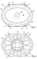
- Figure 2 is a plan view of a loudspeaker protector affixed to a loudspeaker, according to the invention;
- Figure 3 is a plan view of the loudspeaker of Figure 2, with the loudspeaker protector removed, showing a loudspeaker cone supported by a metallic loudspeaker frame;
- Figure 4 is a plan view of the loudspeaker frame of Figure 4;
- Figure 5 is a cross-sectional view through the loudspeaker and loudspeaker protector, taken through line V-V of Figure 2; and
- Figures 6, 7 and 8 are views of the internal surfaces of a car door, before, during and after installation of a loudspeaker with the loudspeaker protector of Figure 2.
-
- Figure 1 shows a prior art loudspeaker protector 1, formed in a rigid moulded plastic material with a continuous
oval rim 2 inside of which are a large number ofperforations 4. Theperforations 4 are circular and closely packed so that these form a grille through which sound emitted by a loudspeaker may pass. - With reference now also to Figures 3 to 6 the loudspeaker protector 1 in use is permanently affixed to a
conventional loudspeaker 30 by applying glue (not shown) between therim 2 of the loudspeaker protector 1 and a similarly shapedrim 39 of a pressedsteel loudspeaker frame 40. Most of this glue is applied between matchingflanges loudspeaker frame 40, in areas surrounding four matchingholes rim 2 of the loudspeaker protector 1 andrim 39 of theloudspeaker frame 40. Theholes bolt 38 can be passed through each of the aligned pairs ofholes bores 47 in anenclosure 75, such as a recess in a metallicmotor vehicle door 80, to mount and secure theloudspeaker 30 to theenclosure 75. - The loudspeaker protector 1 serves another purpose in this automotive application, by providing electrical insulation between the
loudspeaker frame 30 and the four metal screws orbolts 38 used to secure theloudspeaker 30 to themetallic enclosure 75. This insulation is ensured by acylindrical sleeve 16 that inserts fully into the loudspeakerframe clearance holes 8 when the loudspeaker protector 1 is affixed to theloudspeaker 30. This electrical insulation is important because it prevents electrical current from flowing from themetallic loudspeaker frame 40 to the metallic chassis of the vehicle through the connecting screw orbolt 38, in the event that an electrical fault develops within theloudspeaker 30. Because of this need for electrical insulation, the loudspeaker protector 1 must be permanently affixed to theloudspeaker frame 40. This does provide the benefit that physical protection is always provided to delicate components of the loudspeaker, in particular aloudspeaker cone 20, ainner loudspeaker cone 22, and aflexible surround 24 around thecone 20. Usually, theloudspeaker cone 20 andinner loudspeaker cone 24 will be made from paper. However, thegrille 4 does impair somewhat the sound quality of thespeaker 30. - In order to minimise this impairment, the loudspeaker protector 1 is moulded from a relatively expensive plastic material sold under the trade mark Noryl, which is a PPE-PS blend. This has high strength, and is suitable for use with adhesives that can affix this permanently to the
metal loudspeaker frame 40. - Even in high volume production, the cost of the prior art loudspeaker protector 1 is about US$ 0.20 to US$ 0.25. This is a significant additional cost to the manufacturing cost of the
loudspeaker 30. - Figure 2 shows a
loudspeaker protector 25 according to the invention, when affixed to theloudspeaker 30 of Figure 3. Theloudspeaker protector 25 comprises a sheet offlexible material 26, which is preferably 250 µm thick film, for example polyester film (PET) or polyether sulphone (PES), which has been cut and moulded into shape. Theloudspeaker protector 25 has anedge 28 that generally conforms to theperipheral outline 29 of theloudspeaker 30, with the exception of atab 32 that extends outwards from arim area 34 of theprotector 25. - The
loudspeaker protector 25 has four mounting points in the form ofclearance holes 36 in therim 34. When theprotector 25 is affixed to theloudspeaker 30, these fourclearance holes 36 align with the fourholes 8 in themetallic frame 40 of theloudspeaker 30. - Figure 5 shows a cross-sectional view through the
loudspeaker protector 25 when affixed to theloudspeaker 30 by means of an adhesive 37 in the vicinity of the loudspeakerprotector clearance holes 36. Also shown, is the metallic screw orbolt 38 passing through thehole 36 in theprotector 25 and the matchingclearance hole 8 in the loudspeakermetallic frame 40. - The
loudspeaker protector 25 has acylindrical sleeve 42 that extends through theframe clearance hole 8 so that themetallic screw 38 cannot contact themetallic frame 40. A compressiblehemispheric button 44, for example made from a foam-like material or an elastomeric material, is also provided on anundersurface 54 of theflange 14 of theloudspeaker frame 40 to provide vibration isolation and electrical insulation between theframe 40 and ametallic support surface 46 to which theloudspeaker 30 is secured by the four screws orbolts 38. - As indicated by Figures 5 and 6, the
loudspeaker 30 withloudspeaker protector 25 is first assembled to the supportingsurface 46 with theloudspeaker protector 25 still protecting theloudspeaker cone 20. Theloudspeaker protector 25 hassemicircular perforations 50 that extend around each of themounting points 36 of theprotector 25, terminating at aperipheral edge 28 of the protector. The perforations therefore separate acentral portion 52 of theprotector 25 from foursmall portions 56 ofsheet material 26 that extend around each of the fourclearance holes 36. - The
perforations 50 form a line of weakness in theloudspeaker protector 25 so that a person may grip the projectingtab 32 and lift theprotector 25 away from theloudspeaker 30 to cause theprotector 25 to tear along each of the fourperforations 50, and thereby remove the loudspeaker protectorcentral portion 52 from theloudspeaker 30. Theloudspeaker protector 25 is substantially removed from theloudspeaker 30, except for the foursmall portions 56 that remain adhered by theadhesive 37 and secured by thebolt 38 to theperipheral flanges 14 in theloudspeaker frame 40. The cylindricalinsulating sleeves 42 therefore remain in place between themetallic screw 38 andloudspeaker frame 40. - As can be seen from Figure 2, the pull-tab extends from a rim or
peripheral region 34 of the sheet material forming theloudspeaker protector 52, but in such a way that this pull-tab 32 does not extend beyondrectangular bounds 60 defined by the long andshort axes oval loudspeaker cone 20. This arrangement facilitates packaging of the assembledloudspeaker 30 andprotector 25, e.g. inside a matching rectangular cardboard shipping box (not shown). The pull-tab 32 therefore extends in a direction that lies between themajor axis 62 andminor axis 64 of theoval loudspeaker 30. - The
central area 52 of theloudspeaker protector 25 is provided with a series ofparallel corrugations 66 which have a rectangular channel cross-section as shown in Figure 5. Thecorrugations 66 extend in a direction transverse to apull direction 68 of the pull-tab 32. Thecorrugations 66 therefore permit thecentral area 52 to curl and roll in thepull direction 68 as the pull-tab 32 is used to remove thecentral area 52 of theloudspeaker protector 25 from theloudspeaker 30. Thecorrugations 66 therefore provide stiffening in a direction normal to the plane of Figure 2, while still permitting easy removal of thecentral area 52 of theprotector 25 after theloudspeaker 30 has been installed in itsenclosure 75. - In order to help ensure that the
central area 52 is removed after installation of theloudspeaker 30, it is preferable if the loudspeakercentral area 52 has a colour noticeably different from that of theloudspeaker cone 20. Usually,loudspeaker cones 20 are black, and so at least a portion of thecentral area 52 should be coloured with a colour other than black. Similarly, because theareas 56 of theloudspeaker protector 25 are left in place after removal of thecentral area 52, it is preferable if theseperipheral regions 56 of theloudspeaker protector 25 are coloured black. - In order to provide the maximum protection, the
central area 52 of theloudspeaker protector 25 is domed by astep 70 that rises from theperipheral rim 34 of theprotector 25. This provides aclearance gap 72 between therubber isolating ring 24 connecting theloudspeaker cone 20 to theloudspeaker frame 40. - The
loudspeaker protector 25 according to the invention is relatively cheap to manufacture in large volumes. Because theprotector 25 is temporary, it does not need to be designed to let sound from the loudspeaker pass through the protector with minimum disturbance. There is also no need to design theprotector 25 so that this does not rattle or vibrate when the loudspeaker is operational. The material of theloudspeaker protector 25 may also be recyclable, thereby providing additional cost savings and reduced environmental impact. A loudspeaker protector according to the invention therefore provides an economical solution to the problem of how to provide protection to the fragile parts of a loudspeaker between the manufacture of the loudspeaker and installation in an enclosure.
Claims (15)
- A loudspeaker protector (25), comprising: a sheet of flexible material (26), the sheet being bounded by an edge (28); one or more mounting points (36) on the sheet (26), each mounting point (26) being adapted to receive a fixing member (38) through the sheet (26) and being positioned in a peripheral region (56) of the sheet (26); characterised in that the loudspeaker protector comprises one or more lines of weakness (50) in the sheet, the sheet (26) being thereby adapted to tear or break preferentially along the lines of weakness (50); in which the lines of weakness (50) separate the peripheral region (56) at each mounting point (26) from a central area (52) of the sheet (26), so that the central area (52) of the sheet (26) may be torn from the peripheral region(s) (56) after the or each mounting point (36) has been held down by said fixing member(s) (38).
- A loudspeaker protector (25) as claimed in Claim 1, in which the or each mounting point is a hole (36) through the sheet (26), the sheet including a sleeve (42) that extends transversely away from the sheet (26) around said hole (36).
- A loudspeaker protector (25) as claimed in Claim 1 or Claim 2, in which the sheet (26) includes a pull-tab (32) that extends from a peripheral region (56) of the sheet (26).
- A loudspeaker protector (25) as claimed in Claim 3, in which the sheet (26) is elongate with a major axis (62) extending along the length of the sheet (26), and a minor axis (64) extending transverse to the major axis (62) along the width of the sheet (26), the pull-tab (32) extending between the major axis (62) and the minor axis (64).
- A loudspeaker protector (25) as claimed in Claim 4, in which the major axis (62) and minor axis (64) define the orientation of a notional rectangle with length and width equal to that of the elongate sheet (26), the tab (32) not extending beyond the bounds of the notional rectangle.
- A loudspeaker protector (25) as claimed in any preceding claim, in which at least a portion of the sheet (26) is coloured with a colour other than black.
- A loudspeaker protector (25) as claimed in any preceding claim, in which the peripheral region(s) (56) of the sheet (26) beyond the lines of weakness (50) are coloured black.
- A loudspeaker protector (25) as claimed in any preceding claim, in which the sheet (26) has a domed central area (52).
- A loudspeaker protector (25) as claimed in any preceding claim, in which the central area (52) of the sheet (26) includes corrugations (66).
- A loudspeaker (30), comprising a frame (40), one or more mounting features (8) by which the loudspeaker (30) may be secured to an external object (80), a loudspeaker cone (20), and a loudspeaker protector (25), in which the cone (20) is supported peripherally by the frame (40), the mounting features (8) are provided on the frame (40) beyond the periphery of the cone (20), the loudspeaker protector (25) is affixed to the frame (40) to protect the cone (20) supported within the frame (40), and the loudspeaker protector (25) has one or more mounting points (36) in alignment with the mounting features (8) of the frame (40), wherein the loudspeaker protector (25) is as claimed in any preceding claim.
- A loudspeaker (30) as claimed in Claim 10, in which the frame is a metallic frame (40), the mounting features (8) of the frame (40) being formed in the metal of the frame, and the mounting points (36) of the loudspeaker protector (25) serve to insulate electrically the frame (40) from the fixing member(s) (38).
- A loudspeaker (30) as claimed in Claim 11, in which each of the mounting features is an aperture (8) in the frame (40), and the loudspeaker protector (25) has a sleeve (42) that extends into the aperture (8) to insulate electrically the frame (40) from the fixing member(s) (38).
- A loudspeaker (30) as claimed in Claim 10 or Claim 11, in which the loudspeaker protector (25) is glued (37) to the loudspeaker (30) in the vicinity of the mounting points (36).
- A loudspeaker (30) as claimed in any of Claims 10 to 13, in which the periphery of (28) the loudspeaker protector (25) is essentially the same as that (29) of the loudspeaker frame (40).
- A method of installing a loudspeaker (30) in an enclosure (75) using at least one fixing member (38), the loudspeaker (30) being as claimed in any of Claims 10 to 14, wherein the method comprises the steps of:a) placing the loudspeaker (30) in the enclosure (75);b) using the fixing member(s) (38) to secure the loudspeaker (30) within the enclosure (75); and
characterised in that the method comprises the step of thenc) pulling the loudspeaker protector (25) from the loudspeaker (30) to tear the loudspeaker protector (25) along the lines of weakness (50) in order to remove the central portion of the loudspeaker protector (25) from the loudspeaker (30), while leaving the loudspeaker protector mounting points (36) held to the loudspeaker (30) at the fixing member(s) (38).
Applications Claiming Priority (2)
| Application Number | Priority Date | Filing Date | Title |
|---|---|---|---|
| GB0026265 | 2000-10-27 | ||
| GB0026265A GB2368485A (en) | 2000-10-27 | 2000-10-27 | Loudspeaker cone protector |
Publications (1)
| Publication Number | Publication Date |
|---|---|
| EP1202601A2 true EP1202601A2 (en) | 2002-05-02 |
Family
ID=9902042
Family Applications (1)
| Application Number | Title | Priority Date | Filing Date |
|---|---|---|---|
| EP01308886A Withdrawn EP1202601A2 (en) | 2000-10-27 | 2001-10-19 | Loudspeaker cone protector |
Country Status (3)
| Country | Link |
|---|---|
| US (1) | US6651772B1 (en) |
| EP (1) | EP1202601A2 (en) |
| GB (1) | GB2368485A (en) |
Families Citing this family (5)
| Publication number | Priority date | Publication date | Assignee | Title |
|---|---|---|---|---|
| JP2006229517A (en) * | 2005-02-17 | 2006-08-31 | Pioneer Electronic Corp | Frame for speaker device, and speaker device |
| JP4594127B2 (en) * | 2005-02-17 | 2010-12-08 | パイオニア株式会社 | Frame for speaker device and speaker device |
| CN101304622A (en) * | 2007-05-09 | 2008-11-12 | 富准精密工业(深圳)有限公司 | Audio film structure of electroacoustic apparatus and preparation method thereof |
| WO2017079323A1 (en) * | 2015-11-03 | 2017-05-11 | Thomas & Darden, Inc. | Speaker enclosure having enhanced acoustic properties |
| JP7484546B2 (en) * | 2020-08-07 | 2024-05-16 | ヤマハ株式会社 | headphone |
Family Cites Families (7)
| Publication number | Priority date | Publication date | Assignee | Title |
|---|---|---|---|---|
| US4281224A (en) * | 1980-04-21 | 1981-07-28 | Sparkomatic Corporation | Grille covered speaker assembly construction for compact automobiles and the like |
| JPH02260799A (en) * | 1989-03-30 | 1990-10-23 | Pioneer Electron Corp | Speaker and its manufacture |
| US4919227A (en) * | 1989-06-08 | 1990-04-24 | Oits Elevator Company | Tamper resistant speaker grille for intercom module |
| US4974698A (en) * | 1989-10-11 | 1990-12-04 | Oakwood Metal Fabricating Company | Speaker cover grille installation |
| JPH07107582A (en) * | 1993-09-30 | 1995-04-21 | Tohoku Pioneer Kk | On-vehicle speaker |
| GB2305064A (en) * | 1995-09-09 | 1997-03-26 | Rover Group | Loudspeaker grille mounting arrangement |
| USD473213S1 (en) * | 2002-01-02 | 2003-04-15 | Audiobahn, Inc. | Speaker grill |
-
2000
- 2000-10-27 GB GB0026265A patent/GB2368485A/en not_active Withdrawn
-
2001
- 2001-10-19 EP EP01308886A patent/EP1202601A2/en not_active Withdrawn
- 2001-10-25 US US10/056,677 patent/US6651772B1/en not_active Expired - Fee Related
Also Published As
| Publication number | Publication date |
|---|---|
| GB0026265D0 (en) | 2000-12-13 |
| GB2368485A (en) | 2002-05-01 |
| US6651772B1 (en) | 2003-11-25 |
Similar Documents
| Publication | Publication Date | Title |
|---|---|---|
| EP1759935A1 (en) | Airbag device and covering member thereof | |
| US6651772B1 (en) | Loudspeaker cone protector | |
| US20080013780A1 (en) | Speaker device | |
| JP2001356692A (en) | Peeling fracture structure of display label | |
| JP3797561B2 (en) | Speaker device | |
| US20060222801A1 (en) | Protective film | |
| JP2007181015A (en) | Speaker bracket and speaker device | |
| CN211471277U (en) | Electronic product protective film | |
| KR101062541B1 (en) | Airbag Module Assembly Structure | |
| JP2005277870A (en) | Speaker device and method of manufacturing speaker device | |
| CN115950458A (en) | Detection device and steering wheel | |
| JP3028941U (en) | Airbag module with built-in horn switch | |
| JP2898924B2 (en) | Instrument panel with integrated airbag door insert and airbag door | |
| CN222665753U (en) | A protective film for a vehicle-mounted touch screen and a material strip thereof | |
| JP3362550B2 (en) | Airbag device pad | |
| US11477578B1 (en) | Speaker basket with splash shield | |
| JPH0113496Y2 (en) | ||
| JP4177000B2 (en) | Bushing protection cover and bushing protection method for power transformer | |
| JPH11321516A (en) | Steering wheel | |
| JP3455876B2 (en) | Speaker | |
| JP5029437B2 (en) | Vehicle side collision detection device and vehicle occupant protection system using the same | |
| JPH069320U (en) | Wire protector | |
| JPH08284784A (en) | Starter | |
| JP3999064B2 (en) | Wire harness mounting structure | |
| JP4287257B2 (en) | Protective cover device |
Legal Events
| Date | Code | Title | Description |
|---|---|---|---|
| PUAI | Public reference made under article 153(3) epc to a published international application that has entered the european phase |
Free format text: ORIGINAL CODE: 0009012 |
|
| AK | Designated contracting states |
Kind code of ref document: A2 Designated state(s): AT BE CH CY DE DK ES FI FR GB GR IE IT LI LU MC NL PT SE TR |
|
| AX | Request for extension of the european patent |
Free format text: AL;LT;LV;MK;RO;SI |
|
| STAA | Information on the status of an ep patent application or granted ep patent |
Free format text: STATUS: THE APPLICATION IS DEEMED TO BE WITHDRAWN |
|
| 18D | Application deemed to be withdrawn |
Effective date: 20031101 |