EP1202315A1 - Actionneur à billes - Google Patents
Actionneur à billes Download PDFInfo
- Publication number
- EP1202315A1 EP1202315A1 EP01410119A EP01410119A EP1202315A1 EP 1202315 A1 EP1202315 A1 EP 1202315A1 EP 01410119 A EP01410119 A EP 01410119A EP 01410119 A EP01410119 A EP 01410119A EP 1202315 A1 EP1202315 A1 EP 1202315A1
- Authority
- EP
- European Patent Office
- Prior art keywords
- rod
- striker
- control
- balls
- translation
- Prior art date
- Legal status (The legal status is an assumption and is not a legal conclusion. Google has not performed a legal analysis and makes no representation as to the accuracy of the status listed.)
- Withdrawn
Links
- 238000005096 rolling process Methods 0.000 claims description 12
- 238000009825 accumulation Methods 0.000 claims description 10
- 238000003860 storage Methods 0.000 claims description 6
- 239000003302 ferromagnetic material Substances 0.000 claims description 4
- 238000004804 winding Methods 0.000 claims description 4
- 230000005284 excitation Effects 0.000 claims description 2
- 230000007246 mechanism Effects 0.000 description 10
- 239000000543 intermediate Substances 0.000 description 8
- 230000005291 magnetic effect Effects 0.000 description 6
- 230000004907 flux Effects 0.000 description 3
- 238000012423 maintenance Methods 0.000 description 3
- 238000005381 potential energy Methods 0.000 description 3
- 230000035939 shock Effects 0.000 description 3
- 230000009471 action Effects 0.000 description 2
- 230000008901 benefit Effects 0.000 description 2
- 239000006185 dispersion Substances 0.000 description 2
- 238000006073 displacement reaction Methods 0.000 description 2
- 239000000428 dust Substances 0.000 description 2
- 230000000694 effects Effects 0.000 description 2
- 230000005484 gravity Effects 0.000 description 2
- 238000004519 manufacturing process Methods 0.000 description 2
- 230000009467 reduction Effects 0.000 description 2
- 244000089409 Erythrina poeppigiana Species 0.000 description 1
- 235000009776 Rathbunia alamosensis Nutrition 0.000 description 1
- 241001080024 Telles Species 0.000 description 1
- 238000006243 chemical reaction Methods 0.000 description 1
- 230000006835 compression Effects 0.000 description 1
- 238000007906 compression Methods 0.000 description 1
- 230000005347 demagnetization Effects 0.000 description 1
- 238000010586 diagram Methods 0.000 description 1
- 238000009826 distribution Methods 0.000 description 1
- 230000005294 ferromagnetic effect Effects 0.000 description 1
- 230000003993 interaction Effects 0.000 description 1
- 230000009916 joint effect Effects 0.000 description 1
- 239000000463 material Substances 0.000 description 1
- 238000012986 modification Methods 0.000 description 1
- 230000004048 modification Effects 0.000 description 1
- 230000007935 neutral effect Effects 0.000 description 1
- 230000002040 relaxant effect Effects 0.000 description 1
- 230000004044 response Effects 0.000 description 1
- 230000035945 sensitivity Effects 0.000 description 1
Images


Classifications
-
- H—ELECTRICITY
- H01—ELECTRIC ELEMENTS
- H01H—ELECTRIC SWITCHES; RELAYS; SELECTORS; EMERGENCY PROTECTIVE DEVICES
- H01H71/00—Details of the protective switches or relays covered by groups H01H73/00 - H01H83/00
- H01H71/10—Operating or release mechanisms
- H01H71/50—Manual reset mechanisms which may be also used for manual release
- H01H71/505—Latching devices between operating and release mechanism
-
- H—ELECTRICITY
- H01—ELECTRIC ELEMENTS
- H01H—ELECTRIC SWITCHES; RELAYS; SELECTORS; EMERGENCY PROTECTIVE DEVICES
- H01H71/00—Details of the protective switches or relays covered by groups H01H73/00 - H01H83/00
- H01H71/10—Operating or release mechanisms
- H01H71/50—Manual reset mechanisms which may be also used for manual release
- H01H71/505—Latching devices between operating and release mechanism
- H01H2071/506—Latching devices between operating and release mechanism using balls or rollers in the latching device
-
- H—ELECTRICITY
- H01—ELECTRIC ELEMENTS
- H01H—ELECTRIC SWITCHES; RELAYS; SELECTORS; EMERGENCY PROTECTIVE DEVICES
- H01H71/00—Details of the protective switches or relays covered by groups H01H73/00 - H01H83/00
- H01H71/10—Operating or release mechanisms
- H01H71/12—Automatic release mechanisms with or without manual release
- H01H71/24—Electromagnetic mechanisms
- H01H71/2463—Electromagnetic mechanisms with plunger type armatures
Definitions
- the invention relates to a high and low efficiency ball actuator dimensions, intended in particular for the control of an opening mechanism and closing of an electrical switchgear, in particular when controlling a power circuit breaker.
- Document DE 23 40 450 describes a ball locking device for a switch electric, comprising a locking bolt sliding in translation in a housing and a control sub-assembly consisting of an axial movement control rod arranged perpendicular to the axis of translation of the bolt and provided with a plate support for two balls.
- a first of the two balls takes support on one side on a flat end of the bolt, and on the other on the rod.
- the surface of the flat end of the latch is parallel to the contact surface of the rod, so that the bolt transmits to the rod only purely radial forces. These are taken up by the second ball which is interposed between the rod and the housing.
- the end of the bolt has in in addition in a lower part a chamfer forming a ramp.
- Document DE 1,131,304 describes a device for locking a fastening high voltage electric switch, comprising a locking bolt sliding in a housing and bearing a row of four rollers. In the locked position, the four rollers are aligned in the axis of translation of the bolt, and the furthest roller of the bolt is supported on a wall of the housing.
- a pusher allows you to misalign the intermediate rollers located in second and third position, but these rollers intermediates are returned to the alignment position by return springs. As long as the alignment of the four rollers is maintained, the force exerted by the bolt is transmitted completely from roll to roll to the housing. When we act on the pusher, we do roll the two intermediate rollers to their misaligned position against stress return springs.
- an actuator comprising: a housing defining a geometric axis of translation; a control rod movable in translation by relative to the housing parallel to the geometric axis of translation, between a position of locked control and an unlocked control position, and comprising a rolling surface; a striker movable in translation relative to the housing parallel to the geometric axis translation between an armed position and a position unarmed, and having a range; a means of driving the cooperating striker with the striker in such a way that when the striker is in its armed position, the striker drive means returns the striker to the disarmed position; a set of four locking balls, each locking ball being movable between a locking position and a withdrawing position, each locking ball in locking position being in abutment against said bearing surface of the striker, each ball of lock having a center; a set of four trackballs, each of order having a center; the actuator being such that when the striker is in position armed and the rod in the
- the document DE 1.006.044 describes a locking system comprising a control ball and two locking balls, to allow a reduction of the efforts.
- a locking mechanism of a similar type, with a control ball and two locking balls, is described in the document FR2.417.177. Such mechanisms are limited in power by the low number of drive balls and the low number locking balls. In addition, two locking balls are required for a command ball.
- the invention therefore aims to remedy the drawbacks of the state of the art, so as to propose a high efficiency ball actuator, requiring a very low energy maneuver to release significant mechanical energy.
- the interposition of a control ball between two locking balls allows a distribution of forces such as the forces applied by the control balls to the rod have a component perpendicular to the axis of translation of the rod which is less than the component in a plane perpendicular to the axis of translation of the force rod applied by the striker to the locking balls. In other words, part of forces applied by the striker are not transmitted to the rod.
- each control ball rolls on the running surface.
- the control energy necessary for the displacement of the rod between its position of control locked and its control position unlocked is weak. This allows reduce the power, consumption and size of the drive device the stem.
- the mobile mass constituted by the balls is relatively small and their displacement is of very small amplitude, on the one hand, the unlocking of the striker following the movement of the rod is very fast, which ensures a response time particularly efficient, and that on the other hand, the potential energy stored in the spring is almost completely transmitted to the striker, which ensures a very good mechanism performance.
- the movement of the rod is perpendicular to the first and second planes, so that the balls work by rolling on the rod, not by sliding, where from a wear minimal.
- the striker drive means comprises a spring accumulating cooperating with the housing and the striker, so that when the striker is in its armed position, the storage spring is in a state loaded and returns the striker to the disarmed position.
- the energy needed to training the rod is very weak for a significant potential energy stored in the accumulation spring.
- the actuator obtained constitutes a functional unit requiring no significant adjustments during its implementation.
- the storage spring is a helical spring coaxial with the axis geometric.
- the rod is arranged along the geometric axis of translation, the scope of the striker forms a surface of revolution around the geometric axis of translation, the centers of the locking balls form n vertices of an n-sided polygon centered on the geometric axis of translation and the centers of the control balls form n vertices of a polygon with n sides centered on the geometric axis of translation. So the marbles control are automatically centered by the joint action of the locking balls, which makes the device relatively insensitive to the effects of dimensional dispersions and to wear.
- the device further comprises a means for returning the rod towards the locked control position and means for driving the rod to the position of control unlocked. Due to the multiplication of the locking forces obtained thanks to the relative arrangement of the control balls and the locking balls, the force that the rod return means must exercise is relatively weak, so that the means rod drive has only a small energy to provide to counteract the action of the means rod return and drive the rod to the unlocked position.
- a mobile assembly made of ferromagnetic material slides in translation integrally with the rod.
- the means of rod training has an electromagnetic excitation winding to drive the moving part.
- the mobile assembly is housed in a cavity of the housing.
- the winding is supported by the housing.
- the dimension chains are then reduced. Reliability of the device is improved.
- the assembly obtained is particularly compact.
- the mobile assembly consists of a part of the rod. Number of parts is reduced.
- the rod return means comprises a permanent magnet attracting the moving crew.
- the permanent magnet alone ensures the maintenance of the rod in the locked position and possibly all or part of the rod reset. This considerably reduces the power consumption of the actuator ordered.
- the rod return means comprises a spring.
- the rod has an axial stop on which the control balls when the striker is in the armed position and the rod in the control locked, the first and second geometric planes being distinct, the second geometric plane being located between the first geometric plane and the axial stop.
- the rod passing from the locked control position to the position unlocked, moves in one direction, the second plane being offset from the first geometric plane in said direction of ordered.
- the result of the forces exerted by the control balls on the rod then has an axial component tending to drive the rod towards its control position unlocked.
- the trigger movement is then very fast, and the power necessary to maneuver the rod to the unlocked position is very small.
- a movable auxiliary pusher drives the rod from the position of control locked in the unlocked control position when switching from a first and a second position.
- the push-button allows the mechanism to be operated manually to check the operation of the actuator. It also ensures the triggering by mechanism external to the device and intended to operate in parallel with the electromagnetic control actuator.
- control balls, the locking balls and at least one part of the rod are housed in a cavity bounded by walls of the housing and by the striker, said walls forming a guide surface cooperating with the striker so as to ensure dust tightness when the striker moves between the armed position and the disarmed position.
- the reliability of the mechanism is thus ensured with great economy of means.
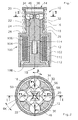
- a ball actuator 10 according to a first mode of embodiment of the invention comprises a housing 12 supporting a striker 14 with spring accumulation 16, a control rod 18 movable in translation parallel to an axis geometric 19, locking balls 20 and control balls 22.
- the housing 12 forms a bore 24 of internal axial guide for the control rod 18, a cylindrical surface 26 of external guide for the striker 14, a supporting shoulder 28 for one end of the accumulation spring 16 and a cage 30 visible in FIG. 2, for receiving the locking balls 20 and the control balls 22.
- the striker 14 has a cylindrical tubular part 32 sliding on the outer guide surface 26 of the housing, and is extended by a recess 34 of slightly larger internal diameter, closed by a cap 36 serving support for a second end of the accumulation spring 16.
- the striker 14 and the outer guide surface 26 of the housing are machined so as to provide a seal at dust.
- a chamfer 40 visible in particular in Figure 3, connects the part tubular guide 32 for recess 34.
- the rod 18 has a guide surface 44 sliding on the walls 24 of the axial internal guide bore of the housing, and a surface cylindrical bearing 46.
- the accumulation spring 16 is a compression spring, which accumulates potential energy when compressed and releases kinetic energy when relaxing.
- the cage 30 has surfaces radial guide 50 ensuring radial guidance of the locking balls 20 and axial guide surfaces 52, 54 ensuring the axial maintenance of the locking balls 20.
- An electromagnetic relay 100 with electromagnet is associated with the actuator to drive the control rod 18.
- the relay is housed in a recess 102 of the housing and comprises a shunt 104 intended to develop the magnetic field, a magnetizing coil 106, a plug 108 to close the magnetic flux and a return spring 110, all positioned and guided by an insulating frame 112.
- the rod 18 is made of material ferromagnetic and thus constitutes a plunger core biased by the return spring 110 in the direction of a widening of the air gap 114 between the rod 18 and the shunt 104.
- the centers of locking balls 20 form the vertices of a first polygon 56, in this case a square, located in a plane geometric perpendicular to the axis of translation 19 of the rod, in this case the plane of section II-II of FIG. 2.
- the control balls 22 are in contact with the surface of rod bearing, and are inserted between the locking balls 20.
- the centers of the control balls 22 constitute the vertices of a second polygon 58, in the occurrence of a square, also located in the geometric section plane II-II of FIG.
- each locking ball 20 is supported on two control balls 22 and that each control ball 22 serves as a support for two locking balls 20.
- the balls control are in abutment against the axial stop 54.
- the locking balls 20 are in support against the chamfer 40.
- the accumulation spring 16 is compressed.
- the striker 14 is therefore locked in position by the locking balls 20, which are themselves blocked by the control balls 22 held in position by the rod under the thrust of the spring reminder which tends to spread the rod of the shunt.
- the rod 18 is in a position called control locked.
- the coil 106 is fed.
- the plunger core constituted by the rod 18 is drawn in the direction of the arrow 116 in FIG. 4 and is pressed against the shunt 104 against the return force of the spring 110.
- the control balls 22 roll on the rolling surface 46 as shown in FIG. 4 and leave the geometrical plane of section of Figure 2.
- the locking balls under the bevel thrust 40, eject the control balls 22 which escape in the direction axial according to the arrows shown in FIG. 5.
- the locking balls 20 disappear radially towards the rod 18 in the space freed up as shown in FIG. 6, and release the striker 14.
- the striker 14 is driven by the accumulation spring 16 upwards until reaching a disarmed position shown in Figure 5.
- the rod 18 is found in a so-called unlocked control position.
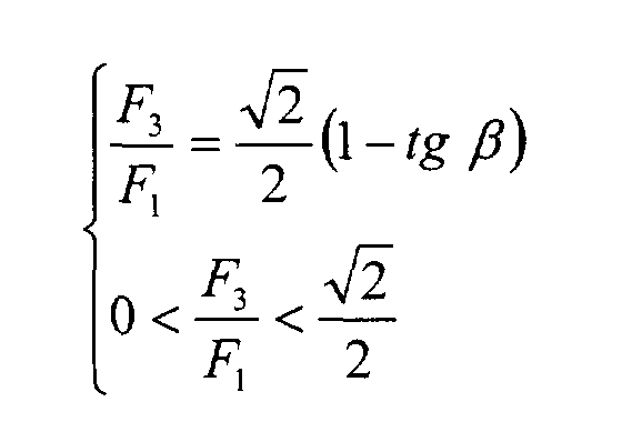
- n is an integer greater than 2, which represents the number of locking balls, moreover equal to the number of control balls.
- the module F 3 of the force exerted by the control balls on the rod in the armed position conditions the energy necessary for the operation of the rod.
- the angle ⁇ can be varied in the interval, and therefore the value of F 3 for a given locking force F 1 . It is therefore possible to obtain a wide range of actuators using more or less powerful springs, without having to vary the operating energy.
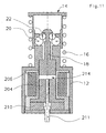
- the actuator according to the second embodiment of the invention shown in the Figures 8 to 11 is similar to that of the first embodiment, so that the same reference signs have been taken to designate identical elements or Similar.
- the actuator according to the second embodiment differs from the previous one essentially by the fact that in the armed position, the centers of the locking balls 20 are in a first geometric plane 60 perpendicular to the axis of translation 19 of the rod, and the centers of the control balls are in a second plane 62, parallel to the foreground 60, and offset with respect to the latter. This provision has the effect add an axial component to the force transmitted by the locking balls to the balls in the armed position.
- the control balls 22 In the armed position, the control balls 22 relate to an axial stop 64 formed by a head 48 of the rod and transmit to it the axial forces. he it is therefore necessary to apply an axial holding force to the rod 18, so that keep the actuator in the armed position. When the maintenance effort is interrupted, the control balls 22 push back the rod 18 and move upwards, releasing the balls lock 20.
- An electromagnetic relay 200 is associated with the actuator to drive the rod 18.
- the relay is housed in a recess 102 of the housing and includes a shunt 204 intended for develop the magnetic field, a demagnetization coil 206, a plug 208 for closing the magnetic flux, a permanent magnet 210 placed opposite to the end of the rod 18 and a mechanical pusher 211, the whole guided and maintained by a frame 212.
- the rod 18 is made of ferromagnetic material and constitutes a plunger core of the relay 200.
- the actuator according to the second embodiment of the invention operates from the next way.
- the permanent magnet 210 recalls the rod towards its locked control position, with a force greater than the resultant axial forces exerted by the control balls 22 on the rod 18, so that the permanent magnet 210 maintains the rod 18 in the control position locked.
- the coil 206 When the coil 206 is energized, it produces a magnetic flux canceling out that of the permanent magnet 210, so that the rod 18, urged by the balls of command 22, comes off the shunt 204 and creates an air gap 214.
- the command balls roll on the rolling surface 46 as shown in figure 10, then are ejected as shown in Figure 11.
- the device is reset by bringing back a any means the striker to the armed position of figure 8.
- the push-button 211 is an optional element which allows triggering mechanical of the device. In the armed position of figure 8, it rests by one end against the end of the rod 18. If the push button 211 is pressed, it drives the rod 18.
- control balls 22 are stressed radially and axially on the one hand by the two neighboring locking balls 20, and on the other hand by the rod 18, at the level of the head 48 and of the rolling surface 46.
- the centering of the control balls 22 and making up for the differences in dimensions are done naturally.
- the actuator can be reset by an interaction between the rod and the striker: in a first step, the striker is returned to the armed position and pushes back the head of the rod, freeing up the space necessary for housing the balls, then in a second stage, the striker continues its race beyond the armed position to tackle the rod against the permanent magnet. This limits the power of the magnet permanent.
- the invention is applicable with any number n of locking balls, n being a whole number greater than or equal to three.
- n being a whole number greater than or equal to three.
- the centers of locking balls form an polygon with n sides and the centers of trackballs also form an n-sided polygon, inscribed at inside the previous one, and offset by ⁇ / n compared to the previous one.
- each control ball is located between the rod on the one hand, and a plane parallel to the translation axis 19 and passing through the centers of the two locking balls with which it is in contact on the other hand, which amounts to saying that a certain so that each locking ball is between the two locking balls with which it is in contact and the rod.
- the storage spring can be replaced by any other type of drive means ensuring the striker drive from the armed position to the disarmed position, as well as constant return to the disarmed position, as long as the striker is in position army.
- a drive means consisting of a mass acting by gravity on the end of the striker, if the latter is placed towards the bottom, in the opposite direction to that illustrated by the figures.
- the electromagnetic relay can be of any type: with or without permanent magnet, polarized or not, etc ...
- the actuator can be associated with any other control device than an electromagnet.
- the rod is not necessarily made of ferromagnetic material, it can be attached to a magnetic core.
- first and second embodiments can be reversed. So it is possible to adapt a permanent magnet relay to an actuator having, in the control position locked, locking ball centers and coplanar control balls. Conversely, it is possible to adapt a spring-loaded relay to an actuator having two separate shots 60, 62.
- the electromagnetic relay can be housed in a box independent of the box the actuator. Shunt and plug can be in one piece.
- the running surface may have a non-circular radial section, for example a polygonal section with a flat facet by control ball.
- the radial section of the rolling surface may not be constant.
- the running surface can be frustoconical, so that the force applied by the control balls to the rod has an axial component.
- the rolling surface can be a surface of revolution around the axis of translation of the rod having any curvature, thus allowing modulation of the axial component of the resultant of the forces applied by the control balls to the rod during movement of the rod.
- the direction of movement of the striker when the accumulation spring is released can be opposite to the direction of movement of the rod from its locked control position to its unlocked control position.
- the rod can protrude through the striker.
- the plane containing the centers of the balls of control is located below the plane containing the centers of the locking balls, so that the control balls exert on an intermediate stop of the rod a force having an axial component tending to push the rod against a limit stop.
- Such an actuator has a stable armed position.
- the rod To release the storage spring, the rod must be driven upward so that the trackballs push back radially outwards the locking balls, which, in contact with a ramp of the shoulder, push the striker axially against the force exerted by the spring accumulation.
- the control balls are ejected as in the previous embodiments and the striker is released.
- This embodiment offers naturally the advantage of greater stability in the armed position, but it requires greater control energy.
- the actuator is not necessarily associated with a drive electromagnetic.
Landscapes
- Lock And Its Accessories (AREA)
- Electromagnets (AREA)
- Breakers (AREA)
Abstract
Description
- un boítier définissant un axe géométrique de translation ;
- une tige de commande mobile en translation par rapport au boítier parallèlement à l'axe géométrique de translation, entre une position de commande verrouillée et une position de commande déverrouillée, et comportant une surface de roulement,
- un percuteur mobile en translation par rapport au boítier parallèlement à l'axe géométrique translation entre une position armée et une position désarmée, et comportant une portée,
- un moyen d'entraínement du percuteur coopérant avec le percuteur de telle manière que lorsque le percuteur est dans sa position armée, le moyen d'entraínement du percuteur rappelle le percuteur vers la position désarmée,
- un ensemble de n billes de verrouillage, n étant un nombre entier supérieur ou égal à trois, chaque bille de verrouillage étant mobile entre une position de verrouillage et une position de retrait, chaque bille de verrouillage en position de verrouillage étant en appui contre ladite portée du percuteur, chaque bille de verrouillage ayant un centre,
- un ensemble de n billes de commande, chaque bille de commande ayant un centre,
- la figure 1 représente une coupe axiale d'un dispositif selon un premier mode de réalisation de l'invention, dans une position armée ;
- la figure 2 représente une section radiale agrandie suivant un plan II-II de la figure 1, du dispositif selon le premier mode de réalisation de l'invention, en position armée ;
- la figure 3 représente un détail agrandi de la figure 1 ;
- la figure 4 représente une coupe axiale du dispositif selon le premier mode de réalisation de l'invention, dans une position intermédiaire fugitive de déclenchement ;
- la figure 5 représente une coupe axiale du dispositif selon le premier mode de réalisation de l'invention, dans une position désarmée ;
- la figure 6 représente une section radiale du dispositif selon le premier mode de réalisation de l'invention, dans une position désarmée ;
- la figure 7 représente une section radiale d'un dispositif illustrant un cas limite théorique ;
- la figure 8 représente une coupe axiale d'un dispositif selon un deuxième mode de réalisation de l'invention, en position armée ;
- la figure 9 représente un détail agrandi de la figure 8 ;
- la figure 10 représente une coupe axiale du dispositif selon le deuxième mode de réalisation de l'invention, dans une position intermédiaire fugitive de déclenchement ;
- la figure 11 représente une coupe axiale du dispositif selon le deuxième mode de réalisation de l'invention, dans une position désarmée.
- un angle α entre un axe passant par les centres de deux billes de verrouillage voisines d'une part, et un axe passant par le centre de l'une des deux billes de verrouillage et le centre d'une bille de commande voisine d'autre part ;
- un angle β entre l'axe passant par les centres de deux billes de verrouillage voisines d'une part, et un axe passant par le centre d'une bille de verrouillage et coupant l'axe de translation de la tige d'autre part.


Claims (17)
- Actionneur (10) comportant :l'actionneur étant tel que lorsque le percuteur (14) est en position armée et la tige (18) en position de commande verrouillée, les centres des billes de verrouillage (20) sont disposés dans un premier plan géométrique (II-II, 60) perpendiculaire à l'axe géométrique de translation (19), les centres des billes de commande (22) sont disposés dans un deuxième plan géométrique (II-II, 62) perpendiculaire à l'axe géométrique de translation (19), caractérisé en ce que l'actionneur est tel que lorsque le percuteur (14) est en position armée et la tige (18) en position de commande verrouillée, chaque bille de commande (22) est en appui contre la surface de roulement (40) de la tige et contre deux billes de verrouillage correspondantes appartenant à l'ensemble des billes de verrouillage (20) et le centre de chaque bille de commande (20) est situé entre la tige (18) et un troisième plan géométrique parallèle à l'axe géométrique de translation (19) et passant par le centre de chacune desdites deux billes de verrouillage correspondantes.un boítier (12) définissant un axe géométrique de translation (19) ;une tige de commande (18) mobile en translation par rapport au boítier (12) parallèlement à l'axe géométrique de translation (19), entre une position de commande verrouillée et une position de commande déverrouillée, et comportant une surface de roulement (46),un percuteur (14) mobile en translation par rapport au boítier parallèlement à l'axe géométrique de translation (19) entre une position armée et une position désarmée, et comportant une portée (40),un moyen d'entraínement (16) du percuteur (14) coopérant avec le percuteur (14) de telle manière que lorsque le percuteur (14) est dans sa position armée, le moyen d'entraínement (16) du percuteur rappelle le percuteur vers la position désarmée,un ensemble de n billes de verrouillage (20), n étant un nombre entier supérieur ou égal à trois, chaque bille de verrouillage (20) étant mobile entre une position de verrouillage et une position de retrait, chaque bille de verrouillage (20) en position de verrouillage étant en appui contre ladite portée (40) du percuteur, chaque bille de verrouillage ayant un centre,un ensemble de n billes de commande (22), chaque bille de commande ayant un centre,
- Actionneur selon la revendication 1, caractérisé en ce que le moyen d'entraínement (16) du percuteur (14) comporte un ressort d'accumulation (16) coopérant avec le boítier (12) et avec le percuteur (14) de telle manière que lorsque le percuteur (14) est dans sa position armée, le ressort d'accumulation (16) se trouve dans un état chargé et rappelle le percuteur (14) vers la position désarmée.
- Actionneur selon la revendication 2, caractérisé en ce que le ressort d'accumulation (16) est un ressort hélicoïdal coaxial avec l'axe géométrique (19).
- Actionneur selon l'une quelconque des revendications précédentes, caractérisé en ce que la tige (18) est disposée le long de l'axe géométrique de translation (19), la portée (40) du percuteur forme une surface de révolution autour de l'axe géométrique de translation (19), les centres des billes de verrouillage forment n sommets d'un polygone (56) à n côtés centré sur l'axe géométrique de translation (19) et les centres des billes de commande forment n sommets d'un polygone (58) à n côtés centré sur l'axe géométrique de translation (19).
- Actionneur selon l'une quelconque des revendications précédentes, caractérisé en ce qu'il comporte en outre :un moyen de rappel de la tige (110, 210) vers la position de commande verrouillée ;un moyen d'entraínement de la tige (106, 206) vers la position de commande déverrouillée.
- Actionneur selon la revendication 5, caractérisé en ce qu'il comporte en outre un équipage mobile en matériau ferromagnétique coulissant en translation solidairement avec la tige, le moyen d'entraínement de la tige (106, 206) comportant un enroulement (106, 206) d'excitation électromagnétique pour entraíner l'équipage mobile.
- Actionneur selon la revendication 6, caractérisé en ce que l'équipage mobile est logé dans une cavité (102) du boítier.
- Actionneur selon l'une quelconque des revendications 6 ou 7, caractérisé en ce que l'équipage mobile est constitué par une partie de la tige (18).
- Actionneur selon l'une quelconque des revendications 6 à 8, caractérisé en ce que l'enroulement (106, 206) est supporté par le boítier.
- Actionneur selon l'une quelconque des revendications 6 à 9, caractérisé en ce que le moyen de rappel de la tige comporte un aimant permanent (210) attirant l'équipage mobile.
- Actionneur selon l'une quelconque des revendications 6 à 10, caractérisé en ce que le moyen de rappel de la tige comporte un ressort de rappel (110).
- Actionneur selon l'une quelconque des revendications précédentes, caractérisé en ce que la tige (18) comporte une butée axiale (64) sur laquelle portent les billes de commande (22) lorsque le percuteur (14) est en position armée et la tige en position de commande verrouillée, les premier (60) et deuxième (62) plans géométriques étant distincts, le deuxième plan géométrique (62) étant situé entre le premier plan géométrique (60) et la butée axiale (64).
- Actionneur selon la revendication 12, caractérisé en ce qu'il est agencé de telle manière que la tige (18), en passant de la position de commande verrouillée à la position de commande déverrouillée, se déplace dans un sens de commande, le deuxième plan géométrique (62) étant décalé par rapport au premier plan géométrique (60) dans ledit sens de commande.
- Actionneur selon l'une quelconque des revendications 1 à 11, caractérisé en ce que les premier et deuxième plans géométriques (II-II) sont confondus.
- Actionneur selon l'une quelconque des précédentes, caractérisé en ce qu'il comporte en outre un poussoir auxiliaire (211) mobile entraínant la tige (18) de la position de commande verrouillée à la position de commande déverrouillée en passant d'une première et une deuxième positions.
- Actionneur selon l'une quelconque des revendications précédentes, caractérisé en ce que les billes de commande (22), les billes de verrouillage (20) et au moins une partie de la tige (18) sont logées dans une cavité délimitée par des parois du boítier (12) et par le percuteur (14), lesdites parois formant une surface de guidage (26) coopérant avec le percuteur de façon à assurer une étanchéité à la poussière lorsque le percuteur se déplace entre la position armée et la position désarmée.
- Actionneur selon l'une quelconque des revendications précédentes, caractérisé en ce qu'il est agencé de telle manière que lorsque la tige (18) quitte la position de commande verrouillée et commence à se déplacer vers la position de commande déverrouillée, chaque bille de commande (22) roule sur la surface de roulement (40).
Applications Claiming Priority (2)
| Application Number | Priority Date | Filing Date | Title |
|---|---|---|---|
| FR0013789 | 2000-10-27 | ||
| FR0013789A FR2816102B1 (fr) | 2000-10-27 | 2000-10-27 | Actionneur a billes |
Publications (1)
| Publication Number | Publication Date |
|---|---|
| EP1202315A1 true EP1202315A1 (fr) | 2002-05-02 |
Family
ID=8855798
Family Applications (1)
| Application Number | Title | Priority Date | Filing Date |
|---|---|---|---|
| EP01410119A Withdrawn EP1202315A1 (fr) | 2000-10-27 | 2001-09-21 | Actionneur à billes |
Country Status (6)
| Country | Link |
|---|---|
| US (1) | US6377146B1 (fr) |
| EP (1) | EP1202315A1 (fr) |
| JP (1) | JP3868792B2 (fr) |
| CN (1) | CN1220998C (fr) |
| EA (1) | EA003290B1 (fr) |
| FR (1) | FR2816102B1 (fr) |
Families Citing this family (16)
| Publication number | Priority date | Publication date | Assignee | Title |
|---|---|---|---|---|
| US20050030227A1 (en) * | 2003-05-22 | 2005-02-10 | Khosro Shamsaifar | Wireless local area network antenna system and method of use therefore |
| JP4596890B2 (ja) * | 2004-11-11 | 2010-12-15 | シナノケンシ株式会社 | アクチュエータ |
| DE102005042883B4 (de) * | 2005-06-02 | 2008-05-08 | Preh Gmbh | Bestätigungsvorrichtung mit Mitteln zum Blockieren von Bewegungen |
| DE102005026415A1 (de) * | 2005-06-03 | 2006-12-07 | Siemens Ag | Elektromagnetische Antriebseinrichtung |
| US20080036560A1 (en) * | 2006-08-08 | 2008-02-14 | General Electric Company | Electromagnet Apparatus |
| US7557681B2 (en) * | 2007-04-09 | 2009-07-07 | Eaton Corporation | Electrical switching apparatus accessory sub-assembly employing reversible coil frame, and accessory and electrical switching apparatus employing the same |
| US7598830B2 (en) * | 2007-04-09 | 2009-10-06 | Eaton Corporation | Electromagnetic coil apparatus employing a magnetic flux enhancer, and accessory and electrical switching apparatus employing the same |
| DE102008021768B4 (de) | 2007-04-30 | 2023-11-16 | Abb Ag | Elektromagnetischer Auslöser, Verfahren zur Herstellung eines elektromagnetischen Auslösers und Leitungsschutzschalter mit einem elektromagnetischen Auslöser |
| EP2605254B8 (fr) * | 2011-12-12 | 2017-10-04 | Tyco Electronics Belgium EC BVBA | Actionneur électromagnétique |
| CN107527706B (zh) * | 2017-08-10 | 2019-07-05 | 北京特种机械研究所 | 一种大行程、大吸力、自锁力可调、双向比例电磁铁 |
| CN107507712B (zh) * | 2017-08-14 | 2019-09-27 | 江西亚欣澜宇科技有限公司 | 一种闭合稳固的电磁开关 |
| JP6907086B2 (ja) * | 2017-09-28 | 2021-07-21 | 三菱重工コンプレッサ株式会社 | 塞止弁及び蒸気タービン |
| CN109036763A (zh) * | 2018-07-31 | 2018-12-18 | 苏州耀德科电磁技术有限公司 | 一种线性直动电磁铁 |
| US20210110966A1 (en) * | 2019-10-09 | 2021-04-15 | Power Integrations, Inc. | Magnet with multiple discs |
| DE102020201932B3 (de) * | 2020-02-17 | 2020-11-19 | Siemens Aktiengesellschaft | Verklinkungsmechanismus |
| CN113898689A (zh) * | 2021-11-11 | 2022-01-07 | 鞍山电磁阀有限责任公司 | 驱动齿条锁紧装置 |
Citations (5)
| Publication number | Priority date | Publication date | Assignee | Title |
|---|---|---|---|---|
| FR1060856A (fr) * | 1951-04-13 | 1954-04-07 | Bendix Aviat Corp | Perfectionnements aux mécanismes de commande |
| DE1006044B (de) * | 1946-01-18 | 1957-04-11 | Ugo Sabatini | Verriegelungsvorrichtung fuer mechanische Schaltwerke mit hohem Kraftuebersetzungsverhaeltnis, beispielsweise fuer elektrische Schalter |
| DE1131304B (de) * | 1954-03-31 | 1962-06-14 | Siemens Ag | Verriegelungseinrichtung, insbesondere loesbare Verklinkung fuer Hochspannungsschalter u. dgl. |
| DE2340450A1 (de) * | 1973-08-09 | 1975-03-13 | Siemens Ag | Vorrichtung zum loesbaren verriegeln eines elektrischen schalters |
| FR2417177A1 (fr) * | 1978-02-10 | 1979-09-07 | Legrand Sa | Mecanisme d'accrochage et disjoncteur comportant un tel mecanisme |
Family Cites Families (8)
| Publication number | Priority date | Publication date | Assignee | Title |
|---|---|---|---|---|
| US3665813A (en) * | 1970-02-24 | 1972-05-30 | Gen Gas Light Co | Snap operator for pressure fluid valve |
| SU773761A1 (ru) * | 1978-12-18 | 1980-10-23 | Предприятие П/Я А-7794 | Запирающий механизм выключателей |
| US4309022A (en) * | 1980-04-14 | 1982-01-05 | Consolidated Controls Corporation | Poppet valve actuator apparatus |
| SU913469A1 (ru) * | 1980-07-30 | 1982-03-15 | Vni Pk I T I Vzryvozaschi | Кнопочный пост управления 1 |
| EP0294481A4 (fr) * | 1986-12-26 | 1989-04-27 | Mitsubishi Mining & Cement Co | Actuateur electromagnetique. |
| IL91041A0 (en) * | 1988-07-28 | 1990-02-09 | H U Dev Corp | Solenoid actuator |
| US5022690A (en) * | 1989-09-18 | 1991-06-11 | Adams & Coltrin, Inc. | Quick release latch mechanism |
| JP3331400B2 (ja) * | 1993-01-22 | 2002-10-07 | 三信工業株式会社 | 舶用推進機の前後進切替え制御装置 |
-
2000
- 2000-10-27 FR FR0013789A patent/FR2816102B1/fr not_active Expired - Fee Related
-
2001
- 2001-09-21 EP EP01410119A patent/EP1202315A1/fr not_active Withdrawn
- 2001-10-02 US US09/967,974 patent/US6377146B1/en not_active Expired - Lifetime
- 2001-10-15 CN CN01135719.3A patent/CN1220998C/zh not_active Expired - Fee Related
- 2001-10-26 EA EA200101011A patent/EA003290B1/ru not_active IP Right Cessation
- 2001-10-29 JP JP2001331339A patent/JP3868792B2/ja not_active Expired - Fee Related
Patent Citations (5)
| Publication number | Priority date | Publication date | Assignee | Title |
|---|---|---|---|---|
| DE1006044B (de) * | 1946-01-18 | 1957-04-11 | Ugo Sabatini | Verriegelungsvorrichtung fuer mechanische Schaltwerke mit hohem Kraftuebersetzungsverhaeltnis, beispielsweise fuer elektrische Schalter |
| FR1060856A (fr) * | 1951-04-13 | 1954-04-07 | Bendix Aviat Corp | Perfectionnements aux mécanismes de commande |
| DE1131304B (de) * | 1954-03-31 | 1962-06-14 | Siemens Ag | Verriegelungseinrichtung, insbesondere loesbare Verklinkung fuer Hochspannungsschalter u. dgl. |
| DE2340450A1 (de) * | 1973-08-09 | 1975-03-13 | Siemens Ag | Vorrichtung zum loesbaren verriegeln eines elektrischen schalters |
| FR2417177A1 (fr) * | 1978-02-10 | 1979-09-07 | Legrand Sa | Mecanisme d'accrochage et disjoncteur comportant un tel mecanisme |
Also Published As
| Publication number | Publication date |
|---|---|
| EA200101011A1 (ru) | 2002-06-27 |
| JP2002217025A (ja) | 2002-08-02 |
| EA003290B1 (ru) | 2003-04-24 |
| US6377146B1 (en) | 2002-04-23 |
| CN1351360A (zh) | 2002-05-29 |
| FR2816102A1 (fr) | 2002-05-03 |
| CN1220998C (zh) | 2005-09-28 |
| FR2816102B1 (fr) | 2003-06-06 |
| JP3868792B2 (ja) | 2007-01-17 |
Similar Documents
| Publication | Publication Date | Title |
|---|---|---|
| FR2816102A1 (fr) | Actionneur a billes | |
| EP2559040B1 (fr) | Dispositif de commutation electrique a mecanisme d'actionnement ultra-rapide et interrupteur hybride comprenant un tel dispositif | |
| EP2893106B1 (fr) | Dispositif de verrouillage motorisé résistant aux chocs | |
| EP2513933A1 (fr) | Actionneur electromagnetique a accrochage magnetique et dispositif de coupure comportant un tel actionneur | |
| EP3327518B1 (fr) | Pièce d'horlogerie comprenant un dispositif de commutation d'un mécanisme horloger | |
| EP3018268A1 (fr) | Mécanisme débrayable pour serrure motorisée de type cylindre à bouton | |
| EP3477023A1 (fr) | Serrure et clef pour cette serrure | |
| FR2945065A1 (fr) | Serrure electonique | |
| EP3933153A1 (fr) | Dispositif électromécanique d'actionnement pour un ouvrant avec des aimants permanents portés par au moins une roue de l'embrayage | |
| EP2248971B1 (fr) | Serrure électronique | |
| EP0282858B1 (fr) | Dispositif de stockage d'énergie mécanique à force d'accrochage nulle | |
| WO2012042124A1 (fr) | Actionneur electromagnetique a accrochage magnetique et dispositif de coupure comportant un tel actionneur | |
| WO2015162557A2 (fr) | Actionneur electrique | |
| CA1203825A (fr) | Dispositif amovible de verrouillage d'un contacteur dans sa position de travail | |
| EP2589733B1 (fr) | Dispositif de verrouillage électromagnétique à appui linéique | |
| EP1801956A1 (fr) | Dispositif de déplacement linéaire d'un corps entre deux positions prédéterminées | |
| EP0811738A1 (fr) | Dispositif de verrouillage | |
| EP2359380B1 (fr) | Mecanisme d'entrainement de la manette d'un bloc de commande a distance, et bloc le comprenant | |
| EP2148027A1 (fr) | Dispositif de verrouillage électromecanique | |
| EP3477026B1 (fr) | Clef électronique pour une serrure électronique | |
| EP3477027B1 (fr) | Ensemble comportant une serrure électronique et une clef électronique | |
| EP3799608B1 (fr) | Attaché-case avec mecanisme escamotable | |
| EP1792326B1 (fr) | Actionneur electromagnetique bistable a serrure integree | |
| WO2002065497A1 (fr) | Dispositif de manoeuvre bistable en translation d'un axe mobile | |
| FR2893445A1 (fr) | Relais electromagnetique polarise a accrochage magnetique |
Legal Events
| Date | Code | Title | Description |
|---|---|---|---|
| PUAI | Public reference made under article 153(3) epc to a published international application that has entered the european phase |
Free format text: ORIGINAL CODE: 0009012 |
|
| AK | Designated contracting states |
Kind code of ref document: A1 Designated state(s): AT BE CH CY DE DK ES FI FR GB GR IE IT LI LU MC NL PT SE TR Kind code of ref document: A1 Designated state(s): CH DE ES FR GB IT LI |
|
| AX | Request for extension of the european patent |
Free format text: AL;LT;LV;MK;RO;SI |
|
| RAP1 | Party data changed (applicant data changed or rights of an application transferred) |
Owner name: SCHNEIDER ELECTRIC INDUSTRIES SAS |
|
| 17P | Request for examination filed |
Effective date: 20020830 |
|
| AKX | Designation fees paid |
Free format text: CH DE ES FR GB IT LI |
|
| GRAP | Despatch of communication of intention to grant a patent |
Free format text: ORIGINAL CODE: EPIDOSNIGR1 |
|
| RAP1 | Party data changed (applicant data changed or rights of an application transferred) |
Owner name: SCHNEIDER ELECTRIC INDUSTRIES SAS |
|
| STAA | Information on the status of an ep patent application or granted ep patent |
Free format text: STATUS: THE APPLICATION IS DEEMED TO BE WITHDRAWN |
|
| 18D | Application deemed to be withdrawn |
Effective date: 20090807 |