BACKGROUND OF THE INVENTION
1. Field of the Invention
The present invention relates to a permanent magnet for magnetic bias
used for a magnetic core (hereafter, may be briefly referred to as "core") of an
inductor component, for example, choke coils and transformers. In particular,
the present invention relates to a magnetic core, that is, a low-profile magnetic
core capable of reducing the thickness of the inductor component.
2. Description of the Related Art
Regarding conventional choke coils and transformers used for, for
example, switching power supplies, usually, the alternating current is applied by
superimposing on the direct current. Therefore, the magnetic cores used for
these choke coils and transformers have been required to have an excellent
magnetic permeability characteristic, that is, magnetic saturation with this direct
current superimposition does not occur (this characteristic is referred to as
"direct current superimposition characteristic").
As high-frequency magnetic cores, ferrite magnetic cores and dust
cores have been used. However, the ferrite magnetic core has a high initial
permeability and a small saturation magnetic flux density, and the dust core has
a low initial permeability and a high saturation magnetic flux density. These
characteristics are derived from material properties. Therefore, in many cases,
the dust cores are used in a toroidal shape. On the other hand, regarding the
ferrite magnetic cores, the magnetic saturation with direct current
superimposition has been avoided, for example, by forming a magnetic gap in a
central leg of an E type core.
However, since miniaturization of electronic components is required
accompanying recent request for miniaturization of electronic equipment,
magnetic gaps of the magnetic cores must become small, and requirements for
magnetic cores having a high magnetic permeability for the direct current
superimposition have become intensified.
In general, in order to meet this requirement, magnetic cores having a
high saturation magnetization must be chosen, that is, the magnetic cores not
causing magnetic saturation in high magnetic fields must be chosen. However,
since the saturation magnetization is inevitably determined from a composition
of a material, the saturation magnetization cannot be increased infinitely.
A conventionally suggested method for overcoming the aforementioned
problem was to cancel the direct current magnetic field due to the direct current
superimposition by incorporating a permanent magnet in a magnetic gap
formed in a magnetic path of a magnetic core, that is, to apply the magnetic
bias to the magnetic core.
This magnetic bias method using the permanent magnet was superior
method for improving the direct current superimposition characteristic.
However, since when a metal-sintered magnet was used, an increase of core
loss of the magnetic core was remarkable, and when a ferrite magnet was used,
the superimposition characteristic did not be stabilized, this method could not be
put in practical use.
As a method for overcoming the aforementioned problems, for example,
Japanese Unexamined Patent Application Publication No. 50-133453 discloses
that a rare-earth magnet powder having a high coercive force and a binder were
mixed and compression molded or compacted to produce a bonded magnet,
the resulting bonded magnet was used as a permanent magnet for magnetic
bias and, therefore, the direct current superimposition characteristic and an
increase in the core temperature were improved.
However, in recent years, requirements for the improvement of power
conversion efficiency of the power supply have become even more intensified,
and regarding the magnetic cores for choke coils and transformers, superiority
or inferiority cannot be determined based on only the measurement of the core
temperature. Therefore, evaluation of measurement results using a core loss
measurement apparatus is indispensable. As a matter of fact, the inventors of
the present invention conducted the research with the result that even when the
resistivity was a value indicated in Japanese Unexamined Patent Application
Publication No. 50-133453, degradation of the core loss characteristic occurred.
Furthermore, since miniaturization of inductor components has been
even more required accompanying recent miniaturization of electronic
components, requirements for low-profile magnet for magnet bias have also
become intensified.
In recent years, surface-mounting type coils have been required. The
coil is subjected to a reflow soldering treatment in order to surface-mount.
Therefore, the magnetic core of the coil is required to have characteristics not
being degraded under this condition. In addition, a rare-earth magnet having
oxidation resistance is indispensable.
SUMMARY OF THE INVENTION
Accordingly, it is an object of the present invention to provide a
magnetic core using a magnet for magnetic bias especially having a capability
to miniaturize the magnetic core. The magnetic core has at least one gap in a
magnetic path of a miniaturized inductor component, and has a permanent
magnet as a magnet for magnetic bias in the neighborhood of the gap in order
to apply magnetic bias to the magnetic core from both ends of the gap.
It is another object of the present invention to provide a magnetic core
having superior direct current superimposition characteristic and core loss
characteristic, with ease at low cost. Furthermore, the magnetic core has
oxidation resistance and, therefore, the characteristics are not affected even
under the reflow conditions.
It is still another object of the present invention to provide, in
consideration of the above description, a magnetic core having superior direct
current superimposition characteristic and core loss characteristic with ease at
low cost regarding the magnetic core having at least one gap in a magnetic path,
and having a permanent magnet as a magnet for magnetic bias in the
neighborhood of the gap in order to apply magnetic bias to the magnetic core
from both ends of the gap.
It is yet another object of the present invention to provide a miniaturized
inductor component.
According to an aspect of the present invention, there is provided a
magnetic core which includes at least one gap in a magnetic path and a
permanent magnet inserted into the gap, has an alternating current magnetic
permeability at 20 kHz of 45 or more in a magnetic field of 120 Oe under
application of direct current, and has a core loss characteristic of 100 kW/m3 or
less under the conditions of 20 kHz and the maximum magnetic flux density of
0.1 T.
According to another aspect of the present invention, there is provided
an inductor component which includes the aforementioned magnetic core, and
at least one turn of coil is applied to the magnet core.
BRIEF DESCRIPTION OF THE DRAWINGS
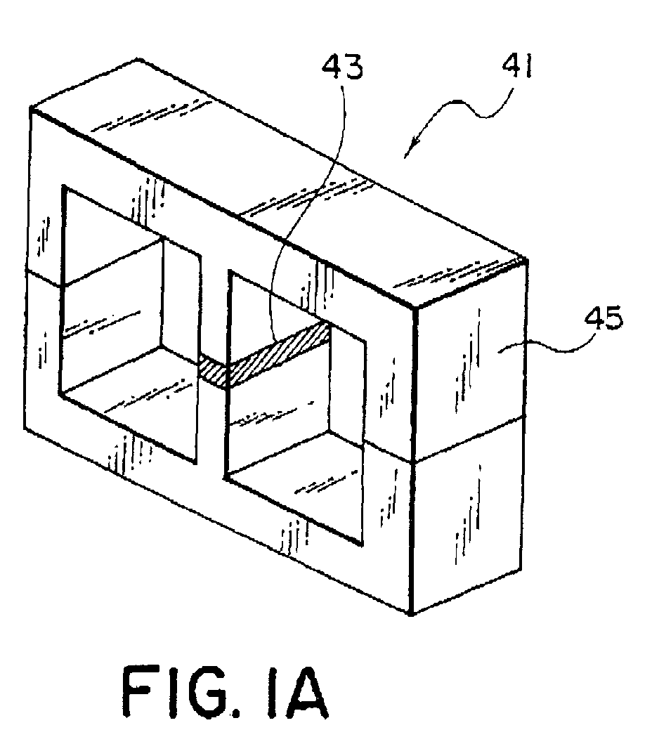
Fig. 1A is a schematic perspective view of an EE type Mn-Zn ferrite
magnetic core according to Examples 1 to 3;
Fig. 1 B is a front view of an inductor component shown in Fig. 1A;
Fig. 2 is a graph showing the results of repeated measurements of
direct current superimposition carried out while a ferrite magnet having a
coercive force of 3 kOe is inserted into a gap portion of a Mn-Zn ferrite maghetic
core in Example 1;
Fig. 3 is a graph showing the results of repeated measurements of
direct current superimposition carried out while a Sm-Fe-N bonded magnet
having a coercive force of 5 kOe is inserted into a gap portion of a Mn-Zn ferrite
magnetic core in Example 1;
Fig. 4 is a graph showing the results of repeated measurements of
direct current superimposition carried out while a Sm-Fe-N bonded magnet
having a coercive force of 11 kOe is inserted into a gap portion of a Mn-Zn
ferrite magnetic core in Example 1;
Fig. 5 is a graph showing the results of repeated measurements of
direct current superimposition carried out while a Sm-Fe-N bonded magnet
having a coercive force of 15 kOe is inserted into a gap portion of a Mn-Zn
ferrite magnetic core in Example 1;
Fig. 6 is a perspective view of a Sendust magnetic core having a
toroidal shape in Example 2;
Fig. 7 is a graph showing the comparison among direct current
superimposition characteristics of results of a Mn-Zn ferrite magnetic core with
no magnet being inserted, a Mn-Zn ferrite magnetic core with a Sm-Fe-N
bonded magnet being inserted, and a Sendust magnetic core in Example 2;
Fig. 8 is a perspective view of a toroidal core used for a choke coil
according to an embodiment of the present invention;
Fig. 9 is a perspective view of a choke coil configured by applying a coil
to the toroidal core in Fig. 8;
Fig. 10 is a graph showing measurement data of the direct current
superimposition characteristic regarding a thin plate magnet composed of a
Sm2Co17 magnet and a polyimide resin in Example 8;
Fig. 11 is a graph showing measurement data of the direct current
superimposition characteristic regarding a thin plate magnet composed of a
Sm2Co17 magnet and an epoxy resin in Example 8;
Fig. 12 is a graph showing measurement data of the direct current
superimposition characteristic regarding a thin plate magnet composed of a
Sm2Co17N magnet and a polyimide resin in Example 8;
Fig. 13 is a graph showing measurement data of the direct current
superimposition characteristic regarding a thin plate magnet composed of a Ba
ferrite magnet and a polyimide resin in Example 8;
Fig. 14 is a graph showing measurement data of the direct current
superimposition characteristic regarding a thin plate magnet composed of a
Sm2Co17 magnet and a polypropylene resin in Example 8;
Fig. 15 is a graph showing measurement data of the direct current
superimposition characteristic before and after the reflow, in the case where a
thin plate magnet made of Sample 2 or 4 is used and in the case where no thin
plate magnet is used, in Example 14;
Fig. 16 is a graph showing magnetizing magnetic fields and the direct
current superimposition characteristic of a Sm2Co17 magnet-epoxy resin thin
plate magnet in Example 20;
Fig. 17 is a perspective external view of an inductor component
including a thin plate magnet according to Example 21 of the present invention;
Fig. 18 is a perspective exploded view of the inductor component
shown in Fig. 17;
Fig. 19 is a graph showing the direct current superimposed inductance
characteristic of the inductor component shown in Fig. 17;
Fig. 20 is a perspective external view of an inductor component
including a thin plate magnet according to Example 22 of the present invention;
Fig. 21 is a perspective exploded view of the inductor component
shown in Fig. 20;
Fig. 22 is a perspective external view of an inductor component
including a thin plate magnet according to Example 23 of the present invention;
Fig. 23 is a perspective exploded view of the inductor component
shown in Fig. 22;
Fig. 24 is a graph showing the direct current superimposed inductance
characteristic of the inductor component shown in Fig. 22;
Fig. 25A is a drawing for explaining a working region of a conventional
inductor component;
Fig. 25B is a drawing for explaining a working region of the inductor
component shown in Fig. 22;
Fig. 26 is a perspective external view of an embodiment of an inductor
component including a thin plate magnet according to Example 24 of the
present invention;
Fig. 27 is a perspective exploded view of the inductor component
shown in Fig. 26;
Fig. 28 is a perspective external view of an inductor component
including a thin plate magnet according to Example 25 of the present invention;
Fig. 29 is a perspective exploded view of the inductor component
shown in Fig. 28;
Fig. 30 is a graph showing the direct current superimposed inductance
characteristic of the inductor component shown in Fig. 28;
Fig. 31A is a drawing for explaining a working region of a conventional
inductor component;
Fig. 31 B is a drawing for explaining a working region of the inductor
component shown in Fig. 28;
Fig. 32 is a perspective external view of an embodiment of an inductor
component including a thin plate magnet according to Example 26 of the
present invention;
Fig. 33 is a perspective configuration view of a core and a thin plate
magnet constituting a magnetic path of the inductor component shown in Fig.
32;
Fig. 34 is a graph showing the direct current superimposed inductance
characteristic of the inductor component shown in Fig. 32;
Fig. 35 is a perspective external view of an embodiment of an inductor
component including a thin plate magnet according to Example 27 of the
present invention;
Fig. 36 is a perspective configuration view of a core and a thin plate
magnet constituting a magnetic path of the inductor component shown in Fig.
35; and
Fig. 37 is a graph showing the direct current superimposed inductance
characteristic of the inductor component shown in Fig. 35.
DESCRIPTION OF THE PREFERRED EMBODIMENTS
The present invention will now be further specifically described.
A magnetic core according to the present invention includes at least
one gap in a magnetic path, and a permanent magnet inserted in the gap, and
has an alternating current magnetic permeability at 20 kHz of 45 or more in a
magnetic field of 120 Oe under application of direct current, and a core loss
characteristic of 100 kW/m3 or less under the conditions of 20 kHz and the
maximum magnetic flux density of 0.1 T.
Preferably, the magnetic core is made of Ni-Zn ferrite or Mn-Zn ferrite,
and the magnet is a bonded magnet composed of a rare-earth magnet powder
and binder.
Furthermore, regarding the magnetic core, preferably, the bonded
magnet contains the rare-earth magnet powder having an average particle
diameter of more than 0 µm, but 10 µm or less and 5 to 30 vol% of binder, and
has a resistivity of 1 Ω·cm or more and an intrinsic coercive force of 5 kOe or
more.
An inductor component according to the present invention is configured
by applying at least one turn of coil to the aforementioned magnetic core.
This is because the magnet characteristic necessary for achieving
superior direct current superimposition characteristic is an intrinsic coercive
force rather than an energy product and, therefore, even when a permanent
magnet having a high resistivity is used, sufficiently high direct current
superimposition characteristic can be achieved as long as the intrinsic coercive
force is high.
The magnet having a high resistivity and high intrinsic coercive force,
can be generally realized by a rare-earth bonded magnet produced by mixing a
rare-earth magnet powder and binder and by molding the resulting mixture,
although the composition is not specifically limited as long as the magnet
powder has a high coercive force. The kind of the rare-earth magnet powder
may be any of Sm-Co-base, Nd-Fe-B-base, and Sm-Fe-N-base. However,
since the strength of the bias magnetic field is determined depending on the
strength of the remanent magnetization of the powder, and the stability of the
magnetic characteristics are determined depending on the coercive force, the
kind of the magnet powder must be chosen depending on the kind of the
magnetic core.
In the present invention, as the material for the magnetic core for choke
coil and transformer, Mn-Zn ferrite or Ni-Zn ferrite having a low core loss is used,
and the magnetic core includes at least one gap in a magnetic path and a
permanent magnet inserted in the gap.
The shape of the magnetic core is not specifically limited and, therefore,
the present invention can be applied to magnetic cores having any shape, for
example, toroidal magnetic cores, EE type magnetic cores, and El type
magnetic cores. The gap length is not specifically limited, although when the
gap length is excessively reduced, the direct current superimposition
characteristic is degraded, and when the gap length is excessively increased,
the magnetic permeability is excessively reduced and, therefore, the gap length
to be formed is inevitably determined.
Regarding the characteristics required of the permanent magnet to be
inserted into the gap, when the intrinsic coercive force is less than 5 kOe,
magnetization disappears due to a direct current magnetic field applied to the
magnetic core and, therefore, a coercive force equivalent to, or more than, 5
kOe is required. The greater resistivity is the better. However, the resistivity
does not become a primary factor of degradation of the core loss as long as the
resistivity is 1 Ω·cm or more. When the average particle diameter of the
powder substantially exceeds 10 µm, the core loss characteristics are degraded
and, therefore, the average particle diameter of the powder is preferably 10 µm
or less.
Next, specific examples according to the present invention will be
described.
(Example 1)
In the following Example, each of a Sm-Fe-N bonded magnet and ferrite
magnet was inserted into a part of the magnetic path of a Mn-Zn ferrite
magnetic core, and the respective direct current superimposition characteristics
were measured and comparisons were conducted.
The ferrite magnet core used in the experiment was a EE type magnetic
core made of Mn-Zn ferrite material and having a magnetic path length of 7.5
cm and an effective cross-sectional area of 0.74 cm2, and the central leg of the
EE type magnetic core was processed to have a gap of 3.0 mm.
A Sm-Fe-N magnet powder (average particle diameter of the powder of
about 3 µm) and a binder (epoxy resin) were mixed and die molding or
compacting was carried out without magnetic field and, therefore, a bonded
magnet was produced. The amount of the binder was 5 wt% of the total
weight. The resulting bonded magnet was processed to have a shape of the
cross-section of the central leg of the ferrite magnet core and a height of 3.0
mm.
The bonded magnet and the ferrite magnet were magnetized with an
electromagnet in the direction of the magnetic path, and were inserted into the
gap portion so as to produce magnetic cores. Then 120 turns of coil was
applied to each of the magnet cores and, therefore, an inductor component was
produced. The shapes of these inductor components are shown in Figs. 1A
and 1B. In Figs. 1A and 1 B, reference numeral 43 (diagonally shaded area)
denotes a magnet,
reference numeral 45 denotes a ferrite magnet core, and
reference numeral 47 denotes coiled portions, Regarding the inserted Sm-Fe-N
bonded magnet, samples were prepared by changing the strength of the
magnetic field used for magnetizing. Each sample had a coercive force and
remanent flux density shown in Table 1. The coercive force of the used ferrite
magnet was 3 kOe.
| | coercive force Hc (kOe) | residual flux density Br (G) |
| sample 1 | 5 | 950 |
| sample 2 | 11 | 2200 |
| sample 3 | 15 | 3300 |
Regarding each of the magnetic cores with respective magnets being
inserted, the direct current superimposition characteristic was measured
repeatedly with a 4284A LCR meter manufactured by Hewlet Packerd under the
conditions of an alternating current magnetic field frequency of 100 kHz and a
superimposed magnetic field of 0 to 200 Oe. At this time, the superimposed
current was applied in order to make the direction of the direct current bias
magnetic field reverse to the direction of the magnetization of the magnet
magnetized during the insertion. The measurement results are shown in Figs.
2 to 5.
As is clear from Fig. 2, regarding the magnetic core with ferrite magnet
having a coercive force of only 3 kOe being inserted, the direct current
superimposition characteristic degrades by a large degree with increase in the
number of measurements. On the contrary, as is clear from Figs. 3 to 5,
regarding the magnetic core with a Sm-Fe-N bonded magnet having a large
coercive force being inserted, no large change is observed in the repeated
measurements and, therefore, a very stable characteristic is exhibited.
From these results, the reason for the degradation of the direct current
superimposition characteristic can be assumed to be that since the ferrite
magnet had a small coercive force, reduction of magnetization or reversion of
the miniaturization occurred due to a magnetic field of the reverse direction
applied to the magnet. Furthermore, the magnet to be inserted into the
magnetic core exhibited superior direct current superimposition characteristic
when the magnet was a rare-earth bonded magnet having a coercive force of 5
kOe or more.
(Example 2)
In the following Example, the direct current superimposition
characteristics and core losses were measured and comparisons were
conducted regarding a Mn-Zn ferrite magnetic core with a magnet being
inserted into a part of the magnetic path, a Mn-Zn ferrite magnetic core having
the same composition with no magnet being inserted, and a Sendust magnetic
core.
The ferrite magnet core used in the experiment was the same with that
used in Example 1 and, therefore, was an EE type magnetic core made of Mn-Zn
ferrite material and having a magnetic path length of 7.5 cm and an effective
cross-sectional area of 0.74 cm2, and the central leg of the EE type magnetic
core was processed to have a gap of 3.0 mm. The bonded magnet was
magnetized with an electromagnet in the direction of the magnetic path, and
was inserted into the gap portion.
Regarding the Sendust magnetic core, a powder having a particle
diameter of 150 µm or less was mixed with a binder (silicone resin), and the
resulting mixture was pressed at 20 ton/cm2, and subsequently, was heat-treated
at 700°C for 2 hours so as to produce the Sendust magnetic core. The
amount of the binder was 1.5 wt% of the total weight.
Regarding the production of the magnet, a Sm-Fe-N magnet powder (in
which average particle diameter of the powder is about 3 µm) and a binder (of
epoxy resin), were mixed and die molding or compacting was carried out
without magnetic field. The amount of the binder was 10 wt% of the total
weight. The resulting bonded magnet was processed to have a shape of the
cross-section of the central leg of the ferrite magnet core and a height of 3.0
mm. The magnet characteristics were measured using a separately prepared
test piece having a diameter of 10 and a thickness of 10 with a direct current BH
tracer. AS a result, the intrinsic coercive force was 12,500 Oe and remanent
flux density was 4,000 G. At the time of the insertion, the direction of the
magnetization of the bonded magnet was specified to be reverse to the
direction of the direct current bias magnetic field in the measurement of the
alternating current magnetic permeability.
The direct current superimposition characteristic was measured with a
4284A LCR meter manufactured by Hewlet Packerd under the conditions of an
alternating current magnetic field frequency of 100 kHz and a superimposed
magnetic field of 0 to 200 Oe. The results thereof are shown in Fig. 7.
As is clear from Fig. 7, when comparison of the magnetic permeability
in a direct current superimposed magnetic field of 100 Oe is performed,
regarding the Sendust magnetic core, the magnetic permeability is less than 30,
and regarding the Mn-Zn ferrite magnetic core with no magnet, the magnetic
permeability is 30, although regarding the ferrite magnetic core with Sm-Fe-N
magnet being inserted, the magnetic permeability is 45 or more and, therefore,
superior characteristic is exhibited.
Next, the core loss characteristic was measured at room temperature
with a SY-8232 alternating current BH tracer manufactured by Iwatsu Electric
Co., Ltd., under the conditions of 20 kHz and 0.1 T. The results thereof are
shown in Table 2.
| sample | core loss (kW/m3) |
| ferrite core with magnet inserted | 24 |
| ferrite core without magnet (gap) | 8.5 |
| sendust core | 120 |
As is clear from Table 2, the magnetic core with a magnet being
inserted has a core loss of 24 kW/m3 and, therefore, the core loss is a fifth of
that of the Sendust magnetic core. Furthermore, the increase in core loss is
relatively small compared to that of the ferrite magnetic core with no magnet
being inserted.
These results show that the magnetic core with the magnet being
inserted into the gap has superior direct current superimposition characteristic
and superior core loss characteristic with a small degree of degradation.
(Example 3)
Each of Sm-Co magnet powders having an average particle diameter of
5 µm was mixed with respective epoxy resins as a binder in an amount of 2 wt%,
5 wt%, 10 wt%, 20 wt%, 30 wt%, or 40 wt% of the total weight. Then, die
molding was carried out and, therefore, a bonded magnet having a size of 7 ×
10 mm and a height of 3.0 mm was produced.
The resulting bonded magnet was magnetized with an electromagnet in
the direction of the magnetic path, and was inserted into the gap portion of the
Mn-Zn ferrite magnetic core used in Example 1. Subsequently, the core loss
characteristic was measured at room temperature with a SY-8232 alternating
current BH tracer manufactured by Iwatsu Electric Co., Ltd., under the
conditions of 20 kHz and 0.1 T. Furthermore, the direct current
superimposition characteristic was measured with a 4284A LCR meter
manufactured by Hewlet Packerd under the conditions of an alternating current
magnetic field frequency of 100 kHz and a superimposed magnetic field of 0 to
200 Oe. These measurement data are shown in Table 3.
| amount of binder (wt%) | resistivity (Ω·cm) | core loss (kW/m3) | residual flux density Br (G) | permeability µ 100 kHz |
| 2 | 2.0 x 10⁻³ | 230 | 4600 | 52 |
| 5 | 1.0 | 72 | 3800 | 50 |
| 10 | 2.5 | 40 | 3000 | 50 |
| 20 | 12.5 | 32 | 1800 | 48 |
| 30 | 5.0 x 10² | 28 | 1250 | 40 |
| 40 | 2.5 x 10⁴ | 26 | 850 | 12 |
As is clear from Table 3, the core loss decreases with increase in an
amount of binder, and the sample containing 2 wt% of binder exhibits a very
large core loss as 200 kW/m3 or more.
The reason therefor is assumed to be that since the resistivity of the
sample containing 2 wt% of binder is very small as 2.0 × 10⁻³ Ω·cm, an eddy-current
is increased and, therefore, the core loss is increased.
The sample containing 40 wt% of binder exhibits very small magnetic
permeability in a direct current superimposed magnetic field of 100 Oe. The
reason therefor is assumed to be that since the remanent magnetization of the
bonded magnet is reduced due to large amounts of binder, the bias magnetic
field is reduced and the direct current superimposition characteristic is not
improved by a large degree.
The aforementioned results show that superior direct current
superimposition characteristic can be achieved by inserting the bonded magnet
containing the binder in an amount of 5 wt% or more, but 30 wt% or less and
having a resistivity of 1 Ω·cm or more into the gap portion, and furthermore, the
magnetic core has a core loss characteristic with a small degree of degradation
and, therefore, superior magnetic core can be produced.
(Example 4)
A sintered Sm-Co magnet having an energy product of about 28 MGOe
was roughly pulverized, and thereafter, was classified into powders having the
maximum particle diameter of 100 µm or less, 50 µm or less, and 30 µm or less
with a standard sieve. Furthermore, a part of the roughly pulverized powder
was finely pulverized in an organic solvent with a ball mill, and each of the
powders having the maximum particle diameter of 10 µm or less and 5 µm or
less was prepared from the resulting powder with a cyclone.
Each of the resulting magnet powders was mixed with 10 wt% of epoxy
resin as a binder, and a bonded magnet was produced by die molding so as to
have a size of 7 × 10 mm and a height of 0.5 mm. The characteristics of the
bonded magnet were measured using a separately prepared test piece in a
manner similar to that in Example 1. As a result, the intrinsic coercive forces of
all test pieces were 5 kOe or more regardless of the maximum particle diameter
of the powder. According to the result of the measurement of the resistivity, all
magnets showed values of 1 Ω·cm or more.
Subsequently, the produced bonded magnet was inserted into the gap
portion of the Mn-Zn ferrite magnetic core used in Example 1. Then, the
permanent magnet was magnetized in the same manner with that in Example 1,
and the core loss was measured under the conditions of 20 kHz and 0.1 T.
Herein, in the same manner with that in Example 1, the permanent magnet to
be inserted was exchanged, while the same ferrite magnetic core was used,
and the core loss was measured. The results thereof are shown in Table 4.
| particle size | core loss (kW/m3) |
| -5µm | 32 |
| -10µm | 40 |
| -30µm | 105 |
| -50µm | 160 |
| -100µm | 200 |
As is clear from Table 4, the core loss rapidly increases when the
maximum particle diameter of the magnet powder exceeds 10 µm. This result
shows that further superior core loss characteristic is exhibited when the particle
diameter of the magnet powder is 10 µm or less.
As described above, according to Examples 1 to 3 of the present
invention, the magnetic core having superior direct current superimposition
characteristic and core loss characteristic can be produced with ease at low
cost.
Next, another magnetic core according to the present invention will now
be described. Another magnetic core according to the present invention is a
magnetic core having at least one gap in a magnetic path, and including a
permanent magnet as a magnet for magnetic bias in the neighborhood of the
gap in order to apply magnetic bias from both ends of the gap. The
aforementioned magnetic core is a dust core, and the aforementioned
permanent magnet is a bonded magnet composed of a rare-earth magnet
powder having an intrinsic coercive force of 15 kOe or more, a Curie point of
300°C or more, and an average particle diameter of the powder of 2.0 to 50 µm
and a resin.
Preferably, the bonded magnet as the magnet for magnetic bias
contains 10 vol% or more of the resin and has a resistivity of 0.1 Ω·cm or more.
The initial permeability of the dust core is preferably 100 or more.
In addition, according to the present invention, an inductor component
can be configured by applying at least one coil having at least one turn to the
magnetic core including a magnet for magnetic bias.
The inductor components include coils, choke coils, transformers, and
other components indispensably including, in general, a magnetic core and a
coil.
By using the dust core and the rare-earth bonded magnet, the magnetic
core having superior direct current superimposition characteristic and core loss
characteristic can be produced, and the magnetic core is used for coils and
transformers.
In the present invention, research was conducted regarding the
combination of the permanent magnet to be inserted and the core, and resulted
in the discovery that when the dust core, preferably having an initial
permeability of 100 or more, was used as the core, and the permanent magnet
having a resistivity of 0.1 Ω·cm or more and an intrinsic coercive force of 15
kOe or more was used as the magnet to be inserted into the gap of the core,
superior direct current superimposition characteristic could be achieved and the
magnetic core having a core loss characteristic with no degradation could be
produced. This is based on the finding of the fact that the magnet
characteristic necessary for achieving superior direct current superimposition
characteristic is an intrinsic coercive force rather than an energy product and,
therefore, sufficiently high direct current superimposition characteristic can be
achieved as long as the intrinsic coercive force is high, even when a permanent
magnet having a high resistivity is used.
The magnet having a high resistivity and high intrinsic coercive force
can be generally realized by the rare-earth bonded magnet, and the bonded
magnet is produced by mixing the rare-earth magnet powder and the binder and
by molding the resulting mixture. However, any composition may be used as
long as the magnet powder has a high coercive force. The kind of the rare-earth
magnet powder may be any of SmCo-base, NdFeB-base, and SmFeN-base,
although in consideration of thermal demagnetization during the use, the
magnet must has a Tc of 300°C or more and a coercive force of 5 kOe or more.
As the resin, thermoplastic resins and thermosetting resins may be used, and
an increase in eddy-current loss was prevented by the use of these resins.
The shape of the dust core is not specifically limited, although toroidal
cores are generally used, and pot cores may be used. Each of these cores
includes at least one gap in the magnetic path, and the permanent magnet is
inserted into the gap. The gap length is not specifically limited, although when
the gap length is excessively reduced, the direct current superimposition
characteristic is degraded, and when the gap length is excessively increased,
the magnetic permeability is excessively reduced and, therefore, the gap length
to be formed is inevitably determined.
The value of the initial permeability before the formation of the gap is
important, and since when the initial permeability is excessively low, the bias
due to the magnet is not effective, the initial permeability must be 100 or more.
Regarding the characteristics required of the permanent magnet to be
inserted into the gap, when the intrinsic coercive force is 15 kOe or less, the
coercive force disappears due to the direct current magnetic field applied to the
magnetic core and, therefore, the permanent magnet must have the coercive
force of 15 kOe or more. Furthermore, the higher resistivity is the better, and
when the resistivity is 0.1 Ω·cm or more, the core loss characteristic is excellent
up to high frequencies.
When the average maximum particle diameter of the magnet powder is
50 µm or more, the core loss characteristic is degraded regardless of increase
in the resistivity of the core and, therefore, the average maximum particle
diameter of the powder is preferably 50 µm or less. However, when the
minimum particle diameter becomes 2.0 µm or less, the magnetization is
reduced remarkably due to oxidation of the powder during kneading of the
powder and the resin and, therefore, the particle diameter must be 2.0 µm or
more.
The amount of the resin must be 10 vol% or more in order to prevent an
increase in core loss.
Other Examples according to the present invention will be described
below.
(Example 5)
A sintered material was formed from a powder of pulverized ingot of
Sm2Co17 by common powder metallurgy, and the resulting sintered material
was subjected to the heat treatment for making into a magnet. Subsequently,
fine pulverization was performed so as to prepare magnet powders having
average particle diameters of about 3.5 µm, 4.5 µm, 5.5 µm, 6.5 µm, 7.5 µm,
8.5 µm, and 9.5 µm. Each of these magnet powders was subjected to an
appropriate coupling treatment, and was mixed with 40 vol% of epoxy resin as a
thermosetting resin. The resulting mixture was molded using a die under
application of a pressure of 3 t/cm2 and, therefore, a bonded magnet was
produced. Herein, the bonded magnet was molded using the die having the
same cross-sectional shape with that of the toroidal dust core 55 shown in Fig.
8. On the other hand, the intrinsic coercive force iHc was measured using a
separately prepared test piece (TP) having a diameter of 10 and a thickness of
10 with a direct current BH tracer. The results thereof are shown in Table 5.
As the dust core, a Fe-Al-Si magnetic alloy (trade name of Sendust)
powder was molded into a toroidal core 55 having a size of 27 mm in external
diameter, 14 mm in inner diameter, and 7 mm in thickness. The initial
permeability of this core was 120.
This toroidal core was processed to have a gap of 0.5 mm. The
bonded
magnet 57 produced as described above was inserted into the
aforementioned gap portion. The
magnet 57 was magnetized by an
electromagnet in the direction of the magnetic path of the
core 55. Thereafter,
a
coil 59 was applied as shown in Fig. 9, and the direct current superimposition
characteristic was measured. The applied direct current was 150 Oe in terms
of direct current magnetic field. The measurement was repeated ten times.
The results thereof are shown in Table 5. The measurement results regarding
the core with no magnet being inserted into the gap are also shown side by side
in Table 5 for purposes of comparison.
| | without magnet | particle diameter of magnet powder (µm) |
| | | 3.5 | 4.5 | 5.5 | 6.5 | 7.5 |
| iHc (Oe) of TP | - | 10 | 14 | 17 | 19 | 20 |
| µ at 150 Oe | 20 | 24 | 25 | 25 | 26 | 25 |
| µ after 10 times measurement | 20 | 20 | 21 | 24 | 25 | 25 |
As is clear from Table 5, when the coercive force is 15 kOe or more, the
degradation of the direct current superimposition characteristic does not occur
even if the direct current magnetic field was applied repeatedly.
(Example 6)
A SmFe powder produced by a reduction and diffusion method was
finely pulverized into 3 µm, and subsequently, a nitriding treatment was
performed and, therefore, a Sm-Fe-N powder was prepared as a magnet
powder. 3 wt% of Zn powder was mixed into the resulting powder, and the
resulting mixture was heat-treated at 500°C for 2 hours in Ar. The powder
characteristic thereof was measured with VSM, and as a result, the coercive
force was about 20 kOe.
Then, 45 vol% of 6 nylon as a thermoplastic resin was mixed with the
magnet powder to form a mixture. The resulting mixture was hot kneaded at
230°C, was hot pressed at the same temperature so as to have a thickness of
0.2 mm and, therefore, a sheet-like bonded magnet was produced.
The bonded magnet sheet was punched into a disk of 10 mm in
diameter, and the disks were stacked to have a thickness of 10 mm. The
magnetic characteristic of the stacked disks was measured, and as a result, the
intrinsic coercive force was about 18 kOe. The resistivity was measured with
the result of 0.1 Ω·cm or more.
On the other hand, regarding the dust core, each of toroidal dust cores
having an initial permeability of 75, 100, 150, 200, or 300 was produced in the
same manner with that in Example 5 by changing the shape of the Sendust
powder and the filling factor of the powder.
Then, gap lengths were adjusted in order that the initial permeability
become within 50 to 60 at any level of the dust cores having different initial
permeability.
The bonded magnet was inserted into the gap with no clearance.
Therefore, the magnet sheets were inserted while being superimposed or
polished if necessary.
Table 6 shows the measurement results of the magnetic permeability µe
in the direct current superimposed magnetic field of 150 Oe. The core loss
characteristic at 20 kHz and 100 mT is also shown. The dust core having an
initial permeability of 75 exhibits a direct current superimposition characteristic
µe of 16 and a core loss of 100
| characteristic | permeability of dust core (-) |
| | 75 | 105 | 150 | 200 | 300 |
| DC superposition characteristic µe(-) | 18 | 26 | 28 | 30 | 33 |
| core loss (kW/m3) | 90 | 100 | 120 | 150 | 160 |
As is clear from Table 6, when the initial permeability of the dust core
becomes less than 100, improvement of the superimposition characteristic is
not observed. This shows that when the initial permeability of the dust core is
excessively reduced, the flux of the magnet takes a shortcut and does not pass
through the core, and, therefore, the initial permeability of the core must be at
least 100.
Another embodiment according to the present invention will now be
described.
In the magnetic core according to the present invention, a thin plate
magnet is used. This thin plate magnet contains one kind of resin and a
magnet powder dispersing in the resin, and the resin is selected from the group
consisting of poly(amide-imide) resins, polyimide resins, epoxy resins,
poly(phenylene sulfide) resins, silicone resins, polyester resins, aromatic
polyamides, and liquid crystal polymers. The resin content is 30 vol% or more,
and the total thickness is 500 µm or less. Herein, the magnet powder
preferably has an intrinsic coercive force of 10 kOe or more, Tc is 500°C or
more, and an average particle diameter of the particle of 2.5 to 50 µm.
In the thin plate magnet according to the present invention, the magnet
powder may be a rare-earth magnet powder.
The thin plate magnet preferably has the surface glossiness of 25% or
more.
The thin plate magnet preferably has a molding compressibility of 20%
or more.
In an embodiment according to the present invention, the magnet
powder may be coated with a surfactant.
The aforementioned thin plate magnet preferably has a resistivity of 0.1
Ω·cm or more.
The magnetic core according to the present embodiment is a magnetic
core having at least one gap in a magnetic path, and including a permanent
magnet as a magnet for magnetic bias in the neighborhood of the magnetic gap
in order to apply magnetic bias from both ends of the gap. The permanent
magnet is the thin plate magnet. Preferably, the magnetic gap has a gap
length of about 500 µm or less, and the magnet for magnetic bias has a
thickness equivalent to, or less than, the gap length, and is magnetized in the
direction of the thickness.
In addition, an inductor component can be produced by applying at
least one coil having at least one turn to the magnetic core including the thin
plate magnet as a magnet for magnetic bias, and the resulting inductor
component is low-profile and exhibits an excellent direct current superimposition
characteristic and a low core loss.
Regarding the present invention, research was conducted on the
possibility of the use of a thin plate magnet having a thickness of 500 µm or less
as the permanent magnet for magnetic bias inserted into the magnet gap of the
magnetic core. As s result, superior direct current superimposition
characteristic could be achieved when the used thin plate magnet contained 30
vol% or more of specified resin, and had a resistivity of 0.1 Ω·cm or more and
an intrinsic coercive force of 10 kOe or more, and furthermore, a magnetic core
having a core loss characteristic with no degradation could be formed. This is
based on the finding of the fact that the magnet characteristic necessary for
achieving superior direct current superimposition characteristic is an intrinsic
coercive force rather than an energy product and, therefore, sufficiently high
direct current superimposition characteristic can be achieved as long as the
intrinsic coercive force is high, even when a permanent magnet having a high
resistivity is used.
The magnet having a high resistivity and high intrinsic coercive force
can be generally achieved by a rare-earth bonded magnet, and the rare-earth
bonded magnet is produced by mixing the rare-earth magnet powder and the
binder and by molding the resulting mixture. However, any composition may
be used as long as the magnet powder has a high coercive force. The kind of
the rare-earth magnet powder may be any of SmCo-base, NdFeB-base, and
SmFeN-base, although in consideration of thermal demagnetization during the
use, for example, reflow, the magnet must has a Curie point Tc of 500°C or
more and an intrinsic coercive force iHc of 10 kOe or more.
When the magnet powder is coated with a surfactant, since dispersion
of the powder in the molding becomes excellent, and the characteristics of the
magnet are improved, a magnetic core having higher characteristics can be
produced.
Any soft magnetic material may be effective as the material for the
magnetic core for a choke coil and transformer, although, in general, MnZn
ferrite or NiZn ferrite, dust cores, silicon steel plates, amorphous, etc., are used.
The shape of the magnetic core is not specifically limited and, therefore,
the present invention can be applied to magnetic cores having any shape, for
example, toroidal cores, EE cores, and El cores. The core includes at least
one gap in the magnetic path, and a thin plate magnet is inserted into the gap.
The gap length is not specifically limited, although when the gap length is
excessively reduced, the direct current superimposition characteristic is
degraded, and when the gap length is excessively increased, the magnetic
permeability is excessively reduced and, therefore, the gap length to be formed
is inevitably determined. The gap length may be limited to 500 µm or less in
order to reduce the size of the whole core.
Regarding the characteristics required of the thin plate magnet to be
inserted into the gap, when the intrinsic coercive force is 10 kOe or less,
magnetization disappears due to a direct current superimposed magnetic field
applied to the magnetic core and, therefore, a coercive force is required to be
10 kOe or more. The greater resistivity is the better. However, the resistivity
does not become a primary factor of degradation of the core loss as long as the
resistivity is 0.1 Ω·cm or more. When the average maximum particle diameter
of the powder becomes 50 µm or more, the core loss characteristics are
degraded and, therefore, the maximum average particle diameter of the powder
is preferably 50 µm or less. When the minimum particle diameter becomes 2.5
µm or less, the magnetization is reduced remarkably due to oxidation of the
powder during heat treatment of the powder and reflow. Therefore, the particle
diameter must be 2.5 µm or more.
Another embodiment according to the present invention will be
described below.
(Example 7)
A Sm2Co17 magnet powder and a polyimide resin were hot-kneaded by
using a Labo Plastomill as a hot kneader. The kneading was performed at
various resin contents chosen within the range of 15 vol% to 40 vol%. The
molding of the resulting hot-kneaded material into a thin plate magnet of 0.5 mm
was attempted by using a hot-pressing machine. As a result, the resin content
had to be 30 vol% or more in order to perform the molding. Regarding the
present embodiment, the above description is only related to the results on the
thin plate magnet containing a polyimide resin. However, results similar to
those described above were derived from each of the thin plate magnets
containing an epoxy resin, poly(phenylene sulfide) resin, silicone resin,
polyester resin, aromatic polyamide, or liquid crystal polymer other than the
polyimide resin.
(Example 8)
Each of the magnet powders and each of the resins were hot-kneaded
at the compositions shown in the following Table 7 by using a Labo Plastomill.
Each of the set temperature of the Labo Plastomill during operation was
specified to the
temperature 5°C higher than the softening temperature of each
of the resins.
| Composition of Thin Plate Magnet of Example 8 |
| | composition | iHc (kOe) | mixing ratio (weight part) |
| 1 ○ | Sm2Co17 magnet powder | 15 | 100 |
| polyimide resin | - | 50 |
| 2 ○ | Sm2Co17 magnet powder | 15 | 100 |
| epoxy resin | - | 50 |
| 3 ○ | Sm2Fe17N magnet powder | 10.5 | 100 |
| polyimide resin | - | 50 |
| 4 ○ | Ba Ferrite Magnet Powder Ba | 4.0 | 100 |
| polyimide resin | - | 50 |
| 5 ○ | Sm2Co17 magnet powder | 15 | 100 |
| polypropylene resin | - | 50 |
The resulting material hot-kneaded with the Labo Plastomill was die-molded
into a thin plate magnet of 0.5 mm by using a hot-pressing machine
without magnetic field. This thin plate magnet was cut so as to have the same
cross-sectional shape with that of the central magnetic leg of the E type ferrite
core 45 shown in Figs. 1A and 1 B.
Subsequently, as shown in Figs. 1A and 1B, a central leg of an EE type
core was processed to have a gap of 0.5 mm. The EE type core was made of
common Mn-Zn ferrite material and had a magnetic path length of 7.5 cm and
an effective cross-sectional area of 0.74 cm2. The thin plate magnet 43
produced as described above was inserted into the gap portion and, therefore,
a magnetic core having a magnetic bias magnet 43 was produced. In the
drawing, reference numeral 43 denotes the thin plate magnet and reference
numeral 45 denotes the ferrite core. The magnet 43 was magnetized in the
direction of the magnetic path of the core 45 with a pulse magnetizing
apparatus, a coil 47 was applied to the core 45, and an inductance L was
measured with a 4284 LCR meter manufactured by Hewlet Packerd under the
conditions of an alternating current magnetic field frequency of 100 kHz and a
superimposed magnetic field of 0 to 200 Oe. Thereafter, the inductance L was
measured again after keeping for 30 minutes at 270°C in a reflow furnace, and
this measurement was repeated five times. At this time, the direct current
superimposed current was applied and, therefore, the direction of the magnetic
field due to the direct current superimposition was reverse to the direction of the
magnetization of the magnetic bias magnet. The permeability was calculated
from the resulting inductance L, core constants (core size, etc.), and the number
of turns of coil and, therefore, the direct current superimposition characteristic
was determined. Figs. 10 to 14 show the direct current superimposition
characteristics of each cores based on the five times of measurements.
As is clear from Fig. 14, the direct current superimposition characteristic
is degraded by a large degree in the second measurement or later regarding
the core with the thin plate magnet being inserted and composed of a Sm2Co17
magnet powder dispersed in a polypropylene resin. This degradation is due to
deformation of the thin plate magnet during the reflow. As is clear from Fig. 13,
the direct current superimposition characteristic is degraded by a large degree
with increase in number of measurements regarding the core with the thin plate
magnet being inserted, while this thin plate magnet is composed of Ba ferrite
having a coercive force of only 4 kOe dispersed in a polyimide resin. On the
contrary, as is clear from Figs. 10 to 12, large changes are not observed in the
repeated measurements and very stable characteristics are exhibited regarding
the cores with the thin plate magnets being inserted, while the thin plate
magnets use the magnet powder having a coercive force of 10 kOe or more and
a polyimide or epoxy resin. From the results, the reason for the degradation of
the direct current superimposition characteristic can be assumed that since the
Ba ferrite thin plate magnet has a small coercive force, reduction of
magnetization or inversion of magnetization is brought about by a magnetic field
in the reverse direction applied to the thin plate magnet. Regarding the thin
plate magnet to be inserted into the core, when the thin plate magnet has a
coercive force of 10 kOe or more, superior direct current superimposition
characteristic is exhibited. Although not shown in the present embodiment, the
effects similar to the aforementioned effects were reliably achieved regarding
combinations other than that in the present embodiment and regarding thin
plate magnets produced by using a resin selected from the group consisting of
poly(phenylene sulfide) resins, silicone resins, polyester resins, aromatic
polyamides, and liquid crystal polymers.
(Example 9)
Each of the Sm
2Co
17 magnet powders and 30 vol% of poly(phenylene
sulfide) resin were hot-kneaded using a Labo Plastomill. Each of the magnet
powders had a particle diameter of 1.0 µm, 2.0 µm, 25 µm, 50 µm, or 55 µm.
Each of the resulting materials hot-kneaded with the Labo Plastomill was die-molded
into a thin plate magnet of 0.5 mm with a hot-pressing machine without
magnetic field. This
thin plate magnet 43 was cut so as to have the same
cross-sectional shape with that of the central leg of the E
type ferrite core 45
and, therefore, a core as shown in Figs. 1A and 1 B was produced.
Subsequently, the
thin plate magnet 43 was magnetized in the direction of the
magnetic path of the core 45 with a pulse magnetizing apparatus, a
coil 47 was
applied to the
core 45, and a core loss characteristic was measured with a SY-8232
alternating current BH tracer manufactured by Iwatsu Electric Co., Ltd.,
under the conditions of 300 kHz and 0.1 T at room temperature. The results
thereof are shown in Table 8. As is clear from Table 8, superior core loss
characteristics were exhibited when the average particle diameters of the
magnet powder used for the thin plate magnet were within the range of 2.5 to
50 µm.
| Measurement of Loss in Example 9 |
| particle diameter (µm) | 2.0 | 2.5 | 25 | 50 | 55 |
| core loss (kW/m3) | 670 | 520 | 540 | 555 | 790 |
Hot-kneading of 60 vol% of Sm
2Co
17 magnet powder and 40 vol% of
polyimide resin was performed by using a Labo Plastomill. Moldings of 0.3
mm were produced from the resulting hot-kneaded materials by a hot-pressing
machine while the pressures for pressing were changed. Subsequently,
magnetization was performed with a pulse magnetizing apparatus at 4T and,
therefore, thin plate magnets were produced. Each of the resulting thin plate
magnets had a glossiness of within the range of 15% to 33%, and the
glossiness increased with increase in pressure of the pressing. These
moldings were cut into 1 cm × 1 cm, and the flux was measured with a TOEI
TDF-5 Digital Flux meter. The measurement results of the flux and glossiness
are shown side by side in Table 9.
| Measurement of Flux in Example 10 |
| glossiness (%) | 15 | 21 | 23 | 26 | 33 | 45 |
| flux (Gauss) | 42 | 51 | 54 | 99 | 101 | 102 |
As shown in Table 9, the thin plate magnets having a glossiness of 25%
or more exhibit superior magnetic characteristics. The reason therefor is that
the filling factor becomes 90% or more when the produced thin plate magnet
has a glossiness of 25% or more. Although only the results of experiments
using the polyimide resin are described in the present embodiment, the results
similar to the aforementioned results were exhibited regarding one kind of resin
selected from the group consisting of epoxy resins, poly(phenylene sulfide)
resins, silicone resins, polyester resins, aromatic polyamides, and liquid crystal
polymers other than the aforementioned resin.
(Example 11)
A Sm
2Co
17 magnet powder, RIKACOAT (polyimide resin) manufactured
by New Japan Chemical Co., Ltd., and γ-butyrolactone as a solvent were mixed
and agitated with a centrifugal deaerator for 5 minutes, and subsequently,
kneading was performed with a triple roller mill and, therefore, paste was
produced. If the paste was dried, the composition became 60 vol% of
Sm
2Co
17 magnet powder and 40 vol% of polyimide resin. The blending ratio
of the solvent, γ-butyrolactone, was specified to be 10 parts by weight relative to
the total of the Sm
2Co
17 magnet powder and RIKACOAT manufactured by New
Japan Chemical Co., Ltd., of 70 parts by weight. A green sheet of 500 µm was
produced from the resulting paste by a doctor blade method, and drying was
performed. The dried green sheet was cut into 1 cm × 1 cm, a hot press was
performed with a hot-pressing machine while the pressures for pressing were
changed, and the resulting moldings were magnetized with a pulse magnetizing
apparatus at 4T and, therefore, thin plate magnets were produced. A molding
with no hot press was also made to be a magnet by magnetization for purposes
of comparison. At this time, production was performed at the blending ratio,
although components and blending ratios other than the above description may
be applied as long as a paste capable of making a green sheet can be
produced. Furthermore, the triple roller mill was used for kneading, although a
homogenizer, sand mill, etc, may be used other than the triple roller mill. Each
of the resulting thin plate magnets had a glossiness of within the range of 9% to
28%, and the glossiness increased with increase in pressure of the pressing.
The flux of the thin plate magnet was measured with a TOEI TDF-5 Digital Flux
meter and the measurement results are shown in Table 10. Table 10 also
shows side by side the results of the measurement of compressibility in hot
press (= 1 - thickness after hot press / thickness before hot press) of the thin
plate magnet at this time.
| Measurement of Flux in Example 11 |
| glossiness (%) | 9 | 13 | 18 | 22 | 25 | 28 |
| flux (Gauss) | 34 | 47 | 51 | 55 | 100 | 102 |
| compressibility (%) | 0 | 6 | 11 | 14 | 20 | 21 |
As is clear from the aforementioned results, similarly to Example 10,
excellent magnetic characteristics can be exhibited when the glossiness is 25%
or more. The reason for this is also that the filling factor of the thin plate
magnet becomes 90% or more when the glossiness is 25% or more.
Regarding the compressibility, the results show that excellent magnetic
characteristics can be exhibited when the compressibility is 20% or more.
Although the above description is related to the results of experiments
using the polyimide resin at specified compositions and blending ratios in the
present embodiment, the results similar to the aforementioned results were
exhibited regarding one kind of resin selected from the group consisting of
epoxy resins, poly(phenylene sulfide) resins, silicone resins, polyester resins,
aromatic polyamides, and liquid crystal polymers, and blending ratios other than
those in the above description.
(Example 12)
A Sm
2Co
17 magnet powder and 0.5 wt% of sodium phosphate as a
surfactant were mixed. Likewise, a Sm
2Co
17 magnet powder and 0.5 wt% of
sodium carboxymethylcellulose were mixed, and a Sm
2Co
17 magnet powder
and sodium silicate were mixed. 65 vol% of each of these mixed powder and
35 vol% of poly(phenylene sulfide) resin were hot-kneaded by using a Labo
Plastomill. Each of the resulting materials hot-kneaded with the Labo
Plastomill was molded into 0.5 mm by hot press and, therefore, a thin plate
magnet was produced. The resulting thin plate magnet was cut so as to have
the same cross-sectional shape with that of the central magnetic leg of the E
type ferrite core 45 shown in Figs. 1A and 1 B in a manner similar to that in
Example 8. The
thin plate magnet 43 produced as described above was
inserted into the central magnetic leg gap portion of the
EE core 45 and,
therefore, a core as shown in Figs. 1A and 1B was produced. Subsequently,
the
thin plate magnet 43 was magnetized in the direction of the magnetic path
of the core 45 with a pulse magnetizing apparatus, a
coil 47 was applied to the
core 45, and a core loss characteristic was measured with a SY-8232
alternating current BH tracer manufactured by Iwatsu Electric Co., Ltd., under
the conditions of 300 kHz and 0.1 T at room temperature. The measurement
results thereof are shown in Table 11. For purposes of comparison, the
surfactant was not used, and 65 vol% of Sm
2Co
17 magnet powder and 35 vol%
of poly(phenylene sulfide) resin were kneaded with the Labo Plastomill. The
resulting hot-kneaded material was molded into 0.5 mm by hot press, and the
resulting molding was inserted into the magnetic gap of the same ferrite EE
core with that in the above description. Subsequently, this was magnetized in
the direction of the magnetic path of the core with a pulse magnetizing
apparatus, a coil was applied, and a core loss was measured. The results
thereof are also shown side by side in Table 11.
| Measurement of Core Loss in Example 12 |
| sample | core loss (kW/m3) |
| + sodium phosphate | 495 |
| + sodium carboxylmethylcellulose | 500 |
| + sodium silicate | 485 |
| no additive | 590 |
As shown in Fig. 11, excellent core loss characteristics are exhibited
when the surfactant is added. The reason for this is that by the addition of the
surfactant, coagulation of primary particles is prevented and the eddy current
loss is alleviated. Although the above description is related to the results of
addition of the phosphate in the present embodiment, similarly to the
aforementioned results, excellent core loss characteristic, i.e., iron loss
characteristic was exhibited when surfactants other than that in the above
description were added.
(Example 13)
A Sm
2Co
17 magnet powders and a polyimide resin were hot-kneaded
with a Labo Plastomill. The resulting mixture was press-molded into a thin
plate magnet of 0.5 mm in thickness with a hot-pressing machine without
magnetic field. Herein, thin plate magnets, each having a resistivity of 0.05,
0.1, 0.2, 0.5, or 1.0 Ω·cm, were produced by controlling the content of the
polyimide resin. Thereafter, this thin plate magnet was processed so as to
have the same cross-sectional shape with that of the central magnetic leg of the
E
type ferrite core 45 shown in Figs. 1A and 1 B, in a manner similar to that in
Example 8. Subsequently, the
thin plate magnet 43 produced as described
above was inserted into the magnetic gap of the central magnetic leg of the EE
type core made of MnZn ferrite material and having a magnetic path length of
7.5 cm and an effective cross-sectional area of 0.74 cm
2. The magnetization
in the direction of the magnetic path was performed with an electromagnet, a
coil 47 was applied, and a core loss characteristic was measured with a SY-8232
alternating current BH tracer manufactured by Iwatsu Electric Co., Ltd.,
under the conditions of 300 kHz and 0.1 T at room temperature. Herein the
same ferrite core was used in the measurements, and the core losses were
measured while only the magnet was changed to other magnet having a
different resistivity. The results thereof are shown in Table 12.
| Measurement of Core Loss in Example 13 |
| resistivity (Ω·cm) | 0.05 | 0.1 | 0.2 | 0.5 | 1.0 |
| core loss (kW/m3) | 1220 | 530 | 520 | 515 | 530 |
As is clear from Table 12, excellent core loss characteristics are
exhibited when the magnetic cores had a resistivity of 0.1 Ω·cm or more. The
reason for this is that the eddy current loss can be alleviated by increasing the
resistivity of the thin plate magnet.
(Example 14)
Each of the various magnet powders and each of the various resins
were kneaded, molded, and processed at the compositions shown in Table 13
by the method as described below and, therefore, samples of 0.5 mm in
thickness were produced. Herein, A Sm2Co17 powder and a ferrite powder
were pulverized powders of sintered materials. A Sm2Fe17N powder was a
powder produced by subjecting the Sm2Fe17 powder produced by a reduction
and diffusion method to a nitriding treatment. Each of the powders had an
average particle diameter of about 5 µm. Each of an aromatic polyamide resin
(6T nylon) and a polypropylene resin was hot-kneaded by using a Labo
Plastomill in Ar at 300°C (polyamide) and 250°C (polypropylene), respectively,
and was molded with a hot-pressing machine so as to produce a sample. A
soluble polyimide resin and γ-butyrolactone as a solvent were mixed and
agitated with a centrifugal deaerator for 5 minutes so as to produce a paste.
Subsequently, a green sheet of 500 µm when completed was produced by a
doctor blade method, and was dried and hot-pressed so as to produce a sample.
An epoxy resin was agitated and mixed in a beaker, and was die-molded so as
to produce a sample at appropriate cure conditions. All these samples had a
resistivity of 0.1 Ω·cm or more.
This thin plate magnet was cut into the cross-sectional shape of the
central leg of the ferrite core described below. The core was a common EE
core made of MnZn ferrite material and having a magnetic path length of 5.9 cm
and an effective cross-sectional area of 0.74 cm2, and the central leg was
processed to have a gap of 0.5 mm. The thin plate magnet produced as
described above was inserted into the gap portion, and the arrangement was as
shown in Figs. 1A and 1B (reference numeral 43 denotes a thin plate magnet,
reference numeral 45 denotes a ferrite core, and reference numeral 47 denotes
coiled portions).
Subsequently, magnetization in the direction of the magnetic path with a
pulse magnetizing apparatus was performed, and thereafter, regarding the
direct current superimposition characteristic, an effective permeability was
measured with a HP-4284A LCR meter manufactured by Hewlet Packerd under
the conditions of an alternating current magnetic field frequency of 100 kHz and
a direct current superimposed magnetic field of 35 Oe.
These cores were kept for 30 minutes in a reflow furnace at 270°C, and
thereafter, the direct current superimposition characteristic was measured again
under the same conditions.
As a comparative example, the measurement was carried out on a
magnetic core with no magnet being inserted into the gap with the result that
the characteristic did not changed between before and after the reflow, and the
effective permeability µe was 70.
Table 13 shows these results, and Fig. 7 shows direct current
superimposition characteristics of Samples 2 and 4 and Comparative example
as a part of the results. As a matter of course, superimposed direct current
was applied in order that the direction of the direct current bias magnetic field
was reverse to the direction of the magnetization of the magnet magnetized at
the time of insertion.
Regarding the core with a thin plate magnet of polypropylene resin
being inserted, the measurement could not be carried out due to remarkable
deformation of the magnet.
Regarding the core with the Ba ferrite thin plate magnet having a
coercive force of only 4 kOe being inserted, the direct current superimposition
characteristic is degraded by a large degree after the reflow. The core with the
Sm2Fe17N thin plate magnet being inserted, the direct current superimposition
characteristic is also degraded by a large degree after the reflow. On the
contrary, regarding the core with the Sm2Co17 thin plate magnet having a
coercive force of 10 kOe or more and a Tc of as high as 770°C being inserted,
degradation of the direct current superimposition characteristic is not observed
and, therefore, very stable characteristics are exhibited.
From these results, the reason for the degradation of the direct current
superimposition characteristic is assumed to be that since the Ba ferrite thin
plate magnet has a mall coercive force, reduction of magnetization or inversion
of magnetization is brought about by a magnetic field in the reverse direction
applied to the thin plate magnet, and the reason for the degradation of the
characteristics is assumed to be that although the SmFeN magnet has a high
coercive force, the Tc is as low as 470°C and, therefore, thermal
demagnetization occurs, and the synergetic effect of the thermal
demagnetization and the demagnetization caused by a magnetic field in the
reverse direction is brought about. Therefore, regarding the thin plate magnet
inserted into the core, superior direct current superimposition characteristics are
exhibited when the thin plate magnet has a coercive force of 10 kOe or more
and a Tc of 500°C or more.
Although not shown in the present embodiment, the effects similar to
those described above could be reliably achieved when the combinations were
other than those in the present embodiment, and when thin plate magnets
produced from other resins within the scope of the present invention were used.
| sample | magnet composition | iHc (kOe) | mixing ratio (weight part) | µe before reflow (at 35Oe) | µe after reflow (at 35Oe) |
| | resin composition |
| 1 ○ | Sm(Co0.742Fe0.20Cu0.055Zr0.029)7.7 | 15 | 100 | 140 | 130 |
| aromatic polyamide resin | - | 100 |
| 2 ○ | Sm(Co0.742Fe0.20Cu0.055Zr0.029)7.7 | 15 | 100 | 120 | 120 |
| soluble polyimide resin | - | 100 |
| 3 ○ | Sm(Co0.742Fe0.20Cu0.066Zr0.029)7.7 | 15 | 100 | 140 | 120 |
| epoxy resin | - | 100 |
| 4 ○ | Sm2Fe17 N magnet powder | 10 | 100 | 140 | 70 |
| aromatic polyamide resin | - | 100 |
| 5 ○ | Ba ferrite magnet powder | 4.0 | 100 | 90 | 70 |
| aromatic polyamide resin | - | 100 |
| 6 ○ | Sm(Co0.742Fe0.20Cu0.055Zr0.029)7.7 | 15 | 100 | 140 | - |
| polypropylene resin | - | 100 |
The same Sm2Co17 magnetic powder (iHc = 15 kOe) with that in
Example 14 and a soluble poly(amide-imide) resin (TOYOBO VIROMAX) were
kneaded with a pressure kneader, were diluted and kneaded with a planetary
mixer, and were agitated with a centrifugal deaerator for 5 minutes so as to
produce a paste. Subsequently, a green sheet of about 500 µm in thickness
when dried was produced from the resulting paste by a doctor blade method,
and was dried, hot-pressed, and processed to have a thickness of 0.5 mm and,
therefore, a thin plate magnet sample was produced. Herein, the content of
the poly(amide-imide) resin was adjusted as shown in Table 14 in order that the
thin plate magnets had the resistivity of 0.06, 0.1, 0.2, 0.5, and 1.0 Ω·cm.
Thereafter, these thin plate magnets were cut into the same cross-sectional
shape with that of the central leg of the core in Example 8 so as to become
samples.
Subsequently, each of the thin plate magnets produced as described
above was inserted into the gap having a gap length of 0.5 mm of the same EE
type core with that in Example 14, and the magnet was magnetized with a pulse
magnetizing apparatus. Regarding the resulting core, a core loss
characteristic was measured with a SY-8232 alternating current BH tracer
manufactured by Iwatsu Electric Co., Ltd., under the conditions of 300 kHz and
0.1 T at room temperature. Herein the same ferrite core was used in the
measurements, and the core loss was measured after only the magnet was
changed to other magnet having a different resistivity, and was inserted and
magnetized again with the pulse magnetizing apparatus.
The results thereof are shown in Table 14. An EE core with the same
gap had a core loss characteristic of 520 (kW/m3) under the same conditions,
as a comparative example.
As shown in Table 14, magnetic cores having a resistivity of 0.1 Ω·cm or
more exhibited excellent core loss characteristics. The reason therefor is
assumed to be that the eddy current loss can be alleviated by increasing the
resistivity of the thin plate magnet.
| sample | magnet composition | amount of resin (vol %) | resistivity (Ω· cm) | core loss (kW/m3) |
| 1 ○ | Sm(Co0.742Fe0.20Cu0.055Zr0.029)7.7 | 25 | 0.06 | 1250 |
| 2 ○ | 30 | 0.1 | 680 |
| 3 ○ | 35 | 0.2 | 600 |
| 4 ○ | 40 | 0.5 | 530 |
| 5 ○ | 50 | 1.0 | 540 |
As described above, the thin plate magnet of 500 µm or less can be
produced according to the present embodiment. By using this thin plate
magnet as a magnetic bias magnet, a miniaturized magnetic core can be
provided, and this magnetic core has improved direct current superimposition
characteristics at high frequencies and has characteristics with no degradation
even at a reflow temperature. Furthermore, by using this magnetic core, an
inductor element having characteristics with no degradation due to reflow and
having a capability of surface mounting can be provided.
(Example 16)
Magnet powders having different average particle diameters were
prepared from a sintered magnet (iHc = 15 kOe) having a composition
Sm(Co0.742Fe0.20Cu0.055Zr0.029)7.7 by changing pulverization times, and
thereafter maximum particle diameters were adjusted through sieves having
different meshes.
A Sm
2Co
17 magnet powder, RIKACOAT (polyimide resin) manufactured
by New Japan Chemical Co., Ltd., and γ-butyrolactone as a solvent were mixed
and agitated with a centrifugal deaerator for 5 minutes and, therefore, paste
was produced. If the paste was dried, the composition became 60 vol% of
Sm
2Co
17 magnet powder and 40 vol% of polyimide resin. The blending ratio
of the solvent, γ-butyrolactone, was specified to be 10 parts by weight relative to
the total of the Sm
2Co
17 magnet powder and RIKACOAT manufactured by New
Japan Chemical Co., Ltd., of 70 parts by weight. A green sheet of 500 µm was
produced from the resulting paste by a doctor blade method, and drying and
hot-pressing were performed. The resulting sheet was cut into the shape of
the central leg of the ferrite core, and was magnetized with a pulse magnetizing
apparatus at 4T and, therefore, a thin plate magnet were produced. The flux of
each of these thin plate magnets was measured with a TOEI TDF-5 Digital Flux
meter and the measurement results are shown in Table 15. Furthermore, the
thin plate magnet was inserted into the ferrite core in a manner similar to that in
Example 14, and direct current superimposition characteristic was measured,
and subsequently, the quantity of bias was measured. The quantity of bias
was determined as a product of magnetic permeability and superimposed
magnetic field.
| sample | average particle diameter (µm) | mesh of sieve (µm) | press pressure upon hot press (kgf/cm2) | center line average roughness (µm) | amount of flux (G) | bias amount (G) |
| 1 ○ | 2.1 | 45 | 200 | 1.7 | 30 | 600 |
| 2 ○ | 2.5 | 45 | 200 | 2 | 130 | 2500 |
| 3 ○ | 5.4 | 45 | 200 | 6 | 110 | 2150 |
| 4 ○ | 25 | 45 | 200 | 20 | 90 | 1200 |
| 5 ○ | 5.2 | 45 | 100 | 12 | 60 | 1100 |
| 6 ○ | 5.5 | 90 | 200 | 15 | 100 | 1400 |
Regarding Sample 1 having an average particle diameter of 2.1 µm, the
flux is reduced and the quantity of bias is small. The reason for this is believed
to be that oxidation of the magnet powder proceeds during production steps.
Regarding Sample 4 having a large average particle diameter, the flux is
reduced due to a low filling factor of the powder, and the quantity of bias is
reduced. The reason for the reduction of the quantity of bias is believed to be
that since the surface roughness of the magnet is coarse, adhesion with the
core is insufficient and, therefore, permeance coefficient is reduced.
Regarding Sample 5 having a small particle diameter, but having a large
surface roughness due to an insufficient pressure during the press, the flux is
reduced due to a low filling factor of the powder, and the quantity of bias is
reduced. Regarding Sample 6 containing coarse particles, the quantity of bias
is reduced. The reason for this is believed to be that the surface roughness is
coarse.
As is clear from these results, superior direct current superimposition
characteristics are exhibited when an inserted thin plate magnet has an average
particle diameter of the magnet powder of 25 µm or more, the maximum particle
diameter of 50 µm or more, and a center line average roughness of 10 µm or
less.
(Example 17)
Two magnet powders, each produced by rough pulverization of an ingot
and subsequent heat treatment, were used. One ingot was a Sm2Co17-based
ingot having a Zr content of 0.01 atomic percent and having a composition of
so-called second-generation Sm2Co17 magnet, Sm(Co0.78Fe0.11Cu0.10Zr0.01)8.2,
and the other ingot was a Sm2Co17-based ingot having a Zr content of 0.029
atomic percent and having a composition of so-called third-generation Sm2Co17
magnet, Sm(Co0.0742Fe0.20Cu0.055Zr0.029)8.2. The aforementioned second-generation
Sm2Co17 magnet powder was subjected to an age heat treatment at
800°C for 1.5 hours, and the third-generation Sm2Co17 magnet powder was
subjected to an age heat treatment at 800°C for 10 hours. By these treatments,
coercive forces measured by VSM were 8 kOe and 20 kOe regarding the
second-generation Sm2Co17 magnet powder and the third-generation Sm2Co17
magnet powder, respectively. These roughly pulverized powders were finely
pulverized in an organic solvent with a ball mill in order to have an average
particle diameter of 5.2 µm, and the resulting powders were passed through a
sieve having openings of 45 µm and, therefore, magnet powders were
produced. Each of the resulting magnet powders was mixed with 35 vol% of
epoxy resin, and the mixture was die-molded into a bonded magnet having a
shape of the central leg of the same EE core with that in Example 14 and a
thickness of 0.5 mm. The magnet characteristics were measured using a
separately prepared test piece having a diameter of 10 and a thickness of 10
with a direct current BH tracer.
The coercive forces were nearly equivalent to those of the roughly
pulverized powder. Subsequently, these magnets were inserted into the same
EE core with that in Example 14, and pulse magnetization and application of
coil were performed. Then, the effective permeability was measured with a
LCR meter under the conditions of a direct current superimposed magnetic field
of 40 Oe and 100 kHz. These cores were kept under the same conditions with
those in the reflow, that is, these cores were kept in a thermostatic chamber at
270°C for 1 hour, and thereafter, the direct current superimposition
characteristics were measured in a manner similar to that in the above
description. The results thereof are also shown in Table 16.
| Sample | µe before reflow (at 35 Oe) | µe before reflow (at 35 Oe) |
| Sm(Co0.78Fe0.11Cu0.10Zr0.01)8.2 | 120 | 40 |
| Sm(Co0.742Fe0.20Cu0.055Zr0.029)8.2 | 130 | 130 |
As is clear from Table 16, when the third-generation Sm2Co17 magnet
powder having a high coercive force is used, excellent direct current
superimposition characteristics can also be achieved even after the reflow.
The presence of a peak of the coercive force is generally observed at a specific
ratio of Sm and transition metals, although the optimum compositional ratio
varies depending on the oxygen content in the alloy as is generally known.
Regarding the sintered material, the optimum compositional ratio is verified to
vary within 7.0 to 8.0, and regarding the ingot, the optimum compositional ratio
is verified to vary within 8.0 to 8.5. As is clear from above description,
excellent direct current superimposition characteristics are exhibited even under
reflow conditions when the composition is the third-generation Sm(Cobal.Fe0.15
to 0.25Cu0.05 to 0.06Zr0.02 to 0.03)7.0 to 8.5.
(Example 18)
The magnet powder produced in Sample 3 of Example 16 was used.
This magnet powder had a composition Sm(Co0.742Fe0.20Cu0.055Zr0.029)7.7, an
average particle diameter of 5 µm, and a maximum particle diameter of 45 µm.
The surface of each of the magnet powders was coated with Zn, inorganic glass
(ZnO-B2O3-PbO) having a softening point of 400°C, or Zn and furthermore
inorganic glass (ZnO-B2O3-PbO). The thin plate magnet was produced in the
same manner with that of Sample 2 of Example 2, the resulting thin plate
magnet was inserted into the Mn-Zn ferrite core, and the direct current
superimposition characteristic of the resulting Mn-Zn ferrite core was measured
in the same manner with that in Example 16. Thereafter the quantity of bias
was determined and the core loss characteristic was measured in the same
manner with that in Example 2. The results of the comparison are shown in
Fig. 17.
Herein, Zn was mixed with the magnet powder, and thereafter, a heat
treatment was performed at 500°C in an Ar atmosphere for 2 hours. ZnO-B2O3-PbO
was heat-treated in the same manner with that of Zn except that the
heat treatment temperature was 450°C. On the other hand, in order to form a
composite layer, Zn and the magnet powder were mixed and were heat-treated
at 500°C, the resulting powder was taken out of the furnace, and the powder
and the ZnO-B2O3-PbO powder were mixed, and thereafter, the resulting
mixture was heat-treated at 450°C. The resulting powder was mixed with a
binder (epoxy resin) in an amount of 45 vol% of the total volume, and thereafter,
die-molding was performed without magnetic field. The resulting molding had
the shape of the cross-section of the central leg of the same ferrite core with
that in Example 15 and had a height of 0,5 mm. The resulting molding was
inserted into the core, and magnetization was performed with a pulse magnetic
field of about 10 T. The direct current superimposition characteristic was
measured in the same manner with that in Example 14, and the core loss
characteristic was measured in the same manner with that in Example 15.
Then, these cores were kept in a thermostatic chamber at 270°C for 30 minutes,
and thereafter, the direct current superimposition characteristic and core loss
characteristic were measured similarly to the above description. As a
comparative example, a molding was produced from the powder with no coating
in the same manner with that described above, and characteristics were
measured. The results are also shown in Table 17.
As is clear from the results, although regarding the uncoated sample,
the direct current superimposition characteristic and core loss characteristic are
degraded by a large degree due to the heat treatment, regarding the samples
coated with Zn, inorganic glass, and a composite thereof, rate of the
degradation during the heat treatment is very small compared to that of the
uncoated sample. The reason therefor is assumed to be that oxidation of the
magnet powder is prevented by the coating.
Regarding the samples containing 10 vol% or more of coating materials,
the effective permeability is low, and the strength of the bias magnetic field due
to the magnet is reduced by a large degree compared to those of other samples.
The reason therefor is believed to be that the content of the magnet powder is
reduced due to increase in amount of the coating material, or magnetization is
reduced due to reaction of the magnet powder and the coating materials.
Therefore, especially superior characteristics are exhibited when the amount of
the coating material is within the range of 0.1 to 10 wt%.
| Sample | coating layer | before reflow | after reflow |
| | Zn (vol%) | B2O3-PbO (vol%) | Zn+ B2O3-PbO (vol%) | bias amount (G) | core loss (kW/m3) | bias amount (G) | core loss (kW/m3) |
| comparative example | - | - | - | 2200 | 520 | 300 | 1020 |
| 1 | 0.1 | | | 2180 | 530 | 2010 | 620 |
| 2 | 1.0 | | | 2150 | 550 | 2050 | 600 |
| 3 | 3.0 | | | 2130 | 570 | 2100 | 580 |
| 4 | 5.0 | | | 2100 | 590 | 2080 | 610 |
| 5 | 10.0 | | | 2000 | 650 | 1980 | 690 |
| 6 | 15.0 | | | 1480 | 1310 | 1480 | 1350 |
| 7 | | 0.1 | | 2150 | 540 | 1980 | 610 |
| 8 | | 1.0 | | 2080 | 530 | 1990 | 590 |
| 9 | | 3.0 | | 2050 | 550 | 2020 | 540 |
| 10 | | 5.0 | | 2020 | 570 | 2000 | 550 |
| 11 | | 10.0 | | 1900 | 560 | 1880 | 570 |
| 12 | | 15.0 | | 1250 | 530 | 1180 | 540 |
| 13 | | | 3+2 | 2050 | 560 | 2030 | 550 |
| 14 | | | 5+5 | 2080 | 550 | 2050 | 560 |
| 15 | | | 10+5 | 1330 | 570 | 1280 | 580 |
The Sm2Co17 magnet powder of Sample 3 in Example 16 was mixed
with 50 vol% of epoxy resin as a binder, and the resulting mixture was die-molded
in the direction of top and bottom of the central leg in a magnetic field of
2 T so as to produce an anisotropic magnet. As a comparative example, a
magnet was also produced by die-molding without magnetic field. Thereafter,
each of these bonded magnets was inserted into a MnZn ferrite material in a
manner similar to that in Example 15, and pulse magnetization and application
of coil were performed. Then, the direct current superimposition characteristic
was measured with a LCR meter, and the magnetic permeability was calculated
from the core constants and the number of turns of coil. The results thereof
are shown in Table 18.
After the measurements were completed, the samples were kept under
the same conditions with those in the reflow, that is, the samples were kept in a
thermostatic chamber at 270°C for 1 hour. Thereafter, the samples were
cooled to ambient temperature and the direct current superimposition
characteristics were measured in a manner similar to that in the above
description. The results thereof are also shown in Table 18.
As is clear from Table 18, excellent direct current superimposition
characteristics are exhibited both before and after the reflow compared to that
of magnets molded without magnetic field.
| sample | µe before reflow (at 45 Oe) | µe after reflow (at 45 Oe) |
| molded within magnetic field | 130 | 130 |
| molded without magnetic field | 50 | 50 |
The Sm2Co17 magnet powder of Sample 3 in Example 16 was mixed
with 50 vol% of epoxy resin as a binder, and the resulting mixture was die-molded
without magnetic field so as to produce a magnet having a thickness of
0.5 mm. The resulting magnet was inserted into a MnZn ferrite material, and
magnetization was performed in a manner similar to that in Example 14. At
that time, the magnetic fields for magnetization were 1, 2, 2.5, 3, 5, and 10 T.
Regarding 1, 2, and 2.5 T, magnetization was performed with an electromagnet,
and regarding 3, 5, and 10 T, magnetization was performed with a pulse
magnetizing apparatus. Subsequently, the direct current superimposition
characteristic was measured with a LCR meter, and the magnetic permeability
was calculated from the core constants and the number of turns of coil. From
these results, the quantity of bias was determined by the method used in
Example 16, and the results thereof are shown in Fig. 16.
As is clear from Fig. 16, when the magnetic field is less than 2.5 T,
excellent superimposition characteristics cannot be achieved.
(Example 21)
An inductor component according to the present invention will now be
described below with reference to Figs. 17 and 18. A core 65 used in an
inductor component is made of a MnZn ferrite material and constitutes an EE
type magnetic core having a magnetic path length of 2.46 cm and an effective
cross-sectional area of 0.394 cm2. The thin plate magnet 69 having a
thickness of 0.16 mm is processed into the same shape with the cross-section
of the central leg of the E type core 65. As shown in Fig. 18, a molded coil
(resin-sealed coil (number of turns of 4 turns)) 67 is incorporated in the E type
core 65, the thin plate magnet 69 is arranged in a core gap portion, and is held
by the other core 65 and, therefore, this assembly functions as an inductor
component.
The direction of the magnetization of the thin plate magnet 69 is
specified to be reverse to the direction of the magnetic field made by the
molded coil.
The direct current superimposed inductance characteristics were
measured regarding the case where the thin plate magnet was applied and the
case where the thin plate magnet was not applied for purposes of comparison,
and the results are indicated by 73, the former, and 71, the latter, in Fig. 19.
The direct current superimposed inductance characteristic was
measured after passing through a reflow furnace (peak temperature of 270°C)
similarly to the above description. As a result, the direct current superimposed
inductance characteristic after the reflow was verified to be equivalent to that
before the reflow.
(Example 22)
Another inductor component according to the present invention will now
be described below with reference to Figs. 20 and 21. A core used in the
inductor component is made of a MnZn ferrite material and constitutes a
magnetic core having a magnetic path length of 2.46 cm and an effective cross-sectional
area of 0.394 cm2 in a manner similar to Example 21. However, an
El type magnetic core is formed and functions as an inductor component. The
steps for assembling are similar to those in Example 21, although the shape of
one ferrite core 77 is I type.
The direct current superimposed inductance characteristics are
equivalent to those in Example 21 regarding the core with the thin plate magnet
being applied and the core after passing through a reflow furnace.
(Example 23)
Another inductor component according to the present invention will now
be described below with reference to Figs. 22 and 23. A thin plate magnet
according to Example 23 of the present invention is applied to the inductor
component. A core 87 used in the inductor component is made of a MnZn
ferrite material and constitutes a UU type magnetic core having a magnetic path
length of 0.02 m and an effective cross-sectional area of 5 × 10⁻⁶ m2. As
shown in Fig. 23, a coil 91 is applied to a bobbin 89, and a thin plate magnet 93
is arranged in a gap portion when a pair of U type cores 87 are incorporated.
The thin plate magnet 93 has been processed into the same shape of the cross-section
(joint portion) of the U type core 87, and has a thickness of 0.2 mm.
This assembly functions as an inductor component having a permeability of 4 ×
10-3 H/m.
The direction of the magnetization of the thin plate magnet 93 is
specified to be reverse to the direction of the magnetic field made by the coil.
The direct current superimposed inductance characteristics were
measured regarding the case where the thin plate magnet was applied and, for
purposes of comparison, the case where the thin plate magnet was not applied.
The results are indicated by 97, the former, and 95, the latter, in Fig. 24.
The results of the aforementioned direct current superimposed
inductance characteristics are generally equivalent to enlargement of working
magnetic flux density (ΔB) of the core constituting the magnetic core, and this is
supplementally described below with reference to Figs. 25A and 25B. In Fig.
25A, 99 indicates a working range of the core relative to a conventional inductor
component, and 101 in Fig. 25B indicates a working range of the core relative to
the inductor component with the thin plate magnet according to the present
invention being applied. Regarding these drawings, 99 and 101 correspond to
95 and 97, respectively, in the aforementioned results of the direct current
superimposed inductance characteristics. In general, inductor components are
represented by the following theoretical equation (1).
ΔB = (E·ton) / (N·Ae)
wherein E denotes applied voltage of inductor component, ton denotes
voltage application time, N denotes the number of turns of inductor, and Ae
denotes effective cross-sectional area of core constituting magnetic core.
As is clear from this equation (1), an effect of the aforementioned
enlargement of the working magnetic flux density (ΔB) is proportionate to the
reciprocal of the number of turns N and the reciprocal of the effective cross-sectional
area Ae, while the former brings about an effect of reducing the
copper loss and miniaturization of the inductor component due to reduction of
the number of turns of the inductor component, and the latter contributes to
miniaturization of the core constituting the magnetic core and, therefore,
contributes to miniaturization of the inductor component by a large degree in
combination with the aforementioned miniaturization due to the reduction of the
number of turns. Regarding the transformer, since the number of turns of the
primary and secondary coils can be reduced, an enormous effect is exhibited.
Furthermore, the output power is represented by the equation (2). As
is clear from the equation, the effect of enlarging working magnetic flux density
(ΔB) affects an effect of increasing output power.
Po = κ·(ΔB)2·f
wherein Po denotes inductor output power, κ denotes proportionality
constant, and f denotes driving frequency.
Regarding the reliability of the inductor component, the direct current
superimposed inductance characteristic was measured after passing through a
reflow furnace (peak temperature of 270°C) similarly to the above description.
As a result, the direct current superimposed inductance characteristic after the
reflow was verified to be equivalent to that before the reflow.
(Example 24)
Another inductor component according to the present invention will now
be described below with reference to Figs. 26 and 27. A thin plate magnet
according to Example 24 of the present invention is applied to the inductor
component. A core used in the inductor component is made of a MnZn ferrite
material and constitutes a magnetic core having a magnetic path length of 0.02
m and an effective cross-sectional area of 5 × 10⁻⁶ m2 in a manner similar to
Example 23, or constitutes a Ul type magnetic core and, therefore, functions as
the inductor component. As shown in Fig. 27, a coil 109 is applied to a bobbin
71, and an I type core 107 is incorporated in the bobbin. Subsequently, thin
plate magnets 113 are arranged on both flange portions of the coiled bobbin (on
the portions of the I type core 107 extending off the bobbin) on a one-by-one
basis (total two magnets for both flanges), and a U type core 105 is
incorporated and, therefore, the inductor component is completed. The thin
plate magnets 113 have been processed into the same shape of the cross-section
(joint portion) of the U type core 105, and have a thickness of 0.1 mm.
The direct current superimposed inductance characteristics are
equivalent to those in Example 23 regarding the core with the thin plate magnet
being applied and the core after passing through a reflow furnace.
(Example 25)
Another inductor component according to the present invention will now
be described below with reference to Figs. 28 and 29. A thin plate magnet
according to Example 25 of the present invention is applied to the inductor
component. Four I type cores 117 used in the inductor component are made
of silicon steel and constitutes a square type magnetic core having a magnetic
path length of 0.2 m and an effective cross-sectional area of 1 × 10⁻⁴m2. As
shown in Fig. 28, type cores 117 are inserted into two coils 119 having
insulating paper on a one-by-one basis, and another two I type cores 117 are
incorporated in order to form a square type magnetic path. Magnetic cores
123 according to the present invention are arranged at the joint portion thereof
and, therefore, the square type magnetic path having a permeability of 2 × 10⁻²
H/m is formed and functions as the inductor component.
The direction of the magnetization of the thin plate magnet 123 is
specified to be reverse to the direction of the magnetic field made by the coil.
The direct current superimposed inductance characteristics were
measured regarding the case where the thin plate magnet was applied and, for
purposes of comparison, where the thin plate magnet was not applied. The
results are indicated by 127, the former, and 125, the latter, in Fig. 30.
The results of the aforementioned direct current superimposed
inductance characteristics are generally equivalent to enlargement of working
magnetic flux density (ΔB) of the core constituting the magnetic core, and this is
supplementally described below with reference to Figs. 31A and 31B. In Fig.
31A, 129 indicates a working range of the core relative to a conventional
inductor component, and 131 in Fig. 31 B indicates a working range of the core
relative to the inductor component with the thin plate magnet according to the
present invention being applied. Regarding these drawings, 129 and 131
correspond to 125 and 127, respectively, in the aforementioned results of the
direct current superimposed inductance characteristics. In general, inductor
components are represented by the following theoretical equation (1).
ΔB = (E·ton) / (N·Ae)
wherein E denotes applied voltage of inductor component, ton denotes
voltage application time, N denotes the number of turns of inductor, and Ae
denotes effective cross-sectional area of core constituting magnetic core.
As is clear from this equation (1), an effect of the aforementioned
enlargement of the working magnetic flux density (ΔB) is proportionate to the
reciprocal of the number of turns N and the reciprocal of the effective cross-sectional
area Ae, while the former brings about an effect of reducing the
copper loss and miniaturization of the inductor component due to reduction of
the number of turns of the inductor component, and the latter contributes to
miniaturization of the core constituting the magnetic core and, therefore,
contributes to miniaturization of the inductor component by a large degree in
combination with the aforementioned miniaturization due to the reduction of the
number of turns. Regarding the transformer, since the number of turns of the
primary and secondary coils can be reduced, an enormous effect is exhibited.
Furthermore, the output power is represented by the equation (2). As
is clear from the equation, the effect of enlarging working magnetic flux density
(ΔB) affects an effect of increasing output power.
Po = κ·(ΔB)2·f
wherein Po denotes inductor output power, κ denotes proportionality
constant, and f denotes driving frequency.
Regarding the reliability of the inductor component, the direct current
superimposed inductance characteristic was measured after passing through a
reflow furnace (peak temperature of 270°C) similarly to the above description.
As a result, the direct current superimposed inductance characteristic after the
reflow was verified to be equivalent to that before the reflow.
(Example 26)
Another inductor component according to the present invention will now
be described below with reference to Figs. 32 and 33. The inductor
component according to Example 26 of the present invention is composed of a
square type core 135 having rectangular concave portions, an I type core 137, a
bobbin 141 with a coil 139 being applied, and thin plate magnets 143. As
shown in Fig. 33, the thin plate magnets 143 are arranged in the rectangular
concave portions of the square type core 135, that is, at the joint portions of the
square type core 135 and the I type core 137.
Herein, the square type core 135 and I type core 137 are made of MnZn
ferrite material, and constituting the magnetic core having a shape of the two
same rectangles arranged side-by-side and having a magnetic path length of
6.0 cm and an effective cross-sectional area of 0.1 cm2.
The thin plate magnet 143 has a thickness of 0.25 mm and a cross-sectional
area of 0.1 cm2, and direction of the magnetization of the thin plate
magnet 143 is specified to be reverse to the direction of the magnetic field
made by the coil.
The coil 139 has the number of turns of 18 turns, and the direct current
superimposed inductance characteristics were measured regarding the inductor
component according to the present invention and, for purposes of comparison,
regarding the case where the thin plate magnet was not applied. The results
are indicated by 147, the former, and 145, the latter, in Fig. 34.
The direct current superimposed inductance characteristic was
measured after passing through a reflow furnace (peak temperature of 270°C)
similarly to the above description. As a result, the direct current superimposed
inductance characteristic after the reflow was verified to be equivalent to that
before the reflow.
(Example 27)
Another inductor component according to the present invention will now
be described below with reference to Figs. 35 and 36. A thin plate magnet
according to Example 27 of the present invention is applied to the inductor
component. Regarding the configuration of the inductor component, a coil 157
is applied to a convex type core 153, a thin plate magnets 159 is arranged on
the top surface of the convex portion of the convex type core 153, and these are
covered with a cylindrical cap core 155. The thin plate magnet 159 has the
same shape (0.07 mm) with the top surface of the convex portion of the convex
type core 153, and has a thickness of 120 µm.
Herein, the aforementioned convex type core 153 and cylindrical cap
core 155 are made of NiZn ferrite material, and constituting the magnetic core
having a magnetic path length of 1.85 cm and an effective cross-sectional area
of 0.07 cm2.
The direction of the magnetization of the thin plate magnet 159 is
specified to be reverse to the direction of the magnetic field made by the coil.
The coil 157 has the number of turns of 15 turns, and the direct current
superimposed inductance characteristics were measured regarding the inductor
component according to the present invention and, for purposes of comparison,
regarding the case where the thin plate magnet was not applied. The results
are indicated by 165 (the former) and 163 (the latter) in Fig. 37.
The direct current superimposed inductance characteristic was
measured after passing through a reflow furnace (peak temperature of 270°C)
similarly to the above description. As a result, the direct current superimposed
inductance characteristic after the reflow was verified to be equivalent to that
before the reflow.