JP2004247409A - Magnetic core and inductance component using the same - Google Patents
Magnetic core and inductance component using the same Download PDFInfo
- Publication number
- JP2004247409A JP2004247409A JP2003033901A JP2003033901A JP2004247409A JP 2004247409 A JP2004247409 A JP 2004247409A JP 2003033901 A JP2003033901 A JP 2003033901A JP 2003033901 A JP2003033901 A JP 2003033901A JP 2004247409 A JP2004247409 A JP 2004247409A
- Authority
- JP
- Japan
- Prior art keywords
- core
- magnetic core
- magnetic
- magnet
- gap
- Prior art date
- Legal status (The legal status is an assumption and is not a legal conclusion. Google has not performed a legal analysis and makes no representation as to the accuracy of the status listed.)
- Pending
Links
Images


Abstract
Description
【0001】
【発明の属する技術分野】
本発明は、スイッチング電源などに使用されるチョークコイル用及びトランス用磁芯に好適な磁芯およびそれを用いたインダクタンス部品に関する。
【0002】
【従来の技術】
チョークコイル用及びトランス用磁芯には、良好な直流重畳特性が求められており、高周波用の磁芯には、フェライトや圧粉磁芯が使用されている。フェライト磁芯は、初透磁率が高く飽和磁束密度が小さい、圧粉磁芯は、初透磁率が低く飽和磁束密度が高い、という材料物性に由来した特徴がある。従って、圧粉磁芯は、トロイダル形状で用いられることが多く、フェライトは、例えばE型コアの中足にギャップを挿入してEEコアで用いられることが多い。
【0003】
しかし、近年の電子機器の小型化の要請に伴う電子部品の小型化の要求により、インダクタンス部品に対して大きな重畳磁界における、高い透磁率が強く求められている。一般に、直流重畳特性を向上させるためには、飽和磁化の高い磁芯を選択する事、つまり高磁界で磁気飽和しない磁芯の選択が必須とされている。
しかし、飽和磁化は材料の組成で必然的に決まるものであり、無限に高く出来るものではない。そのため、従来の直流重畳特性を向上させる手段は、わずかな飽和磁化の向上に多大な労力が費やされている割には、直流重畳特性は期待されている程、伸びていないのが現状であった。
【0004】
その解決手段として、磁路の一箇所以上にギャップを挿入し、そのギャップに永久磁石を挿入する事が従来から検討されてきた。この方法は、直流重畳特性を向上させるには優れた方法であるが、一方で金属焼結磁石を用いると磁芯のコアロスの増大が著しく、またフェライト磁石を用いると重畳特性が安定しないなどとても実用に耐え得るものではなかった。これらを解決する手段として、例えば、特許文献1では、永久磁石として保磁力の高い希土類磁石粉末とバインダーとを混合し圧縮成形したボンド磁石を挿入することが示されており、直流重畳特性とコアの温度上昇が改善されたことが示されている。
【0005】
【特許文献1】
特開昭50−133453号公報
【0006】
【発明が解決しようとする課題】
しかし、近年、電源に対する電力変換効率向上の要求は、ますます厳しくなっており、チョークコイル用及びトランス用のコアについても、単にコア温度を測定するだけでは優劣の判断が困難なレベルとなっている。そのため、コアロス測定装置による測定結果の判断が不可欠であり、実際、本発明者等が検討を行った結果、特許文献1に示された低抗率の値では、コアロス特性が劣化する事が明らかになった。
【0007】
そこで我々は、ギャップに挿入する永久磁石として、10×79kAT/m(10kOe)以上の固有保磁力、800℃以上のキュリ温度Tc、1.0Ω・cm以上の比抵抗の永久磁石を挿入することで、コアロスを低下させることなく、良好な直流重畳特性が得られることを発見している。
【0008】
しかしながら、これらの特性値以上の要求があり、信頼性、コアロス特性、重畳特性において更なる向上を目指すためには、ギャップに挿入する永久磁石の高保磁力と高残留磁束密度、高キュリ温度Tcを合わせ持つ、磁石の開発が必要である。
【0009】
本発明の課題は、上記問題点に鑑み、優れたコアロス特性と直流重畳特性を有する、安価な磁芯およびそれを用いたインダクタンス部品を提供することである。
【0010】
【課題を解決するための手段】
本発明は、前記課題を達成するべく挿入する永久磁石について検討した結果、磁石の比抵抗が1.0Ω・cm以上の永久磁石を使用した時優れた直流重畳特性が得られ、しかもコアロス特性の劣化が生じない磁芯を形成できる事を見出した。優れた直流重畳特性を得るのに必要な磁石特性は、エネルギー積よりもむしろ固有保磁力であること見出した。
【0011】
比抵抗が高く、しかも固有保磁力が高い磁石は、一般的には希土類磁石粉末をバインダーとともに混合して成形した希土類ボンド磁石で得られる。希土類磁石粉末の種類は、SmCo系、NdFeB系、SmFeN系とあるが、リフロー条件及び耐酸化性を考慮すると、キュリ温度Tcが800℃以上、保磁力が20×79kAT/m(20kOe)以上の磁石は現状ではSm2Co17系磁石に限定される。
【0012】
そこで、我々は、Sm2Co17系磁石の検討を行った結果、Sm(Fe0.15 〜 0.25Cu0.06 〜 0.08Zr0.02 〜 0.33Co0.64 〜 0.77)7.0 〜 8.5の組成を有する磁石において、キュリ温度Tcが800℃以上、保磁力が20×79kAT/m(20kOe)以上の高特性な磁石を見出した。
【0013】
【発明の実施の形態】
本発明の実施の形態による磁芯およびそれを用いたインダクタンス部品について、以下に説明する。
【0014】
チョークコイル用及びトランス用磁芯としては、軟磁気特性を有する材料であればなんでも有効であるが、一般的には、MnZn系又はNi−Zn系フェライト、圧粉磁芯、珪素鋼板、アモルファス等が用いられる。また、磁芯の形状についても特に制限があるわけではなく、トロイダルコア、EEコア、EIコア等あらゆる形状の磁芯に本発明の適用が可能である。これらコアの磁路の少なくとも1箇所以上にギャップを設け、そのギャップに永久磁石を挿入する。ギャップ長に特に制限はないが、ギャップ長が狭すぎると直流重畳特性が劣化し、またギャップ長が広すぎると透磁率が低下しすぎるので、おのずから挿入するギャップ長は決まってくる。
【0015】
次に、ギャップに挿入される永久磁石に対する要求特性は、固有保磁力については信頼性の確保とヒステリシス損失を押えるため20×79kAT/m(20kOe)以上の保磁力が必要であり、また比抵抗は大きいほど良いが1.0Ω・cm以上であれば渦電流損失劣化の大きな要因にはならない。粉末の平均最大粒径が50μm以上になるとコアロス特性が劣化するので、粉末の最大粒径は50μm以下である事が望ましく、最小粒径が25μm以下になると粉末熱処理及びリフロー時に粉末の酸化による磁化の減少が顕著になるため2.5μm以上の粒径が必要で有る。
【0016】
本発明の実施の形態による磁芯は、磁路の少なくとも1箇所以上にギャップを有する磁芯であって、前記ギャップに固有保磁力が20×79kAT/m(20kOe)以上、キュリ温度が300℃以上の粉末平均粒径が2.5〜50μmの希土類磁石粉末と樹脂からなるボンド磁石を挿入した構成である。前記ギャップにSm(Fe0.15 〜 0.25Cu0.06 〜 0.08Zr0.02 〜 0.03Co0.64 〜 0.77)7.0 〜 8.5の組成を有する粉末平均粒径が2.5〜50μmのSmCo磁石粉末と樹脂からなるボンド磁石を挿入し、前記ボンド磁石は、樹脂量が体積比で20%以上からなり比抵抗が1Ωcm以上である。
【0017】
また、本発明の実施の形態によるインダクタンス部品は、前記磁芯と、磁芯に巻かれた少なくとも1ターン以上の巻線とで構成されるインダクタンス部品である。
【0018】
【実施例】
本発明の磁芯およびそれを用いたインダクタンス部品の実施例について、以下に説明する。
【0019】
(実施例1)
実施例1による磁芯は、以下に、Sm(Fe0.2CuyZr0.028CoBal)8.3のCu量:yを変化させた試料を作製し、それをSm−Coボンド磁石の特性を測定し、比較を行った例を示す。
【0020】
Cu量:yの異なる試料(y=0.03〜0.09:計7個)を高周波溶解炉で作製し、その後、焼結を1215℃で3時間、溶体化を1195℃で15時間、時効をそれぞれ800℃で40時間行った。その後、金属棒で粉砕し250μm以下に分級を行った。
【0021】
これらのSm−Co磁石粉末に10wt%に当たる量のバインダー(エポキシ樹脂)を混合した後、無磁場中で金型成形を行い、その後、150℃で30分乾燥を行って形成した。
【0022】
作製条件
上記の条件で作製された試料の磁気特性の結果を表1に示す。
【0024】
【表1】
表1より、y=0.05以下では、保磁力が20×79kAT/m(20kOe)以下となり、y=0.09では残留磁束密度が0.280T以下となり、磁気特性が劣化する。y=0.06〜0.08の範囲では、保磁力20×79kAT/m(20kOe)以上、Brが0.280T以上で、良好な特性を示すことがわかった。
【0026】
これらのSm−Coボンド磁石をMn−Zn系フェライトコアの磁路の一部に挿入した場合の磁芯について、直流重畳特性を測定し、比較を行った例を示す。直流重畳特性は、各磁石を挿入したコアをHewlett Packard製 4284A LCRメーターで交流磁場周波数100kHz、重畳磁場0〜15.8AT/m(200Oe)の条件で、直流重畳特性を測定した。
【0027】
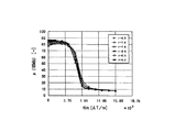
実験に用いたフェライトコアは、Mn−Zn系フェライト材で作製された磁路長7.5cm、実効断面積0.74cm2のEEコアであり、その中芯に1.5mmのギャップ加工をした。フェライトコアの中芯断面形状で、かつ高さ1.5mmの形状に加工したボンド磁石をそのギャップ部に挿入した。また、この時の直流バイアス磁界の向きは、挿入時に着磁した磁石の磁化の向きとは逆になるように重畳電流を印加する。その測定結果を図1に示す。
【0028】
図1より、y=0.03のSmCo磁石を挿入したコアについては、透磁率が高磁界側まで伸びず、磁石によるバイアス磁界の大きさが他のものに比べ非常に小さくなっていることが分かる。保磁力が7.1×79kAT/m(7.1kOe)と小さいため、大きく減磁し、重畳特性が他のものに比べ、非常に劣っていることが分かる。
【0029】
y=0.04〜0.08SmCo磁石を挿入したコアについては、直流重畳特性は高磁界側まで伸び、良好な値を示した。また、y=0.09のSmCo磁石を挿入したコアについては、透磁率が高磁界側まで伸びず、他のものに比べ特性が劣っていることが分かる。これは残留磁化が小さいためバイアス量が減少したため、直流重畳特性が劣化したものと考えられる。
【0030】
(実施例2)
実施例2による磁芯は、Sm(Fe0.2Cu0.067Zr0.028CoBal)γの遷移金属量を変化、即ちγを変化させた試料を作製し、それをSm−Coボンド磁石の特性を測定し、比較を行った例を示す。
【0031】
γの異なる試料(γ=6.5〜9.0:計7個)を高周波溶解炉で作製し、その後、焼結を1215℃で3時間、溶体化を1195℃で15時間、時効をそれぞれ800℃で40時間行って形成した。その後、金属棒で粉砕し250μm以下に分級を行った。これらのSm−Co磁石粉末に10wt%に当たる量のバインダー(エポキシ樹脂)を混合した後、無磁場中で金型成形を行い、その後、150℃で30分乾燥を行った。
【0032】
作製条件
上記の条件で作製された試料の磁気特性の結果を表2に示す。
【0034】
【表2】
表2より、γ=6.5以下では、保磁力が20×79kAT/m(20kOe)以下となり、γ=0.9では残留磁束密度が2.8T以下となり、磁気特性が劣化する。γ=7.0〜8.5の範囲では、保磁力20×79kAT/m(20kOe)以上、Brが2.8T以上で、良好な特性を示すことがわかった。
【0036】
これらのSm−Coボンド磁石をMn−Zn系フェライトコアの磁路の一部に挿入した場合の直流重畳特性を測定し、比較を行った例を示す。直流重畳特性は、各磁石を挿入したコアをHewlett Packard製4284A LCRメーターで交流磁場周波数100kHz、重畳磁場0〜15.8AT/m(200Oe)の条件で、直流重畳特性を測定した。
【0037】
実験に用いたフェライトコアは、Mn−Zn系フェライト材で作製された磁路長7.5cm、実効断面積0.74cm2のEEコアであり、その中芯に1.5mmのギャップ加工をした。フェライトコアの中芯断面形状で、かつ高さ1.5mmの形状に加工したボンド磁石をそのギャップ部に挿入した。これらの形状を図3に示す。また、この時の直流バイアス磁界の向きは、挿入時に着磁した磁石の磁化の向きとは逆になるように重畳電流を印加する。その測定結果を図2に示す。
【0038】
図2より、γ=6.5のSmCo磁石を挿入したコアについては透磁率が高磁界側まで伸びず、磁石によるバイアス磁界の大きさが他のものに比べ非常に小さくなっていることが分かる。γ=7.0〜8.5のSmCo磁石を挿入したコアについては、直流重畳特性は高磁界側まで伸び、良好な値を示した。また、γ=9.0のSmCo磁石を挿入したコアについては、透磁率が高磁界側まで伸びず、他のものに比べ特性が劣っていることが分かる。これは、残留磁化の大きさが小さいためバイアス量が減少し、直流重畳特性が劣化したものと考えられる。
【0039】
(実施例3)
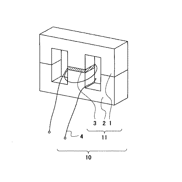
本発明の実施例3によるインダタンス部品について説明する。図3は、本発明の実施例3におけるインダクタンス部品の説明図である。図3にて、インダクタンス部品10は、E型のフェライトコア1,2と、その中心部の空隙に挿入された磁石3と、巻線4とで構成されている。ここで、磁芯11は、E型のフェライトコア1,2と磁石3との一体化して構成されたものである。このように構成することにより、直流重畳特性の良好なインダクタンス部品が提供できた。
【0040】
【発明の効果】
以上、本発明によれば、優れたコアロス特性と直流重畳特性を有する、安価な磁芯およびそれを用いたインダクタンス部品を提供できる。
【図面の簡単な説明】
【図1】本発明の実施例1における磁芯の直流重畳特性を示す図。
【図2】本発明の実施例2における磁芯の直流重畳特性を示す図。
【図3】本発明の実施例3におけるインダクタンス部品の説明図。
【符号の説明】
1,2 フェライトコア
3 磁石
4 巻線
10 インダクタンス部品
11 磁芯[0001]
TECHNICAL FIELD OF THE INVENTION
The present invention relates to a magnetic core suitable for a choke coil and a transformer magnetic core used for a switching power supply and the like, and an inductance component using the same.
[0002]
[Prior art]
Good DC superposition characteristics are required for the choke coil and transformer cores, and ferrite and dust cores are used for the high-frequency cores. Ferrite cores have characteristics derived from material properties such as high initial permeability and low saturation magnetic flux density, and dust cores have low initial magnetic permeability and high saturation magnetic flux density. Therefore, the dust core is often used in a toroidal shape, and the ferrite is often used in the EE core, for example, by inserting a gap in the middle foot of the E-type core.
[0003]
However, due to the demand for miniaturization of electronic components accompanying the recent demand for miniaturization of electronic equipment, high permeability in a large superimposed magnetic field is strongly required for inductance components. Generally, in order to improve the DC bias characteristics, it is essential to select a magnetic core having a high saturation magnetization, that is, to select a magnetic core that does not cause magnetic saturation in a high magnetic field.
However, the saturation magnetization is inevitably determined by the composition of the material, and cannot be increased infinitely. For this reason, the conventional means for improving the DC superimposition characteristic requires a great deal of labor to slightly improve the saturation magnetization. there were.
[0004]
As a solution to this problem, insertion of a gap into one or more magnetic paths and insertion of a permanent magnet into the gap have been conventionally studied. This method is an excellent method for improving DC superimposition characteristics, but when using a sintered metal magnet, the core loss of the magnetic core increases significantly, and when using a ferrite magnet, the superposition characteristics are not stable. It was not practical. As means for solving these problems, for example,
[0005]
[Patent Document 1]
Japanese Patent Application Laid-Open No. 50-133453
[Problems to be solved by the invention]
However, in recent years, the demand for improving the power conversion efficiency of power supplies has become more and more severe, and it has become difficult to determine the superiority or inferiority of cores for choke coils and transformers by simply measuring the core temperature. I have. For this reason, it is indispensable to judge the measurement result by the core loss measuring device. In fact, as a result of the study by the present inventors, it is clear that the core loss characteristic is deteriorated with the low resistivity shown in
[0007]
Therefore, we have to insert a permanent magnet having a specific coercive force of 10 × 79 kAT / m (10 kOe) or more, a Curie temperature Tc of 800 ° C. or more, and a specific resistance of 1.0 Ω · cm or more as a permanent magnet to be inserted into the gap. It has been found that good DC bias characteristics can be obtained without reducing core loss.
[0008]
However, there is a demand that exceeds these characteristic values, and in order to aim for further improvement in reliability, core loss characteristics, and superimposition characteristics, a high coercive force, a high residual magnetic flux density, and a high Curie temperature Tc of the permanent magnet inserted into the gap are required. It is necessary to develop magnets that can be combined.
[0009]
In view of the above problems, an object of the present invention is to provide an inexpensive magnetic core having excellent core loss characteristics and DC superimposition characteristics, and an inductance component using the same.
[0010]
[Means for Solving the Problems]
The present invention, as a result of examining a permanent magnet to be inserted to achieve the above-mentioned object, shows that when a permanent magnet having a specific resistance of 1.0 Ω · cm or more is used, an excellent DC superimposition characteristic is obtained, and the core loss characteristic is improved. It has been found that a magnetic core that does not deteriorate can be formed. It has been found that the magnet characteristics necessary for obtaining excellent DC superimposition characteristics are inherent coercive forces rather than energy products.
[0011]
A magnet having a high specific resistance and a high intrinsic coercive force is generally obtained by a rare earth bonded magnet formed by mixing a rare earth magnet powder with a binder. Rare earth magnet powders are classified into SmCo-based, NdFeB-based, and SmFeN-based, but in consideration of reflow conditions and oxidation resistance, the Curie temperature Tc is 800 ° C. or more, and the coercive force is 20 × 79 kAT / m (20 kOe) or more. Magnets are currently limited to Sm 2 Co 17 based magnets.
[0012]
Then, as a result of studying the Sm 2 Co 17 magnet, we found that Sm (Fe 0.15 to 0.25 Cu 0.06 to 0.08 Zr 0.02 to 0.33 Co 0.64 to 0 .77 ) Among magnets having a composition of 7.0 to 8.5 , a high-performance magnet having a Curie temperature Tc of 800 ° C. or more and a coercive force of 20 × 79 kAT / m (20 kOe) or more was found.
[0013]
BEST MODE FOR CARRYING OUT THE INVENTION
A magnetic core according to an embodiment of the present invention and an inductance component using the same will be described below.
[0014]
Any material having soft magnetic properties is effective for the core for the choke coil and the transformer, but generally, MnZn-based or Ni-Zn-based ferrite, dust core, silicon steel sheet, amorphous, etc. Is used. The shape of the magnetic core is not particularly limited, and the present invention can be applied to magnetic cores of any shape such as a toroidal core, an EE core, and an EI core. A gap is provided in at least one portion of the magnetic path of these cores, and a permanent magnet is inserted into the gap. There is no particular limitation on the gap length, but if the gap length is too narrow, the DC superposition characteristics deteriorate, and if the gap length is too wide, the magnetic permeability is too low, so the gap length to be inserted naturally is determined.
[0015]
Next, the required characteristics of the permanent magnet inserted into the gap are as follows: the specific coercive force requires a coercive force of 20 × 79 kAT / m (20 kOe) or more in order to secure reliability and suppress hysteresis loss. The larger the value, the better, but if it is 1.0 Ω · cm or more, it will not be a major factor in eddy current loss deterioration. When the average maximum particle diameter of the powder is 50 μm or more, the core loss characteristics deteriorate. Therefore, it is desirable that the maximum particle diameter of the powder be 50 μm or less, and when the minimum particle diameter is 25 μm or less, magnetization by powder oxidation during heat treatment and reflow of the powder. In order to make the reduction of remarkable, a particle size of 2.5 μm or more is required.
[0016]
A magnetic core according to an embodiment of the present invention is a magnetic core having a gap at at least one location in a magnetic path, wherein the gap has a specific coercive force of 20 × 79 kAT / m (20 kOe) or more and a Curie temperature of 300 ° C. This is a configuration in which a bonded magnet made of a resin and a rare earth magnet powder having a powder average particle diameter of 2.5 to 50 μm is inserted. Powder having a composition of Sm (Fe 0.15 to 0.25 Cu 0.06 to 0.08 Zr 0.02 to 0.03 Co 0.64 to 0.77 ) 7.0 to 8.5 in the gap. A bonded magnet made of SmCo magnet powder having an average particle size of 2.5 to 50 μm and a resin is inserted, and the bonded magnet has a resin content of 20% or more by volume and a specific resistance of 1 Ωcm or more.
[0017]
An inductance component according to an embodiment of the present invention is an inductance component including the magnetic core and at least one or more turns of the magnetic core.
[0018]
【Example】
Embodiments of the magnetic core of the present invention and an inductance component using the same will be described below.
[0019]
(Example 1)
The magnetic core according to Example 1 was prepared as follows. A sample was prepared by changing a Cu content: y of Sm (Fe 0.2 Cu y Zr 0.028 Co Bal ) 8.3 , and the sample was used as an Sm-Co bonded magnet. The following shows an example in which the characteristics were measured and compared.
[0020]
Samples with different amounts of Cu: y (y = 0.03 to 0.09: 7 in total) were prepared in a high-frequency melting furnace, followed by sintering at 1215 ° C. for 3 hours, and solution heat treatment at 1195 ° C. for 15 hours. Aging was performed at 800 ° C. for 40 hours each. Then, it was pulverized with a metal rod and classified to 250 μm or less.
[0021]
After mixing the binder (epoxy resin) in an amount corresponding to 10 wt% to these Sm-Co magnet powders, they were molded in a magnetic field-free condition, and then dried at 150 ° C. for 30 minutes to form the magnet powder.
[0022]
Manufacturing conditions
Table 1 shows the results of the magnetic properties of the samples manufactured under the above conditions.
[0024]
[Table 1]
According to Table 1, when y = 0.05 or less, the coercive force becomes 20 × 79 kAT / m (20 kOe) or less, and when y = 0.09, the residual magnetic flux density becomes 0.280 T or less, deteriorating the magnetic characteristics. It was found that in the range of y = 0.06 to 0.08, good characteristics were exhibited when the coercive force was 20 × 79 kAT / m (20 kOe) or more and Br was 0.280 T or more.
[0026]
An example in which the DC superposition characteristics of the magnetic core when these Sm-Co bonded magnets are inserted into a part of the magnetic path of the Mn-Zn-based ferrite core is measured and compared is shown. The DC superposition characteristics were measured by using a 4284A LCR meter manufactured by Hewlett Packard for the core into which each magnet was inserted, under the conditions of an AC magnetic field frequency of 100 kHz and a superposition magnetic field of 0 to 15.8 AT / m (200 Oe).
[0027]
The ferrite core used in the experiment was an EE core having a magnetic path length of 7.5 cm and an effective area of 0.74 cm 2 made of a Mn—Zn-based ferrite material, and a 1.5 mm gap was formed on the center of the core. . A bonded magnet processed into a ferrite core having a core cross-sectional shape and a height of 1.5 mm was inserted into the gap. The superimposed current is applied such that the direction of the DC bias magnetic field at this time is opposite to the direction of magnetization of the magnet magnetized at the time of insertion. FIG. 1 shows the measurement results.
[0028]
From FIG. 1, it can be seen that, for the core in which the SmCo magnet with y = 0.03 is inserted, the magnetic permeability does not extend to the high magnetic field side, and the magnitude of the bias magnetic field by the magnet is much smaller than the others. I understand. It can be seen that the coercive force is as small as 7.1 × 79 kAT / m (7.1 kOe), so that it is greatly demagnetized and the superimposition characteristics are very inferior to those of the others.
[0029]
As for the core in which y = 0.04 to 0.08 SmCo magnet was inserted, the DC superimposition characteristics extended to the high magnetic field side, and showed good values. Further, it can be seen that the magnetic permeability of the core in which the SmCo magnet with y = 0.09 is inserted does not extend to the high magnetic field side, and is inferior in characteristics to other cores. This is presumably because the amount of bias was reduced due to the small residual magnetization, and the DC bias characteristics were degraded.
[0030]
(Example 2)
The magnetic core according to Example 2 was prepared by changing a transition metal amount of Sm (Fe 0.2 Cu 0.067 Zr 0.028 Co Bal ) γ , that is, preparing a sample in which γ was changed, and then bonding it to an Sm-Co bond. An example in which characteristics of magnets are measured and compared is shown.
[0031]
Samples with different γ (γ = 6.5-9.0: 7 in total) were prepared in a high frequency melting furnace, and then sintering was performed at 1215 ° C. for 3 hours, solution heat treatment was performed at 1195 ° C. for 15 hours, and aging was performed. The film was formed at 800 ° C. for 40 hours. Then, it was pulverized with a metal rod and classified to 250 μm or less. After mixing the binder (epoxy resin) in an amount corresponding to 10 wt% to these Sm-Co magnet powders, a mold was formed in the absence of a magnetic field, and then dried at 150 ° C. for 30 minutes.
[0032]
Manufacturing conditions
Table 2 shows the results of the magnetic properties of the samples manufactured under the above conditions.
[0034]
[Table 2]
According to Table 2, when γ = 6.5 or less, the coercive force becomes 20 × 79 kAT / m (20 kOe) or less, and when γ = 0.9, the residual magnetic flux density becomes 2.8T or less, deteriorating the magnetic characteristics. In the range of γ = 7.0 to 8.5, it was found that good characteristics were exhibited when the coercive force was 20 × 79 kAT / m (20 kOe) or more and Br was 2.8 T or more.
[0036]
An example in which DC superimposition characteristics when these Sm-Co bonded magnets are inserted into a part of a magnetic path of a Mn-Zn ferrite core is measured and compared is shown. The DC superposition characteristics were measured by using a 4284A LCR meter manufactured by Hewlett Packard for the core into which each magnet was inserted, under the conditions of an AC magnetic field frequency of 100 kHz and a superposition magnetic field of 0 to 15.8 AT / m (200 Oe).
[0037]
The ferrite core used in the experiment was an EE core having a magnetic path length of 7.5 cm and an effective area of 0.74 cm 2 made of a Mn—Zn-based ferrite material, and a 1.5 mm gap was formed on the center of the core. . A bonded magnet processed into a ferrite core having a core cross-sectional shape and a height of 1.5 mm was inserted into the gap. These shapes are shown in FIG. The superimposed current is applied such that the direction of the DC bias magnetic field at this time is opposite to the direction of magnetization of the magnet magnetized at the time of insertion. FIG. 2 shows the measurement results.
[0038]
From FIG. 2, it can be seen that the magnetic permeability of the core in which the SmCo magnet with γ = 6.5 is inserted does not extend to the high magnetic field side, and the magnitude of the bias magnetic field by the magnet is much smaller than those of other cores. . With respect to the core in which the SmCo magnet with γ = 7.0 to 8.5 was inserted, the DC superimposition characteristics extended to the high magnetic field side, and showed good values. Further, it can be seen that the magnetic permeability of the core in which the SmCo magnet with γ = 9.0 is inserted does not extend to the high magnetic field side, and is inferior in characteristics to other cores. This is considered to be because the amount of bias was reduced because the magnitude of the residual magnetization was small, and the DC bias characteristics were deteriorated.
[0039]
(Example 3)
Third Embodiment An inductance component according to a third embodiment of the present invention will be described. FIG. 3 is an explanatory diagram of an inductance component according to a third embodiment of the present invention. In FIG. 3, the
[0040]
【The invention's effect】
As described above, according to the present invention, an inexpensive magnetic core having excellent core loss characteristics and DC superimposition characteristics and an inductance component using the same can be provided.
[Brief description of the drawings]
FIG. 1 is a diagram showing a DC superimposition characteristic of a magnetic core according to a first embodiment of the present invention.
FIG. 2 is a diagram illustrating a DC superposition characteristic of a magnetic core according to a second embodiment of the present invention.
FIG. 3 is an explanatory diagram of an inductance component according to a third embodiment of the present invention.
[Explanation of symbols]
1, 2
Claims (4)
Priority Applications (1)
| Application Number | Priority Date | Filing Date | Title |
|---|---|---|---|
| JP2003033901A JP2004247409A (en) | 2003-02-12 | 2003-02-12 | Magnetic core and inductance component using the same |
Applications Claiming Priority (1)
| Application Number | Priority Date | Filing Date | Title |
|---|---|---|---|
| JP2003033901A JP2004247409A (en) | 2003-02-12 | 2003-02-12 | Magnetic core and inductance component using the same |
Publications (1)
| Publication Number | Publication Date |
|---|---|
| JP2004247409A true JP2004247409A (en) | 2004-09-02 |
Family
ID=33019745
Family Applications (1)
| Application Number | Title | Priority Date | Filing Date |
|---|---|---|---|
| JP2003033901A Pending JP2004247409A (en) | 2003-02-12 | 2003-02-12 | Magnetic core and inductance component using the same |
Country Status (1)
| Country | Link |
|---|---|
| JP (1) | JP2004247409A (en) |
-
2003
- 2003-02-12 JP JP2003033901A patent/JP2004247409A/en active Pending
Similar Documents
| Publication | Publication Date | Title |
|---|---|---|
| KR100851450B1 (en) | Magnetic core with magnet for bias and inductance parts using the same | |
| KR100924037B1 (en) | Magnetic core including magnet for magnetic bias and inductor component using the same | |
| KR100851459B1 (en) | Permanent magnet, magnetic core having the magnet as bias magnet, and inductance parts using the core | |
| US6621398B2 (en) | Magnetic core comprising a bond magnet including magnetic powder whose particle's surface is coated with oxidation-resistant metal | |
| EP1211699B1 (en) | Magnetic core having magnetically biasing bond magnet and inductance part using the same | |
| JP3860456B2 (en) | Magnetic core and inductance component using the same | |
| JP3974773B2 (en) | Magnetic core having magnet for magnetic bias and inductance component using the same | |
| JP2004247409A (en) | Magnetic core and inductance component using the same | |
| JP2002231540A (en) | Magnetic core having magnet for magnetic bias and inductance part using it | |
| JP2006245418A (en) | Inductance component | |
| JP4226817B2 (en) | Magnetic core having magnetic bias magnet and inductance component using the same | |
| JP3973968B2 (en) | Magnetic core and inductance component using the same | |
| JP2003332149A (en) | Magnetic core and inductance component using the same | |
| JP2004356152A (en) | Magnetic core and inductance component using it | |
| JP2004063885A (en) | Magnetic core and inductance components using the same | |
| JP2005303020A (en) | Magnetic core having magnet for dc magnetic biasing and inductance component using the core | |
| JP2002175918A (en) | Inductor | |
| JP2005123282A (en) | Magnetic core and inductance component using it | |
| JP2002164221A (en) | Magnetic core having magnet for magnetic bias, and inductance component using the same | |
| JP2004103658A (en) | Magnetic core and inductance component using it | |
| JP2003007519A (en) | Magnetic core equipped with magnetic bias magnet and inductance part using the same | |
| JP2003257753A (en) | Magnetic core and inductance component | |
| JP2003109826A (en) | Magnetic core and inductance part | |
| JP2005019715A (en) | Magnetic core and inductance component using the same | |
| JP2005175009A (en) | Magnetic core and inductance component using the same |
Legal Events
| Date | Code | Title | Description |
|---|---|---|---|
| A621 | Written request for application examination |
Free format text: JAPANESE INTERMEDIATE CODE: A621 Effective date: 20050912 |
|
| A131 | Notification of reasons for refusal |
Free format text: JAPANESE INTERMEDIATE CODE: A131 Effective date: 20070704 |
|
| A02 | Decision of refusal |
Free format text: JAPANESE INTERMEDIATE CODE: A02 Effective date: 20071205 |