EP1202099A2 - Electrostatic actuator and camera module using the same - Google Patents
Electrostatic actuator and camera module using the same Download PDFInfo
- Publication number
- EP1202099A2 EP1202099A2 EP01309277A EP01309277A EP1202099A2 EP 1202099 A2 EP1202099 A2 EP 1202099A2 EP 01309277 A EP01309277 A EP 01309277A EP 01309277 A EP01309277 A EP 01309277A EP 1202099 A2 EP1202099 A2 EP 1202099A2
- Authority
- EP
- European Patent Office
- Prior art keywords
- electrode
- electrodes
- section
- period
- movable section
- Prior art date
- Legal status (The legal status is an assumption and is not a legal conclusion. Google has not performed a legal analysis and makes no representation as to the accuracy of the status listed.)
- Withdrawn
Links
Images








Classifications
-
- G—PHYSICS
- G02—OPTICS
- G02B—OPTICAL ELEMENTS, SYSTEMS OR APPARATUS
- G02B7/00—Mountings, adjusting means, or light-tight connections, for optical elements
- G02B7/02—Mountings, adjusting means, or light-tight connections, for optical elements for lenses
- G02B7/04—Mountings, adjusting means, or light-tight connections, for optical elements for lenses with mechanism for focusing or varying magnification
- G02B7/08—Mountings, adjusting means, or light-tight connections, for optical elements for lenses with mechanism for focusing or varying magnification adapted to co-operate with a remote control mechanism
-
- H—ELECTRICITY
- H02—GENERATION; CONVERSION OR DISTRIBUTION OF ELECTRIC POWER
- H02N—ELECTRIC MACHINES NOT OTHERWISE PROVIDED FOR
- H02N1/00—Electrostatic generators or motors using a solid moving electrostatic charge carrier
- H02N1/002—Electrostatic motors
- H02N1/004—Electrostatic motors in which a body is moved along a path due to interaction with an electric field travelling along the path
Definitions
- the movable section is macroscopically moved successively in the longitudinal direction of the stator sections by 1/2 pitch of the electrode array while being vibrated microscopically between the first stator section and the second stator section.
- the moving direction of the movable section can be changed by changing the order of applying a DV voltage to the electrodes of groups A, B, C and D.
- the movable section can be moved in a first direction by applying a DC voltage to the electrodes of groups A and B, the electrodes of groups B and C, the electrodes of groups C and D, and the electrodes of group D in the order mentioned.
- an electrostatic actuator comprising:
- an electrostatic actuator comprising:
- an electrostatic actuator comprising:
- an electrostatic actuator comprising:
- a camera module for photographing a picture image comprising:
- a camera module for photographing a picture image comprising:
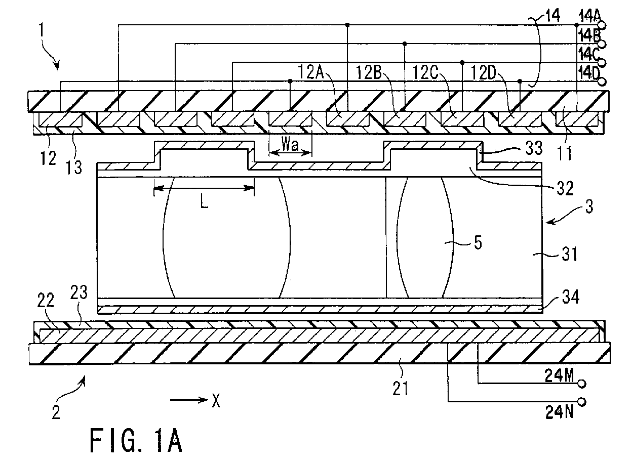
- the first, second, third and fourth electrodes are called the electrodes 12A, 12B, 12C and 12D, and the capital letters A, B, C, D are put in the drawing to the wirings to these first to fourth electrodes, respectively, so as to clarify the connecting relationship.
- the first electrodes 12A are commonly connected by a wiring 14A so as to be connected to the driving circuit 4.
- the second electrodes 12B are commonly connected by the wiring 14B so as to be connected to the driving circuit 4
- the third electrodes 12C are commonly connected by the wiring 14C so as to be connected to the driving circuit 4.
- the fourth electrodes 12D are commonly connected by the wiring 14D so as to be connected to the driving circuit 4.
- the wiring 14 is of a two layer structure having an insulating layer interposed between the upper and lower conductive layers. In other words, the wiring 14 is of a steric wiring structure constructed such that one end of each of the upper and lower conductive layers is connected to the driving circuit 4.
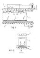
- the second stator section 2 includes an insulating substrate 21, a second electrode array 22 formed on the insulating substrate 21, and a dielectric film 23 formed to cover the upper surface of the second electrode array 22.
- the second electrode array 22 includes two band-like electrodes 22M and 22N formed to extend in the longitudinal direction of the substrate 21 (first direction or the X-direction) apart from each other in the second direction (Y-direction) perpendicular to the X-direction. These electrodes 22M and 22N are connected to the driving circuit 4.
- the moving operation of the movable section is rendered unstable under the influence of the dielectric polarization of the dielectric film.
- the voltage application pattern to the electrodes is improved so as to overcome the problem pointed out above as described in detail herein later.
- the movable section 3 is formed of a hollow parallelepiped insulating substrate 31.
- the insulating substrate 31 includes a convex portion 32 on the side facing the first electrode array 12 on the first stator section 1.
- the fifth electrode 33 is mounted to the surface of the convex portion 32 facing the first electrode array 12, and the sixth electrode 34 is mounted to the surface of the convex portion 32 facing the second electrode array 22 on the second stator section 2.
- the movable section 3 is arranged movable in the right-left direction (X-direction) in the moving space between the first stator section 1 and the second stator section 2. As shown in FIG.
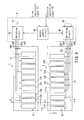
- the output generated from the output terminal is controlled by a control signal generated from the switch control circuit and supplied to the input terminal.
- the switch control circuit 45 is constructed to control the switching circuits 43, 44 in accordance with a drive instruction signal S1 and a direction instruction signal S2 generated from, for example, a host computer (not shown).
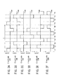
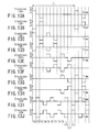
- a positive voltage and a negative voltage are applied to the electrode 12B and the electrode 12C, respectively, during a period T3 as shown in FIGS. 3B and 3C.
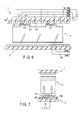
- line E3 of electric force is generated to run through the electrode 12B, the fifth electrode 33 and the electrode 12C, and an electrostatic attractive force is generated between the electrodes 12B, 12C and the fifth electrode 33.
- the movable section 3 is moved toward the first stator section 1.
- the electrodes 12B, 12C included in the first electrode array 12 and having voltages applied thereto are deviated by one pitch (P) from the electrodes 12A, 12B to which the voltages were applied previously during the period T1. It follows that the movable section 3 is moved to the right by one pitch P when moved toward the first stator section 2.
- second electrodes 22F are commonly connected by the wiring 24F so as to be connected to the driving circuit 4
- third electrodes 22G are commonly connected by the wiring 24G so as to be connected to the driving circuit 4.
- fourth electrodes 22H are commonly connected by the wiring 24H so as to be connected to the driving circuit 4.
- the wiring 24 is of a two layer structure having an insulating layer interposed between the upper and lower conductive layers. In other words, the wiring 24 is of a steric wiring structure constructed such that one end of each of the upper and lower conductive layers is connected to the driving circuit 4.
- FIG. 14 is a plan view showing the first electrode array 12 of the first stator section 1 included in the electrostatic actuator according to a fourth embodiment of the present invention.
- the first electrode array 12 includes a first electrode group 12-1 consisting of the electrodes 12A+ and 12B+, a second electrode group 12-2 consisting of the electrodes 12A- and 12B-, a third electrode group 12-3 consisting of the electrodes 12C+ and 12D+ and a fourth electrode group 12-4 consisting of the electrodes 12C-and 12D-.
- These electrode groups 12-1, 12-4, 12-3 and 12-2 are arranged in the order mentioned.
- the second electrode array 22 on the second stator section 2 consists of two band-like electrodes 22M and 22N formed on the substrate 21 a predetermined distance apart from each other and extending in the longitudinal direction (X-direction) of the substrate 21. Further, the fifth electrode 33 is formed in four rows on the movable section 3 in a manner to correspond to the electrode groups 12-1, 12-2, 12-3, 12-4 of the first electrode array 12.
- connection between the electrode and the pad can be achieved by a planar wiring in place of a steric wiring so as to improve the mass production capability of the electrostatic actuator.
- the first electrode array 12 in the fifth embodiment includes a first electrode group 12-1 consisting of the electrodes 12A+ and 12B+, a second electrode group 12-2 consisting of the electrodes 12A- and 12B-, a third electrode group 12-3 consisting of the electrodes 12C+ and 12D+, a fourth electrode group 12-4 consisting of the electrodes 12C- and 12D-, a fifth electrode group 12-5 consisting of the electrodes 12E+ and 12F+, and a sixth electrode group 12-6 consisting of the electrodes 12E-and 12F-,.
- These electrode groups 12-1, 12-2, 12-3, 12-4, 12-5 and 12-6 are arranged in the order mentioned.
- a positive voltage is applied to the electrode 12F+ and a negative voltage is applied to the electrode 12F- for a predetermined period so as to generate an electrostatic attractive force between the electrodes 12C+, 12C- and the fifth electrode 33, with the result that the movable section 3 is moved toward the first stator section 1.
- a negative voltage is applied to the electrode 22M and a positive voltage is applied to the electrode 22N so as to generate an electrostatic attractive force between the electrodes 22M, 22N and the sixth electrode 34, with the result that the movable section 3 is moved toward the second stator section 2.
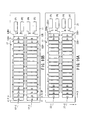
- FIGS. 12A and 12B show the first electrode array 12 on the first stator section 1 and the second electrode array 22 on the second stator section 22, respectively, according to a sixth embodiment of the present invention.
- the first electrode array 12 includes a first electrode group 12-1 consisting of electrodes 12A+ and 12B+ each arranged at a pitch P in a manner to extend in the X-direction and a second electrode group 12-2 consisting of electrodes 12A- and 12B- each arranged at a pitch P in a manner to extend in the X-direction.
- the electrodes 12A+, the electrodes 12B+, the electrodes 12A- and the electrodes 12B- are commonly connected to the driving circuit (not shown) through the pads P1, P2, P3 and P4, respectivelsy.
- the electrode 12C+, the electrode 12D+, the electrode 12C- and the electrode 12D- belong to the groups of the electrode 12C+, the electrode 12D+, the electrode 12C-and the electrode 12D-, respectively, and are commonly connected for each group to the driving circuit (not shown) through the pads P5, P6, P7 and P8.
- the circuit consisting of the electrode 12C+, the sixth electrode 34 and the electrode 12C- equivalently corresponds to a series circuit including two capacitors so as to generate lines of electric force running through the electrode 12C+, the sixth electrode 34 and the electrode 12C-. Since the lines of electric force thus generated tend to shrink as much as possible, an electrostatic attractive force is generated between the electrodes 12C+, 12C- and the fifth electrode 33, with the result that the movable section 3 is moved toward the second stator section 2.
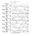
- a positive voltage is applied to the electrode 12D+ on the second stator section 2 and a negative voltage is applied to the electrode 12D- on the second stator section 2 during a period T4 as shown in FIGS. 17G and 17H.
- lines of electric force are generated to run through the electrode 12D+, the sixth electrode 34 and the electrode 12D-, and an electrostatic attractive force is generated between the electrodes 12D+, 12D- and the sixth electrode 34, with the result that the movable section 3 is moved toward the second stator section 2.
- a DC voltage is applied successively to the electrode 12A+, the electrode 12A-, the electrode 12B+, the electrode 12B-, the electrode 12C+, the electrode 12C-, the electrode 12D+ and the electrode 12D- during periods T4 to T8, and the driving operation of one period T is finished by the periods T1 to T8.
- the polarity of the DC voltage applied during the periods T5 to T8 is opposite to that of the DC voltage applied during the periods T1 to T4, as apparent from FIGS. 17A to 17H, with the result that the charge produced by the dielectric polarization of the dielectric films 13, 23 is canceled as in the embodiments described previously. It follows that the moving operation of the movable section 3 is prevented from being rendered unstable by the dielectric polarization.
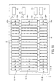
- FIG. 19 is a plan view showing the first electrode array 12 on the first stator section 1 according to a eighth embodiment of the present invention.
- the eighth embodiment differs from the sixth embodiment in that the electrode 12B+ in the sixth embodiment is divided in the second direction (Y-direction) into three electrodes, and the divided electrodes 12B- are arranged between the adjacent electrodes 12A+. These divided electrodes 12B- are commonly connected by a wiring and collectively perform the function of a single electrode group.
- the phase of the electrodes of the second electrode array (not shown) on the second stator section 2 is deviated by 1/2 pitch from the phase of the electrodes of the first electrode array as in the sixth embodiment.
- the driving operation of the eighth embodiment is equal to that of the sixth embodiment and, thus, the description is omitted in respect of the driving operation of the eighth embodiment.
- FIG. 20 is a plan view showing the construction of the second electrode array 22 on the second stator section 2 according to an ninth embodiment of the present invention.
- the second electrode array 22 includes the electrodes 22M and 22N as in the first embodiment. What should be noted is that each of these electrodes 22M and 22N is in the shape of comb teeth, and the teeth of these electrodes 22M and 22N are meshed with each other in a con-contact fashion.
- the second electrode array 22 of the particular construction produces the effect similar to that produced by the second electrode array 22 used in the first embodiment.
- FIG. 21 shows the module portion of a small electronic camera using the electrostatic actuator according to the ninth embodiment of the present invention in the focus adjusting mechanism.
- a solid state image pick-up element 101 formed of a CMOS or a CCD is arranged on a substrate 100, and an electrostatic actuator 102 is mounted to the solid state image pick-up element 101.
- a lens 5 is integrally mounted to the movable section 3 as shown in FIG. 1.
- the driving circuit 4 of the electrostatic actuator 102 and an IC chip 103 including, for example, a DSP (digital signal processor) chip for controlling the driving circuit 4 are mounted to the substrate 100.
- DSP digital signal processor
- the electronic camera module can be formed very small as shown in FIG. 21 and is adapted for use in, for example, a portable telephone and a digital camera.
Landscapes
- Physics & Mathematics (AREA)
- General Physics & Mathematics (AREA)
- Optics & Photonics (AREA)
- Studio Devices (AREA)
- Micromachines (AREA)
- General Electrical Machinery Utilizing Piezoelectricity, Electrostriction Or Magnetostriction (AREA)
Abstract
Description
Claims (19)
- An electrostatic actuator, characterized by comprising:a first stator section (1) including a first electrode array (12) including first, second and third electrodes (12A, 12B, 12C, 12D) arranged at a predetermined pitch in a first direction;a second stator section (2) arranged to face the first stator section (1) and to define a space between the first and second stator sections (1, 2), and including a second electrode array (22) including fourth and fifth electrodes (22M, 22N) extending in the first direction;a movable section (3) arranged in the space and including a first electrode section (33) facing the first electrode array (12) and a second electrode section (34) facing the second electrode array (22), the first and second electrode sections (33, 34) being maintained at a predetermined floating potential; anda driving circuit (4) configured to apply DC voltage signals to the first and second electrode arrays (12, 22), alternatively, the DC voltage signal having a first level higher than the predetermined floating potential and a second level lower than the predetermined floating potential,the first DC voltage signal being applied to the adjacent first and second electrodes (12A, 12B, 12C, 12D) of the first electrode array (12) to attract the first electrode section (33) of the movable section (3) during a first period, the first and second electrodes (12A, 12B, 12C, 12D) of the first electrode array (12) being maintained at the first and second levels during the first period, respectively,the second DC voltage signal being applied to the fourth and fifth electrodes (22, 22M, 22N, 22E, 22F, 22G, 22H) of the second electrode array (22) to attract the second electrode section (34) of the movable section (3) during a second period, the fourth and fifth electrodes (22, 22M, 22N, 22E, 22F, 22G, 22H) of the second electrode array (22) being maintained at the first and second levels during the second period, respectively,the third DC voltage signal being applied to the adjacent second and third electrodes (12A, 12B, 12C, 12D) of the first electrode array (12) to attract the first electrode section (33) of the movable section (3) during a third period, the second and third electrodes (12A, 12B, 12C, 12D) of the first electrode array (12) being maintained at the first and second levels during the third period, respectively,the fourth DC voltage signal being applied to the fourth and fifth electrodes (22, 22M, 22N, 22E, 22F, 22G, 22H) of the second electrode array (22) to attract the second electrode section (34) of the movable section (3) during a fourth period, the fourth electrode (22, 22M, 22N, 22E, 22F, 22G, 22H) of the second electrode array (22) being maintained at one of the first and second levels during the fourth period, and the fifth electrode (22, 22M, 22N, 22E, 22F, 22G, 22H) of the second electrode array (22) being maintained at the other of first and second levels during the fourth period, andthe movable section (3) being moved in the first direction in accordance with the application of the first, second, third and fourth DC voltage signals.
- The electrostatic actuator according to claim 1, characterized in that:the first electrode array (12) further includes a sixth electrode,the fifth DC voltage signal being applied to the adjacent third and sixth electrodes (12A, 12B, 12C, 12D) of the first electrode array (12) to attract the first electrode section'(33) of the movable section (3) during a fifth period, the third and sixth electrodes (12A, 12B, 12C, 12D) of the first electrode array (12) being maintained at the first and second levels during the fifth period, respectively.
- The electrostatic actuator according to either of claims 1 or 2, characterized in that:the movable section (3) has concave and convex portions faced to the first electrode array (12), the first electrode section (33) of the movable section (3) formed on the convex portion.
- An electrostatic actuator, characterized by comprising:a first stator section (1) including a first electrode array (12) including first, second and third electrodes (12A, 12B, 12C, 12D) arranged at a predetermined pitch in a first direction;a second stator section (2) arranged to face the first stator section (1) and to define a space between the first and second stator sections (1, 2), and including a second electrode array (22) including fourth, fifth and sixth electrodes (22E, 22F, 22G, 22H) arranged at the predetermined pitch in the first direction;a movable section (3) arranged in the space and including a first electrode section (33) facing the first electrode array (12) and a second electrode section (34) facing the second electrode array (22), the first and second electrode sections (33, 34) being maintained at a predetermined floating potential; anda driving circuit (4) configured to apply DC voltage signals to the first and second electrode arrays (12, 22), alternatively, the DC voltage signal having a first level higher than the predetermined floating potential and a second level lower than the predetermined floating potential,the first DC voltage signal being applied to the adjacent first and second electrodes (12A, 12B, 12C, 12D) of the first electrode array (12) to attract the first electrode section (33) of the movable section (3) during a first period, the first and second electrodes (12A, 12B, 12C, 12D) of the first electrode array (12) being maintained at the first and second levels during the first period, respectively,the second DC voltage signal being applied to the adjacent fourth and fifth electrodes (22E, 22F, 22G, 22H) of the second electrode array (22) to attract the second electrode section (34) of the movable section (3) during a second period, the fourth and fifth electrodes (22E, 22F, 22G, 22H) of the second electrode array (22) being maintained at the first and second levels during the second period, respectively,the third DC voltage signal being applied to the adjacent second and third electrodes (12A, 12B, 12C, 12D) of the first electrode array (12) to attract the first electrode section (33) of the movable section (3) during a third period, the second and third electrodes (12A, 12B, 12C, 12D) of the first electrode array (12) being maintained at the first and second levels during the third period, respectively,the fourth DC voltage signal being applied to the adjacent fifth and sixth electrodes (22E, 22F, 22G, 22H) of the second electrode array (22) to attract the second electrode section (34) of the movable section (3) during a fourth period, the fifth and sixth electrodes (22E, 22F, 22G, 22H) of the second electrode array (22) being maintained at the first and second levels during the fourth period, respectively, andthe movable section (3) being moved in the first direction in accordance with the application of the first, second, third and fourth DC voltage signals.
- The electrostatic actuator according to claim 4, characterized in that:the second electrode array (22) is arranged at the same pitch as that of the first electrode array (12) in the first direction and the arrangement of the second electrode array (22) is deviated by half the predetermined pitch from the arrangement of the first electrode array (12).
- The electrostatic actuator according to claim 4, characterized in that:the first electrode array (12) further includes a seventh electrode (12A, 12B, 12C, 12D),the second electrode array (22) further includes a eighth electrode (22E, 22F, 22G, 22H),the fifth DC voltage signal is applied to the adjacent third and seventh electrodes (12A, 12B, 12C, 12D) of the first electrode array (12) to attract the first electrode section (33) of the movable section (3) during a fifth period, the third and seventh electrodes (12A, 12B, 12C, 12D) of the first electrode array (12) being maintained at the first and second levels during the fifth period, respectively andthe sixth DC voltage signal is applied to the fourth and eighth electrodes (22E, 22F, 22G, 22H) of the second electrode array (22) to attract the second electrode section (34) of the movable section (3) during a sixth period, the fourth and eighth electrodes (22E, 22F, 22G, 22H) of the second electrode array (22) being maintained at the first and second levels during the sixth period, respectively.
- The electrostatic actuator according to any of claims 4 to 6, characterized in that:the movable section (3) has concave and convex portions faced to the first electrode array (12), the first electrode section (33) of the movable section (3) formed on the convex portion.
- An electrostatic actuator, characterized by comprising:a first stator section (1) including first and second electrode arrays (12, 12-1, 12-2) each including first, second and third electrodes (12A+, 12B+, 12C+, 12D+, 12A-, 12B-, 12C-, 12D-) and arranged substantially in parallel and at a predetermined pitch in a first direction;a second stator section (2) arranged to face the first stator section (1) and to define a space between the first and second stator sections (1, 2), and including a third electrode array (22) including fourth and fifth electrodes (22M, 22N);a movable section (3) arranged in the space and including a first electrode section (33) facing the first electrode array (12) and a second electrode section (34) facing the second electrode array (22), the first and second electrode sections (33, 34) being maintained at a predetermined floating potential; anda driving circuit (4) configured to apply DC voltage signals to the first, second and third electrode arrays (12, 12-1, 12-2) and the third electrode array (22), alternatively, the DC voltage signal having a first level higher than the predetermined floating potential and a second level lower than the predetermined floating potential,the first DC voltage signal being applied to the first and second electrodes (12A+, 12B+, 12C+, 12D+, 12A-, 12B-, 12C-, 12D-) of the first and second electrode arrays (12, 12-1, 12-2) to attract the first electrode section (33) of the movable section (3) during a first period, the first electrodes (12A+, 12B+, 12C+, 12D+, 12A-, 12B-, 12C-, 12D-) of the first and second electrode arrays (12, 12-1, 12-2) being maintained at the first and second levels during the first period, respectively,the second DC voltage signal being applied to the fourth and fifth electrodes (22M, 22N) of the third electrode array (22) to attract the second electrode section (34) of the movable section (3) during a second period,the third DC voltage signal being applied to the second and third electrodes (12A+, 12B+, 12C+, 12D+, 12A-, 12B-, 12C-, 12D-) of the first and second electrode arrays (12, 12-1, 12-2) to attract the first electrode section (33) of the movable section (3) during a third period, the second and third electrodes (12A+, 12B+, 12C+, 12D+, 12A-, 12B-, 12C-, 12D-) of the first and second electrode arrays (12, 12-1, 12-2) being maintained at the first and second levels during the third period, respectively, and the movable section (3) being moved in the first direction in accordance with the application of the first, second and third DC voltage signals.
- The electrostatic actuator according to claim 8, characterized in that:the first and second electrodes (22M, 22N) of the third electrode array (22) are extended in the first direction.
- The electrostatic actuator according to claim 9, characterized in that:the first and second electrode arrays (12, 12-1, 12-2) further includes sixth electrodes (12A+, 12B+, 12C+, 12D+, 12A-, 12B-, 12C-, 12D-),the fourth DC voltage signal is applied to the fourth and fifth electrodes (22M, 22N) of the third electrode array (22) to attract the second electrode section (34) of the movable section (3) during a fourth period, andthe fifth DC voltage signal is applied to the sixth electrodes (12A+, 12B+, 12C+, 12D+, 12A-, 12B-, 12C-, 12D-) of the first and second electrode arrays (12, 12-1, 12-2) to attract the second electrode section (34) of the movable section (3) during a fifth period.
- An electrostatic actuator, characterized by comprising:a first stator section (1) including first and second electrode arrays (12, 12-1, 12-2) each including first and second electrodes (12A+, 12B+, 12A-, 12B-) and arranged substantially in parallel and at a predetermined pitch in a first direction;a second stator section (2) arranged to face the first stator section (1) and to define a space between the first and second stator sections (1, 2), and including third and fourth electrode arrays (22, 22-1, 22-2) each including third and fourth electrodes (22C+, 22D+,22C-, 22D-) and arranged substantially in parallel and at a predetermined pitch in the first direction, the third and fourth electrode array (22, 22-1, 22-2) being arranged at the same pitch as that of the first and second electrode arrays (12, 12-1, 12-2) in the first direction and the arrangement of the third and fourth electrode arrays (22, 22-1, 22-2) being deviated by the half of the predetermined pitch from the arrangement of the first and second electrode arrays (12, 12-1, 12-2);a movable section (3) arranged in the space and including a first electrode section (33) facing the first and second electrode arrays (12, 12-1, 12-2) and a second electrode section (34) facing the third and fourth electrode arrays (22, 22-1, 22-2), the first and second electrode sections (33, 34) being maintained at a predetermined floating potential; anda driving circuit (4) configured to apply DC voltage signals to the first, second, third and fourth electrode arrays(12, 12-1, 12-2, 22, 22-1, 22-2), alternatively, the DC voltage signal having a first level higher than the predetermined floating potential and a second level lower than the predetermined floating potential,the first DC voltage being applied to the first electrodes (12A+, 12B+, 12A-, 12B-) of the first and second electrode arrays (12, 12-1, 12-2) to attract the first electrode section (33) of the movable section (3) during a first period, the first electrodes (12A+, 12B+, 12A-, 12B-) of the first and second electrode arrays (12, 12-1, 12-2) being maintained at the first and second levels during the first period, respectively,the second DC voltage being applied to the third electrodes (22C+, 22D+,22C-, 22D-) of the third and fourth electrode arrays (22, 22-1, 22-2) to attract the second electrode section (34) of the movable section (3) during a second period, the third electrodes of the third and fourth electrode arrays being maintained at the first and second levels during the second period, respectively,the third DC voltage being applied to the second electrodes (12A+, 12B+, 12A-, 12B-) of the first and second electrode arrays (12, 12-1, 12-2) to attract the first electrode section (33) of the movable section (3) during a third period, the second electrodes (12A+, 12B+, 12A-, 12B-) of the first and second electrode arrays (12, 12-1, 12-2) being maintained at the first and second levels during the third period, respectively,the fourth DC voltage being applied to the fourth electrodes (22C+, 22D+,22C-, 22D-) of the third and fourth electrode arrays (22, 22-1, 22-2) to attract the second electrode section (34) of the movable section (3) during a fourth period, the fourth electrodes (22C+, 22D+,22C-, 22D-) of the third and fourth electrode arrays (22, 22-1, 22-2) being maintained at the third and fourth levels during the fourth period, respectively, andthe movable section (3) being moved in the first direction in accordance with the application of the first, second, third and fourth DC voltage signals.
- The electrostatic actuator according to claim 11, characterized in that:the first and second electrode arrays (12, 12-1, 12-2) further includes a fifth electrode (12A+, 12B+, 12A-, 12B-),the third and fourth electrode arrays (22, 22-1, 22-2) further includes a sixth electrode (22C+, 22D+,22C-, 22D-),the fifth DC voltage signal is applied to the fifth electrodes (12A+, 12B+, 12A-, 12B-) of the first and second electrode arrays (12, 12-1, 12-2) to attract the first electrode section (33) of the movable section (3) during a fifth period, the fifth electrodes (12A+, 12B+, 12A-, 12B-) of the first and second electrode arrays (12, 12-1, 12-2) being maintained at the first and second levels during the fifth period, respectively andthe sixth DC voltage signal is applied to the sixth electrodes (22C+, 22D+,22C-, 22D-) of the third and fourth electrode arrays (22, 22-1, 22-2) to attract the second electrode section (34) of the movable section (3) during a sixth period, the sixth electrodes (22C+, 22D+,22C-, 22D-) of the third and fourth electrode arrays (22, 22-1, 22-2) being maintained at the first and second levels during the sixth period, respectively.
- An electrostatic actuator, characterized by comprising:a first stator section (1) including first, second and third electrode arrays (12, 12-1, 12-2, 12-3) each including first and second electrodes (12A+, 12A-, 12B+, 12B-) and arranged substantially in parallel and at a predetermined pitch in a first direction;a second stator section (2) arranged to face the first stator section (1) and to define a space between the first and second stator sections (1, 2), and including a fourth electrode array (22) including fourth and fifth electrodes (22M, 22N);a movable section (3) arranged in the space and including a first electrode section (33) facing the first, second and third electrode arrays (12) and a second electrode section (34) facing the fourth electrode array (22), the first and second electrode sections (33, 34) being maintained at a predetermined floating potential; anda driving circuit (4) configured to apply DC voltage signals to the first, second, third and fourth electrode arrays (12, 12-1, 12-2, 12-3, 22), alternatively, the DC voltage signal having a first level higher than the predetermined floating potential and a second level lower than the predetermined floating potential,the first DC voltage signal being applied to the first and second electrodes (12A+, 12A-, 12B+, 12B-) of the first, second and third electrode arrays (12, 12-1, 12-2, 12-3) to attract the first electrode section (33) of the movable section (3) during a first period, the first and second electrodes (12A+, 12A-, 12B+, 12B-) of the first and third electrode arrays (12, 12-1, 12-2, 12-3) being maintained at one of the first and second levels during the first period and the first and second electrodes (12A+, 12A-, 12B+, 12B-) of the second electrode array (12, 12-2) being maintained at the other of the first and second levels during the first period,the second DC voltage signal being applied to the third and fourth electrodes (22M, 22N) of the fourth electrode array (22) to attract the second electrode section (34) of the movable section (3) during a second period,the third DC voltage signal being applied to the second and third electrodes (12A+, 12A-, 12B+, 12B-) of the first, second and third electrode arrays (12, 12-1, 12-2, 12-3) to attract the first electrode section (33) of the movable section (3) during a third period, the second and third electrodes (12A+, 12A-, 12B+, 12B-) of the first and third electrode arrays (12, 12-1, 12-2, 12-3) being maintained at one of the first and second levels during the third period, the second electrodes (12A+, 12A-, 12B+, 12B-) of the second electrode array (12, 12-2) being maintained at the other of the first and second levels during the third period, and the movable section (3) being moved in the first direction in accordance with the application of the first, second and third DC voltage signals.
- The electrostatic actuator according to claim 13, characterized in that:the first and second electrodes (22M, 22N) of the fourth electrode array (22) are extended in the first direction.
- The electrostatic actuator according to claim 14, characterized in that:the movable section (3) has concave and convex portions faced to the first electrode array (12), the first electrode section (33) of the movable section (3) formed on the convex portion.
- A camera module for photographing a picture image, characterized by comprising:an electrostatic actuator, including:a first stator section (1) including a first electrode array (12) including first, second and third electrodes (12A, 12B, 12C, 12D) arranged at a predetermined pitch in a first direction;a second stator section (2) arranged to face the first stator section (1) and to define a space between the first and second stator sections (1, 2), and including a second electrode array (22) including fourth and fifth electrodes (22, 22M, 22N, 22E, 22F, 22G, 22H);a movable section (3) arranged in the space and including a first electrode section (33) facing the first electrode array (12) and a second electrode section (34) facing the second electrode array (22), the first and second electrode sections (33, 34) of the movable section (3) being maintained at a predetermined floating potential; anda driving circuit (4) configured to apply DC voltage signals to the first and second electrode arrays (12, 22), alternatively, the DC voltage signal having a first level higher than the predetermined floating potential and a second level lower than the predetermined floating potential,the first DC voltage signal being applied to the adjacent first and second electrodes of the first electrode array (12) to attract the first electrode section (33) of the movable section (3) during a first period, the first and second electrodes of the first electrode array (12) being maintained at the first and second levels during the first period, respectively,the second DC voltage signal being applied to the fourth and fifth electrodes of the second electrode array (22) to attract the second electrode section (34) of the movable section (3) during a second period,the third DC voltage signal being applied to the adjacent second and third electrodes of the first electrode array (12) to attract the first electrode section (33) of the movable section (3) during a third period, the second and third electrodes of the first electrode array (12) being maintained at the first and second levels during the third period, respectively, and the movable section (3) being moved in the first direction in accordance with the application of the first, second and third voltage signals.a lens (5) mounted in the movable section (3) and movable with the movable section (3), configured to transfer the picture image; andan image pick-up element (101) configured to receive the transferred picture image to generate a image signal.
- A camera module for photographing a picture image, characterized by comprising:an electrostatic actuator, including:a first stator section (1) including a first electrode array (12) including first, second and third electrodes (12A, 12B, 12C, 12D) arranged at a predetermined pitch in a first direction;a second stator section (2) arranged to face the first stator section (1) and to define a space between the first and second stator sections (1, 2), and including a second electrode array (22) including fourth, fifth and sixth electrodes (22E, 22F, 22G, 22H) arranged at the predetermined pitch in the first direction;a movable section (3) arranged in the space and including a first electrode section (33) facing the first electrode array (12) and a second electrode section (34) facing the second electrode array (22), the first and second electrode sections (33, 34) being maintained at a predetermined floating potential; anda driving circuit (4) configured to apply DC voltage signals to the first and second electrode arrays (12, 22), alternatively, the DC voltage signal having a first level higher than the predetermined floating potential and a second level lower than the predetermined floating potential,the first DC voltage signal being applied to the adjacent first and second electrodes (12A, 12B, 12C, 12D) of the first electrode array (12) to attract the first electrode section (33) of the movable section (3) during a first period, the first and second electrodes (12A, 12B, 12C, 12D) of the first electrode array (12) being maintained at the first and second levels during the first period, respectively,the second DC voltage signal being applied to the adjacent fourth and fifth electrodes (22E, 22F, 22G, 22H) of the second electrode array (22) to attract the second electrode section (34) of the movable section (3) during a second period, the fourth and fifth electrodes (22E, 22F, 22G, 22H) of the second electrode array (22) being maintained at the first and second levels during the second period, respectively,the third DC voltage signal being applied to the adjacent second and third electrodes (12A, 12B, 12C, 12D) of the first electrode array (12) to attract the first electrode section (33) of the movable section (3) during a third period, the second and third electrodes (12A, 12B, 12C, 12D) of the first electrode array (12) being maintained at the first and second levels during the third period, respectively,the fourth DC voltage signal being applied to the adjacent fifth and sixth electrodes (22E, 22F, 22G, 22H) of the second electrode array (22) to attract the second electrode section (34) of the movable section (3) during a fourth period, the fifth and sixth electrodes (22E, 22F, 22G, 22H) of the second electrode array (22) being maintained at the first and second levels during the fourth period, respectively, andthe movable section (3) being moved in the first direction in accordance with the application of the first, second, third and fourth DC voltage signals.a lens (5) mounted in the movable section (3) and movable with the movable section (3), configured to transfer the picture image; andan image pick-up element (101) configured to receive the transferred picture image to generate a image signal.
- A camera module for photographing a picture image, characterized by comprising:an electrostatic actuator, including:a first stator section (1) including first and second electrode arrays (12, 12-1, 12-2) each including first and second electrodes (12A+, 12B+, 12A-, 12B-) and arranged substantially in parallel and at a predetermined pitch in a first direction;a second stator section (2) arranged to face the first stator section (1) and to define a space between the first and second stator sections (1, 2), and including third and fourth electrode arrays (22, 22-1, 22-2) each including third and fourth electrodes (22C+, 22D+,22C-, 22D-) and arranged substantially in parallel and at a predetermined pitch in the first direction, the third and fourth electrode array (22, 22-1, 22-2) being arranged at the same pitch as that of the first and second electrode arrays (12, 12-1, 12-2) in the first direction and the arrangement of the third and fourth electrode arrays (22, 22-1, 22-2) being deviated by the half of the predetermined pitch from the arrangement of the first and second electrode arrays (12, 12-1, 12-2);a movable section (3) arranged in the space and including a first electrode section (33) facing the first and second electrode arrays (12, 12-1, 12-2) and a second electrode section (34) facing the third and fourth electrode arrays (22, 22-1, 22-2), the first and second electrode sections (33, 34) being maintained at a predetermined floating potential; anda driving circuit (4) configured to apply DC voltage signals to the first, second, third and fourth electrode arrays(12, 12-1, 12-2, 22, 22-1, 22-2), alternatively, the DC voltage signal having a first level higher than the predetermined floating potential and a second level lower than the predetermined floating potential,the first DC voltage being applied to the first electrodes (12A+, 12B+, 12A-, 12B-) of the first and second electrode arrays (12, 12-1, 12-2) to attract the first electrode section (33) of the movable section (3) during a first period, the first electrodes (12A+, 12B+, 12A-, 12B-) of the first and second electrode arrays (12, 12-1, 12-2) being maintained at the first and second levels during the first period, respectively,the second DC voltage being applied to the third electrodes (22C+, 22D+,22C-, 22D-) of the third and fourth electrode arrays (22, 22-1, 22-2) to attract the second electrode section (34) of the movable section (3) during a second period, the third electrodes of the third and fourth electrode arrays being maintained at the first and second levels during the second period, respectively,the third DC voltage being applied to the second electrodes (12A+, 12B+, 12A-, 12B-) of the first and second electrode arrays (12, 12-1, 12-2) to attract the first electrode section (33) of the movable section (3) during a third period, the second electrodes (12A+, 12B+, 12A-, 12B-) of the first and second electrode arrays (12, 12-1, 12-2) being maintained at the first and second levels during the third period, respectively,the fourth DC voltage being applied to the fourth electrodes (22C+, 22D+,22C-, 22D-) of the third and fourth electrode arrays (22, 22-1, 22-2) to attract the second electrode section (34) of the movable section (3) during a fourth period, the fourth electrodes (22C+, 22D+,22C-, 22D-) of the third and fourth electrode arrays (22, 22-1, 22-2) being maintained at the third and fourth levels during the fourth period, respectively, andthe movable section (3) being moved in the first direction in accordance with the application of the first, second, third and fourth DC voltage signals.a lens (5) mounted in the movable section (3) and movable with the movable section (3), configured to transfer the picture image; andan image pick-up element (101) configured to receive the transferred picture image to generate a image signal.
- A camera module for photographing a picture image, characterized by comprising:an electrostatic actuator, including:a first stator section (1) including first, second and third electrode arrays (12, 12-1, 12-2, 12-3) each including first and second electrodes (12A+, 12A-, 12B+, 12B-) and arranged substantially in parallel and at a predetermined pitch in a first direction;a second stator section (2) arranged to face the first stator section (1) and to define a space between the first and second stator sections (1, 2), and including a fourth electrode array (22) including third and fourth electrodes (22M, 22N);a movable section (3) arranged in the space and including a first electrode section (33) facing the first, second and third electrode arrays (12) and a second electrode section (34) facing the fourth electrode array (22), the first and second electrode sections (33, 34) being maintained at a predetermined floating potential; anda driving circuit (4) configured to apply DC voltage signals to the first, second, third and fourth electrode arrays (12, 12-1, 12-2, 12-3, 22), alternatively, the DC voltage signal having a first level higher than the predetermined floating potential and a second level lower than the predetermined floating potential,the first DC voltage signal being applied to the first electrodes (12A+, 12A-, 12B+, 12B-) of the first, second and third electrode arrays (12, 12-1, 12-2, 12-3) to attract the first electrode section (33) of the movable section (3) during a first period, the first electrodes (12A+, 12A-, 12B+, 12B-) of the first and third electrode arrays (12, 12-1, 12-2, 12-3) being maintained at one of the first and second levels during the first period and the first electrode (12A+, 12A-, 12B+, 12B-) of the second electrode array (12, 12-2) being maintained at the other of the first and second levels during the first period,the second DC voltage signal being applied to the third and fourth electrodes (22M, 22N) of the fourth electrode array (22) to attract the second electrode section (34) of the movable section (3) during a second period,the third DC voltage signal being applied to the second electrodes (12A+, 12A-, 12B+, 12B-) of the first, second and third electrode arrays (12, 12-1, 12-2, 12-3) to attract the first electrode section (33) of the movable section (3) during a third period, the second electrodes (12A+, 12A-, 12B+, 12B-) of the first and third electrode arrays (12, 12-1, 12-2, 12-3) being maintained at one of the first and second levels during the third period, the second electrodes (12A+, 12A-, 12B+, 12B-) of the second electrode array (12, 12-2) being maintained at the other of the first and second levels during the third period, and the movable section (3) being moved in the first direction in accordance with the application of the first, second and third DC voltage signals.a lens (5) mounted in the movable section (3) and movable with the movable section (3), configured to transfer the picture image; andan image pick-up element (101) configured to receive the transferred picture image to generate a image signal.
Applications Claiming Priority (2)
| Application Number | Priority Date | Filing Date | Title |
|---|---|---|---|
| JP2000333582 | 2000-10-31 | ||
| JP2000333582 | 2000-10-31 |
Publications (2)
| Publication Number | Publication Date |
|---|---|
| EP1202099A2 true EP1202099A2 (en) | 2002-05-02 |
| EP1202099A3 EP1202099A3 (en) | 2003-04-16 |
Family
ID=18809641
Family Applications (1)
| Application Number | Title | Priority Date | Filing Date |
|---|---|---|---|
| EP01309277A Withdrawn EP1202099A3 (en) | 2000-10-31 | 2001-10-31 | Electrostatic actuator and camera module using the same |
Country Status (2)
| Country | Link |
|---|---|
| US (3) | US6611079B2 (en) |
| EP (1) | EP1202099A3 (en) |
Cited By (2)
| Publication number | Priority date | Publication date | Assignee | Title |
|---|---|---|---|---|
| EP1404122A1 (en) * | 2002-09-30 | 2004-03-31 | Kabushiki Kaisha Toshiba | Camera unit and method of manufacturing the same |
| EP1480323A1 (en) * | 2003-03-28 | 2004-11-24 | Olympus Corporation | Electrostatic actuator and method of its displacement |
Families Citing this family (29)
| Publication number | Priority date | Publication date | Assignee | Title |
|---|---|---|---|---|
| KR100398856B1 (en) * | 2000-03-30 | 2003-09-19 | 가부시끼가이샤 도시바 | Electrostatic actuator mechanism, driving method of the same, and camera module using the same |
| JP2002112560A (en) | 2000-09-28 | 2002-04-12 | Toshiba Corp | Electrostatic actuator and camera module using the same |
| EP1193853B1 (en) | 2000-09-28 | 2013-07-24 | Kabushiki Kaisha Toshiba | Electrostatic actuator and method of driving the same |
| JP3964612B2 (en) * | 2000-10-06 | 2007-08-22 | 株式会社東芝 | Electrostatic actuator |
| US6611079B2 (en) * | 2000-10-31 | 2003-08-26 | Kabushiki Kaisha Toshiba | Electrostatic actuator and camera module using the same |
| JP3966704B2 (en) * | 2001-09-18 | 2007-08-29 | 株式会社東芝 | Electrostatic actuator, driving method of electrostatic actuator, and camera module using the same |
| US7307653B2 (en) * | 2001-10-19 | 2007-12-11 | Nokia Corporation | Image stabilizer for a microcamera module of a handheld device, and method for stabilizing a microcamera module of a handheld device |
| JP3529761B2 (en) * | 2001-11-20 | 2004-05-24 | 株式会社東芝 | Electrostatic actuator and driving method thereof |
| JP3529766B2 (en) * | 2001-12-28 | 2004-05-24 | 株式会社東芝 | Electrostatic actuator and camera module |
| JP3785130B2 (en) * | 2002-09-27 | 2006-06-14 | 株式会社東芝 | Camera unit and camera unit control method |
| JP2004119884A (en) | 2002-09-27 | 2004-04-15 | Toshiba Corp | Semiconductor device |
| JP2004126009A (en) | 2002-09-30 | 2004-04-22 | Toshiba Corp | Zoom lens unit and zoom lens unit driving method |
| TWI289708B (en) * | 2002-12-25 | 2007-11-11 | Qualcomm Mems Technologies Inc | Optical interference type color display |
| EP1521355A2 (en) * | 2003-09-30 | 2005-04-06 | Kabushiki Kaisha Toshiba | Electrostatic actuator driver |
| JP4095529B2 (en) * | 2003-09-30 | 2008-06-04 | 株式会社東芝 | Electrostatic actuator, electrostatic actuator driving method, electromechanical transducer and electromechanical transducer driving method |
| US7342705B2 (en) | 2004-02-03 | 2008-03-11 | Idc, Llc | Spatial light modulator with integrated optical compensation structure |
| US7477842B2 (en) * | 2004-03-12 | 2009-01-13 | Siimpel, Inc. | Miniature camera |
| JP2005295693A (en) * | 2004-03-31 | 2005-10-20 | Toshiba Corp | Waveform output device and drive device |
| JP2005295692A (en) * | 2004-03-31 | 2005-10-20 | Toshiba Corp | Signal output unit and substrate device |
| JP4157086B2 (en) * | 2004-09-24 | 2008-09-24 | 株式会社東芝 | Zoom lens unit and imaging apparatus |
| JP4384012B2 (en) * | 2004-11-08 | 2009-12-16 | 株式会社東芝 | Electrostatic actuator and driving method thereof |
| US7266267B2 (en) * | 2004-11-16 | 2007-09-04 | Georgia Tech Research Corp. | Microfluidic, optical, and electrical input output interconnects, methods of fabrication thereof, and methods of use thereof |
| JP4804037B2 (en) * | 2005-05-23 | 2011-10-26 | オリンパス株式会社 | Impact drive actuator |
| CN103558686B (en) | 2006-10-06 | 2017-03-01 | 追踪有限公司 | It is integrated in the optical loss structure in the luminaire of display |
| EP1943551A2 (en) | 2006-10-06 | 2008-07-16 | Qualcomm Mems Technologies, Inc. | Light guide |
| US8068710B2 (en) | 2007-12-07 | 2011-11-29 | Qualcomm Mems Technologies, Inc. | Decoupled holographic film and diffuser |
| CN101498823B (en) * | 2008-01-28 | 2011-03-30 | 鸿富锦精密工业(深圳)有限公司 | Camera module group |
| JP5126038B2 (en) * | 2008-12-08 | 2013-01-23 | オムロン株式会社 | Electrostatic induction type energy conversion element |
| JP5350569B1 (en) * | 2012-03-07 | 2013-11-27 | パナソニック株式会社 | Vibration power generator and vibration power generation device, and communication device and electronic equipment equipped with vibration power generation device |
Family Cites Families (19)
| Publication number | Priority date | Publication date | Assignee | Title |
|---|---|---|---|---|
| JPH02206376A (en) * | 1989-02-02 | 1990-08-16 | Hitachi Ltd | Electrostatic multidimensional actuator |
| US5235225A (en) | 1990-08-31 | 1993-08-10 | Northwestern University | Linear electrostatic actuator with means for concatenation |
| JP2721638B2 (en) | 1993-11-25 | 1998-03-04 | 富士通株式会社 | Electrostatic actuator |
| JPH0833361A (en) | 1994-07-14 | 1996-02-02 | Yaskawa Electric Corp | Electrostatic actuator |
| JPH0851786A (en) * | 1994-08-08 | 1996-02-20 | Yaskawa Electric Corp | Electrostatic motor |
| JP3095642B2 (en) | 1994-11-11 | 2000-10-10 | 株式会社東芝 | Electrostatic actuator and driving method thereof |
| JPH0933361A (en) | 1995-07-17 | 1997-02-07 | Daicel Huels Ltd | Polymer thermosensitive body |
| JP2928752B2 (en) | 1995-12-07 | 1999-08-03 | 株式会社東芝 | Electrostatic actuator and driving method thereof |
| JP2843292B2 (en) | 1996-03-27 | 1999-01-06 | 株式会社東芝 | Electrostatic actuator |
| JPH10239740A (en) | 1997-02-28 | 1998-09-11 | Toshiba Corp | Endoscope device |
| JPH10239578A (en) | 1997-02-28 | 1998-09-11 | Toshiba Corp | Optical device and observation device using this optical device |
| JPH114803A (en) | 1997-06-13 | 1999-01-12 | Asahi Optical Co Ltd | Endoscope focus adjustment mechanism |
| JP2931809B1 (en) | 1998-03-30 | 1999-08-09 | 株式会社東芝 | Imaging device |
| KR100398856B1 (en) | 2000-03-30 | 2003-09-19 | 가부시끼가이샤 도시바 | Electrostatic actuator mechanism, driving method of the same, and camera module using the same |
| JP2002112560A (en) | 2000-09-28 | 2002-04-12 | Toshiba Corp | Electrostatic actuator and camera module using the same |
| EP1193853B1 (en) | 2000-09-28 | 2013-07-24 | Kabushiki Kaisha Toshiba | Electrostatic actuator and method of driving the same |
| JP3964612B2 (en) | 2000-10-06 | 2007-08-22 | 株式会社東芝 | Electrostatic actuator |
| US6611079B2 (en) | 2000-10-31 | 2003-08-26 | Kabushiki Kaisha Toshiba | Electrostatic actuator and camera module using the same |
| JP2002182095A (en) | 2000-12-19 | 2002-06-26 | Fuji Photo Film Co Ltd | Focal position adjusting device, exposure head and image recorder |
-
2001
- 2001-10-31 US US09/984,686 patent/US6611079B2/en not_active Expired - Lifetime
- 2001-10-31 EP EP01309277A patent/EP1202099A3/en not_active Withdrawn
-
2003
- 2003-05-29 US US10/447,111 patent/US6717326B2/en not_active Expired - Lifetime
- 2003-05-29 US US10/446,964 patent/US6806618B2/en not_active Expired - Fee Related
Cited By (5)
| Publication number | Priority date | Publication date | Assignee | Title |
|---|---|---|---|---|
| EP1404122A1 (en) * | 2002-09-30 | 2004-03-31 | Kabushiki Kaisha Toshiba | Camera unit and method of manufacturing the same |
| US7391464B2 (en) | 2002-09-30 | 2008-06-24 | Kabushiki Kaisha Toshiba | Camera unit for driving lenses and method of manufacturing the same |
| US7893989B2 (en) | 2002-09-30 | 2011-02-22 | Kabushiki Kaisha Toshiba | Camera unit for driving lenses and method of manufacturing the same |
| EP1480323A1 (en) * | 2003-03-28 | 2004-11-24 | Olympus Corporation | Electrostatic actuator and method of its displacement |
| US7091648B2 (en) | 2003-03-28 | 2006-08-15 | Olympus Corporation | Actuator adopting the principle of electrostatic induction |
Also Published As
| Publication number | Publication date |
|---|---|
| EP1202099A3 (en) | 2003-04-16 |
| US6611079B2 (en) | 2003-08-26 |
| US20020050764A1 (en) | 2002-05-02 |
| US20040032184A1 (en) | 2004-02-19 |
| US20030189390A1 (en) | 2003-10-09 |
| US6717326B2 (en) | 2004-04-06 |
| US6806618B2 (en) | 2004-10-19 |
Similar Documents
| Publication | Publication Date | Title |
|---|---|---|
| US6717326B2 (en) | Electrostatic actuator and camera module using the same | |
| US6784594B2 (en) | Electrostatic actuator and method of driving the same | |
| US5164688A (en) | Miniature microwave and millimeter wave tuner | |
| TW201019460A (en) | Capacitative element | |
| US4112279A (en) | Piezoelectric relay construction | |
| US6900576B2 (en) | Electrostatic microactuator method of activating the same, and camera module | |
| US6531804B2 (en) | Electrostatic actuator | |
| US6713939B2 (en) | Electrostatic actuator and camera module using electrostatic actuator | |
| US7579747B2 (en) | Electrostatic actuator | |
| JP3484173B2 (en) | Electrostatic actuator and camera module using the same | |
| EP0658936A2 (en) | Multilayer semiconductor device | |
| JP4741602B2 (en) | Multi-layer component with multiple varistors with various capacities as ESD protection elements | |
| WO2020152905A1 (en) | Stacked piezoelectric element and piezoelectric actuator | |
| JPS62183560A (en) | charge coupled device | |
| JPH0828497B2 (en) | Solid-state imaging device | |
| JPS61170082A (en) | Laminated bimorph | |
| JPS6378582A (en) | Electromechanical conversion element | |
| JPH04281371A (en) | Electrostatic actuator electrode pattern | |
| JP2972001B2 (en) | Electrostatic actuator | |
| JPWO2023188653A5 (en) | ||
| JPS63232382A (en) | piezoelectric displacement element | |
| JPH0669048B2 (en) | Charge transfer device | |
| JPH0522512A (en) | Contact type image sensor | |
| JP2006519474A (en) | Semiconductor integrated circuit having a transistor and a conductor | |
| JPS6336562A (en) | solid-state imaging device |
Legal Events
| Date | Code | Title | Description |
|---|---|---|---|
| PUAI | Public reference made under article 153(3) epc to a published international application that has entered the european phase |
Free format text: ORIGINAL CODE: 0009012 |
|
| 17P | Request for examination filed |
Effective date: 20011112 |
|
| AK | Designated contracting states |
Kind code of ref document: A2 Designated state(s): AT BE CH CY DE DK ES FI FR GB GR IE IT LI LU MC NL PT SE TR |
|
| AX | Request for extension of the european patent |
Free format text: AL;LT;LV;MK;RO;SI |
|
| PUAL | Search report despatched |
Free format text: ORIGINAL CODE: 0009013 |
|
| AK | Designated contracting states |
Designated state(s): AT BE CH CY DE DK ES FI FR GB GR IE IT LI LU MC NL PT SE TR |
|
| AX | Request for extension of the european patent |
Extension state: AL LT LV MK RO SI |
|
| RIC1 | Information provided on ipc code assigned before grant |
Ipc: 7G 02B 7/04 B Ipc: 7H 02N 1/00 A |
|
| AKX | Designation fees paid |
Designated state(s): DE FR GB |
|
| STAA | Information on the status of an ep patent application or granted ep patent |
Free format text: STATUS: THE APPLICATION HAS BEEN WITHDRAWN |
|
| 18W | Application withdrawn |
Effective date: 20101210 |