-
The present invention relates to an electrostatic
actuator for driving a movable section arranged between
a pair of stator sections by utilizing an electrostatic
force (Coulomb force), particularly, to an
electrostatic actuator that makes it unnecessary to use
an electric wiring connected to the movable section and
a camera module using the particular electrostatic
actuator in the focus adjusting mechanism.
-
An electrostatic actuator comprising a movable
section arranged between a pair of stator sections,
said movable section being driven by an electrostatic
force (Coulomb force), is disclosed in, for example,
Japanese Patent Disclosure (Kokai) No. 8-140367.
The conventional electrostatic actuator disclosed in
this prior art comprises a first stator section and
a second stator section, which are arranged to face
each other, and a movable section arranged between
these first and second stator sections. A first
electrode array consisting of a plurality of electrodes
arranged at a predetermined pitch in the longitudinal
direction is mounted to the first stator section.
Also, a second electrode array consisting of a
plurality of electrodes arranged at a predetermined
pitch in the longitudinal direction is mounted to the
second stator section. It should be noted, however,
that the phase of the electrodes of the first electrode
array is deviated from the phase of the electrodes of
the second electrode array by a 1/2 pitch.
-
To be more specific, the electrodes of each of the
first electrode array and the second electrode array
are divided on the imaginary basis into four groups A,
B, C and D, with every two electrodes in the arranging
direction forming a single group, and a DC voltage is
applied between the electrodes of each of these groups
and the electrodes on the movable section.
-
In the conventional electrostatic actuator
disclosed in this prior art, the driving operations (1)
and (2) given below are alternately repeated:
- (1) A DC voltage is applied between the first
electrode array and the electrode mounted to the
movable section so as to attract electrostatically the
movable section toward the first stator section; and
- (2) A DC voltage is applied between the second
electrode array and the electrode mounted to the
movable section so as to attract electrostatically the
movable section toward the second stator section.
-
-
By the driving operation given above, the movable
section is macroscopically moved successively in
the longitudinal direction of the stator sections by
1/2 pitch of the electrode array while being vibrated
microscopically between the first stator section and
the second stator section. The moving direction of the
movable section can be changed by changing the order of
applying a DV voltage to the electrodes of groups A, B,
C and D. Specifically, the movable section can be
moved in a first direction by applying a DC voltage to
the electrodes of groups A and B, the electrodes of
groups B and C, the electrodes of groups C and D, and
the electrodes of group D in the order mentioned.
Also, the movable section can be moved in a second
direction opposite to said first direction by applying
a DC voltage to the electrodes of groups D and C, the
electrodes of groups C and B, the electrodes of groups
B and A, and the electrodes of group A in the order
mentioned.
-
In the conventional electrostatic actuator,
utilized is the electrostatic force generated when a DC
voltage is applied between the electrode arrays on the
stator sections and the electrode on the movable
section so as to make it absolutely necessary to mount
an electrical wiring to not only the electrode arrays
on the stator sections but also to the electrode on the
movable section. Since it is necessary to mount an
electrical wiring to the movable section, the mass
production capability of the electrostatic actuator is
impaired. Also, since the space for the wiring is
required, the miniaturization of the electrostatic
actuator is impaired. Further, since the movable
section is moved frequently, stress is applied to the
wiring to the electrode on the movable section, with
the result that the reliability is lowered during use
of the electrostatic actuator over a long time.
-
It should also be noted that, in the conventional
electrostatic actuator, a dielectric film is formed on
the electrode as a measure against the insulation
breakdown. What should be noted is that the dielectric
polarization is generated in the dielectric film when a
DC voltage is applied between the electrode arrays on
the stator sections and the electrode on the movable
section. The dielectric polarization produces the
force for keeping the movable section, which is
attracted to one of the stator sections, attracted to
the particular stator section. The potential
difference produced by the dielectric polarization is
small. However, since the distance between the movable
section and the stator section is small, it is possible
for the force produced by the dielectric polarization
to become larger than the electrostatic force produced
between the electrode on the other stator section and
the electrode on the movable section, with the result
that the normal moving operation of the movable section
tends to be obstructed.
-
As described above, in the conventional
electrostatic actuator, in which the movable section is
moved by utilizing the electrostatic force generated
when a DC voltage is applied between the electrode
array on the stator section and the electrode on the
movable section, it is absolutely necessary to mount
an electrical wiring to the electrode on the movable
section so as to give rise to the problems that the
mass production capability of the electrostatic
actuator is lowered, that the electrostatic actuator is
rendered bulky because of the requirement of the space
occupied by the electrical wiring, and that the
reliability of the electrostatic actuator is lowered
over a long time.
-
In addition, the conventional electrostatic
actuator gives rise to the problem that the moving
operation of the movable section is rendered unstable
under the influence of the dielectric polarization
taking place in the dielectric film formed on the
electrode as a measure against the insulation
breakdown.
-
An object of the present invention is to provide
an electrostatic actuator that makes it unnecessary to
mount an electrical wiring to the movable section.
-
Another object of the present invention is to
provide an electrostatic actuator that permits
eliminating the influence given by the dielectric
polarization of the dielectric film formed on the
electrode so as to realize a stable operation.
-
Further, still another object of the present
invention is to provide a camera module using the
particular electrostatic actuator of the present
invention in the focus adjusting mechanism.
-
According to a first aspect of the present
invention, there is provided an electrostatic actuator,
comprising:
-
According to a first aspect of the present
invention, there is provided an electrostatic actuator,
comprising:
- a first stator section including a first electrode
array including first, second and third electrodes
arranged at a predetermined pitch in a first direction;
- a second stator section arranged to face the first
stator section and to define a space between the first
and second stator sections, and including a second
electrode array including fourth and fifth electrodes
extending in the first direction;
- a movable section arranged in the space and
including a first electrode section facing the first
electrode array and a second electrode section facing
the second electrode array, the first and second
electrode sections being maintained at a predetermined
floating potential; and
- a driving circuit configured to apply DC voltage
signals to the first and second electrode arrays,
alternatively, the DC voltage signal having a first
level higher than the predetermined floating potential
and a second level lower than the predetermined
floating potential,
- the first DC voltage signal being applied to the
adjacent first and second electrodes of the first
electrode array to attract the first electrode section
of the movable section during a first period, the first
and second electrodes of the first electrode array
being maintained at the first and second levels during
the first period, respectively,
- the second DC voltage signal being applied to the
fourth and fifth electrodes of the second electrode
array to attract the second electrode section of the
movable section during a second period, the fourth and
fifth electrodes of the second electrode array being
maintained at the first and second levels during the
second period, respectively,
- the third DC voltage signal being applied to the
adjacent second and third electrodes of the first
electrode array to attract the first electrode section
of the movable section during a third period, the
second and third electrodes of the first electrode
array being maintained at the first and second levels
during the third period, respectively,
- the fourth DC voltage signal being applied to the
fourth and fifth electrodes of the second electrode
array to attract the second electrode section of the
movable section during a fourth period, the fourth
electrode of the second electrode array being
maintained at one of the first and second levels during
the fourth period, and the fifth electrode of the
second electrode array being maintained at the other of
first and second levels during the fourth period, and
- the movable section being moved in the first
direction in accordance with the application of the
first, second, third and fourth DC voltage signals.
-
-
According to a second aspect of the present
invention, there is provided an electrostatic actuator,
comprising:
- a first stator section including a first electrode
array including first, second and third electrodes
arranged at a predetermined pitch in a first direction;
- a second stator section arranged to face the first
stator section and to define a space between the first
and second stator sections, and including a second
electrode array including fourth, fifth and sixth
electrodes arranged at the predetermined pitch in the
first direction;
- a movable section arranged in the space and
including a first electrode section facing the first
electrode array and a second electrode section facing
the second electrode array, the first and second
electrode sections being maintained at a predetermined
floating potential; and
- a driving circuit configured to apply DC voltage
signals to the first and second electrode arrays,
alternatively, the DC voltage signal having a first
level higher than the predetermined floating potential
and a second level lower than the predetermined
floating potential,
- the first DC voltage signal being applied to the
adjacent first and second electrodes of the first
electrode array to attract the first electrode section
of the movable section during a first period, the first
and second electrodes of the first electrode array
being maintained at the first and second levels during
the first period, respectively,
- the second DC voltage signal being applied to the
adjacent fourth and fifth electrodes of the second
electrode array to attract the second electrode section
of the movable section during a second period, the
fourth and fifth electrodes of the second electrode
array being maintained at the first and second levels
during the second period, respectively,
- the third DC voltage signal being applied to the
adjacent second and third electrodes of the first
electrode array to attract the first electrode section
of the movable section during a third period, the
second and third electrodes of the first electrode
array being maintained at the first and second levels
during the third period, respectively,
- the fourth DC voltage signal being applied to the
adjacent fifth and sixth electrodes of the second
electrode array to attract the second electrode section
of the movable section during a fourth period, the
fifth and sixth electrodes of the second electrode
array being maintained at the first and second levels
during the fourth period, respectively, and
- the movable section being moved in the first
direction in accordance with the application of the
first, second, third and fourth DC voltage signals.
-
-
According to a third aspect of the present
invention, there is provided an electrostatic actuator,
comprising:
- a first stator section including first and second
electrode arrays each including first, second and third
electrodes and arranged substantially in parallel and
at a predetermined pitch in a first direction;
- a second stator section arranged to face the first
stator section and to define a space between the first
and second stator sections, and including a third
electrode array including fourth and fifth electrodes;
- a movable section arranged in the space and
including a first electrode section facing the first
electrode array and a second electrode section facing
the second electrode array, the first and second
electrode sections being maintained at a predetermined
floating potential; and
- a driving circuit configured to apply DC voltage
signals to the first and second electrode arrays and
the third electrode array, alternatively, the DC
voltage signal having a first level higher than the
predetermined floating potential and a second level
lower than the predetermined floating potential,
- the first DC voltage signal being applied to the
first electrodes of the first and second electrode
arrays to attract the first electrode section of the
movable section during a first period, the first
electrodes of the first and second electrode arrays
being maintained at the first and second levels during
the first period, respectively,
- the second DC voltage signal being applied to the
fourth and fifth electrodes of the third electrode
array to attract the second electrode section of the
movable section during a second period,
- the third DC voltage signal being applied to the
second electrodes of the first and second electrode
arrays to attract the first electrode section of the
movable section during a third period, the second
electrodes of the first and second electrode arrays
being maintained at the first and second levels during
the third period, respectively, and the movable section
being moved in the first direction in accordance with
the application of the first, second and third DC
voltage signals.
-
-
According to a fourth aspect of the present
invention, there is provided an electrostatic actuator,
comprising:
- a first stator section including first and second
electrode arrays each including first and second
electrodes and arranged substantially in parallel and
at a predetermined pitch in a first direction;
- a second stator section arranged to face the first
stator section and to define a space between the first
and second stator sections, and including third and
fourth electrode arrays each including third and fourth
electrodes and arranged substantially in parallel and
at a predetermined pitch in the first direction, the
third and fourth electrode array being arranged at the
same pitch as that of the first and second electrode
arrays in the first direction and the arrangement of
the third and fourth electrode arrays being deviated by
the half of the predetermined pitch from the
arrangement of the first and second electrode arrays;
- a movable section arranged in the space and
including a first electrode section facing the first
and second electrode arrays and a second electrode
section facing the third and fourth electrode arrays,
the first and second electrode sections being
maintained at a predetermined floating potential; and
- a driving circuit configured to apply DC voltage
signals to the first, second, third and fourth
electrode arrays, alternatively, the DC voltage signal
having a first level higher than the predetermined
floating potential and a second level lower than the
predetermined floating potential,
- the first DC voltage being applied to the first
electrodes of the first and second electrode arrays to
attract the first electrode section of the movable
section during a first period, the first electrodes of
the first and second electrode arrays being maintained
at the first and second levels during the first period,
respectively,
- the second DC voltage being applied to the third
electrodes of the third and fourth electrode arrays to
attract the second electrode section of the movable
section during a second period, the third electrodes of
the third and fourth electrode arrays being maintained
at the first and second levels during the second
period, respectively,
- the third DC voltage being applied to the second
electrodes of the first and second electrode arrays to
attract the first electrode section of the movable
section during a third period, the second electrodes of
the first and second electrode arrays being maintained
at the first and second levels during the third period,
respectively,
- the fourth DC voltage being applied to the fourth
electrodes of the third and fourth electrode arrays to
attract the second electrode section of the movable
section during a fourth period, the fourth electrodes
of the third and fourth electrode arrays being
maintained at the first and second levels during the
third period, respectively, and
- the movable section being moved in the first
direction in accordance with the application of the
first, second, third and fourth DC voltage signals.
-
-
According to a fifth aspect of the present
invention, there is provided an electrostatic actuator,
comprising:
- a first stator section including first, second and
third electrode arrays each including first and second
electrodes and arranged substantially in parallel and
at a predetermined pitch in a first direction;
- a second stator section arranged to face the first
stator section and to define a space between the first
and second stator sections, and including a fourth
electrode array including fourth and fifth electrodes;
- a movable section arranged in the space and
including a first electrode section facing the first,
second and third electrode arrays and a second
electrode section facing the fourth and fifth electrode
arrays, the first and second electrode sections being
maintained at a predetermined floating potential; and
- a driving circuit configured to apply DC voltage
signals to the first, second, third and fourth
electrode arrays, alternatively, the DC voltage signal
having a first level higher than the predetermined
floating potential and a second level lower than the
predetermined floating potential,
- the first DC voltage signal being applied to the
first electrodes of the first, second and third
electrode arrays to attract the first electrode section
of the movable section during a first period, the first
electrodes of the first and third electrode arrays
being maintained at one of the first and second levels
during the first period and the first electrode of the
second electrode array being maintained at the other of
the first and second levels during the first period,
- the second DC voltage signal being applied to the
third and fourth electrodes of the fourth electrode
array to attract the second electrode section of the
movable section during a second period,
- the third DC voltage signal being applied to the
second electrodes of the first, second and third
electrode arrays to attract the first electrode section
of the movable section during a third period, the
second electrodes of the first and third electrode
arrays being maintained at one of the first and second
levels during the third period, the second electrodes
of the second electrode array being maintained at the
other of the first and second levels during the third
period, and the movable section being moved in the
first direction in accordance with the application of
the first, second and third DC voltage signals.
-
-
According to a sixth aspect of the present
invention, there is provided a camera module for
photographing a picture image, comprising:
- an electrostatic actuator, including:
- a first stator section including a first electrode
array including first, second and third electrodes
arranged at a predetermined pitch in a first direction;
- a second stator section arranged to face the first
stator section and to define a space between the first
and second stator sections, and including a second
electrode array including fourth and fifth electrodes
extending in the first direction;
- a movable section arranged in the space and
including a first electrode section facing the first
electrode array and a second electrode section facing
the second electrode array, the first and second
electrode sections being maintained at a predetermined
floating potential; and
- a driving circuit configured to apply DC voltage
signals to the first and second electrode arrays,
alternatively, the DC voltage signal having a first
level higher than the predetermined floating potential
and a second level lower than the predetermined
floating potential,
- the first DC voltage signal being applied to the
adjacent first and second electrodes of the first
electrode array to attract the first electrode section
of the movable section during a first period, the first
and second electrodes of the first electrode array
being maintained at the first and second levels during
the first period, respectively,
- the second DC voltage signal being applied to the
fourth and fifth electrodes of the second electrode
array to attract the second electrode section of the
movable section during a second period, the fourth and
fifth electrodes of the second electrode array being
maintained at the first and second levels during the
second period, respectively,
- the third DC voltage signal being applied to the
adjacent second and third electrodes of the first
electrode array to attract the first electrode section
of the movable section during a third period, the
second and third electrodes of the first electrode
array being maintained at the first and second levels
during the third period, respectively,
- the fourth DC voltage signal being applied to the
fourth and fifth electrodes of the second electrode
array to attract the second electrode section of the
movable section during a fourth period, the fourth
electrode of the second electrode array being
maintained at one of the first and second levels during
the fourth period, and the fifth electrode of the
second electrode array being maintained at the other of
first and second levels during the fourth period, and
- the movable section being moved in the first
direction in accordance with the application of the
first, second, third and fourth DC voltage signals;
- a lens mounted in the movable section and movable
with the movable section, configured to transfer the
picture image; and
- an image pick-up element configured to receive the
transferred picture image to generate a image signal.
-
-
According to a seventh aspect of the present
invention, there is provided a camera module for
photographing a picture image, comprising:
- an electrostatic actuator, including:
- a first stator section including a first electrode
array including first, second and third electrodes
arranged at a predetermined pitch in a first direction;
- a second stator section arranged to face the first
stator section and to define a space between the first
and second stator sections, and including a second
electrode array including fourth, fifth and sixth
electrodes arranged at the predetermined pitch in the
first direction;
- a movable section arranged in the space and
including a first electrode section facing the first
electrode array and a second electrode section facing
the second electrode array, the first and second
electrode sections being maintained at a predetermined
floating potential; and
- a driving circuit configured to apply DC voltage
signals to the first and second electrode arrays,
alternatively, the DC voltage signal having a first
level higher than the predetermined floating potential
and a second level lower than the predetermined
floating potential,
- the first DC voltage signal being applied to the
adjacent first and second electrodes of the first
electrode array to attract the first electrode section
of the movable section during a first period, the first
and second electrodes of the first electrode array
being maintained at the first and second levels during
the first period, respectively,
- the second DC voltage signal being applied to the
adjacent fourth and fifth electrodes of the second
electrode array to attract the second electrode section
of the movable section during a second period, the
fourth and fifth electrodes of the second electrode
array being maintained at the first and second levels
during the second period, respectively,
- the third DC voltage signal being applied to the
adjacent second and third electrodes of the first
electrode array to attract the first electrode section
of the movable section during a third period, the
second and third electrodes of the first electrode
array being maintained at the first and second levels
during the third period, respectively,
- the fourth DC voltage signal being applied to the
adjacent fifth and sixth electrodes of the second
electrode array to attract the second electrode section
of the movable section during a fourth period, the
fifth and sixth electrodes of the second electrode
array being maintained at the first and second levels
during the fourth period, respectively, and
- the movable section being moved in the first
direction in accordance with the application of the
first, second, third and fourth DC voltage signals;
- a lens mounted in the movable section and movable
with the movable section, configured to transfer the
picture image; and
- an image pick-up element configured to receive the
transferred picture image to generate a image signal.
-
-
According to a eighth aspect of the present
invention, there is provided a camera module for
photographing a picture image, comprising:
- an electrostatic actuator, including:
- a first stator section including first and second
electrode arrays each including first and second
electrodes and arranged substantially in parallel and
at a predetermined pitch in a first direction;
- a second stator section arranged to face the first
stator section and to define a space between the first
and second stator sections, and including third and
fourth electrode arrays each including third and fourth
electrodes and arranged substantially in parallel and
at a predetermined pitch in the first direction, the
third and fourth electrode array being arranged at the
same pitch as that of the first and second electrode
arrays in the first direction and the arrangement of
the third and fourth electrode arrays being deviated by
the half of the predetermined pitch from the
arrangement of the first and second electrode arrays;
- a movable section arranged in the space and
including a first electrode section facing the first
and second electrode arrays and a second electrode
section facing the third and fourth electrode arrays,
the first and second electrode sections being
maintained at a predetermined floating potential; and
- a driving circuit configured to apply DC voltage
signals to the first, second, third and fourth
electrode arrays, alternatively, the DC voltage signal
having a first level higher than the predetermined
floating potential and a second level lower than the
predetermined floating potential,
- the first DC voltage being applied to the first
electrodes of the first and second electrode arrays to
attract the first electrode section of the movable
section during a first period, the first electrodes of
the first and second electrode arrays being maintained
at the first and second levels during the first period,
respectively,
- the second DC voltage being applied to the third
electrodes of the third and fourth electrode arrays to
attract the second electrode section of the movable
section during a second period, the third electrodes of
the third and fourth electrode arrays being maintained
at the first and second levels during the second
period, respectively,
- the third DC voltage being applied to the second
electrodes of the first and second electrode arrays to
attract the first electrode section of the movable
section during a third period, the second electrodes of
the first and second electrode arrays being maintained
at the first and second levels during the third period,
respectively,
- the fourth DC voltage being applied to the fourth
electrodes of the third and fourth electrode arrays to
attract the second electrode section of the movable
section during a fourth period, the fourth electrodes
of the third and fourth electrode arrays being
maintained at the third and fourth levels during the
fourth period, respectively, and
- the movable section being moved in the first
direction in accordance with the application of the
first, second, third and fourth DC voltage signals;
- a lens mounted in the movable section and movable
with the movable section, configured to transfer the
picture image; and
- an image pick-up element configured to receive the
transferred picture image to generate a image signal.
-
-
According to a ninth aspect of the present
invention, there is provided a camera module for
photographing a picture image, comprising:
- an electrostatic actuator, including:
- a first stator section including first, second and
third electrode arrays each including first and second
electrodes and arranged substantially in parallel and
at a predetermined pitch in a first direction;
- a second stator section arranged to face the first
stator section and to define a space between the first
and second stator sections, and including a fourth
electrode array including fourth and fifth electrodes;
- a movable section arranged in the space and
including a first electrode section facing the first,
second and third electrode arrays and a second
electrode section facing the fourth electrode array,
the first and second electrode sections being
maintained at a predetermined floating potential; and
- a driving circuit configured to apply DC voltage
signals to the first, second, third and fourth
electrode arrays, alternatively, the DC voltage signal
having a first level higher than the predetermined
floating potential and a second level lower than the
predetermined floating potential,
- the first DC voltage signal being applied to the
first and second electrodes of the first, second and
third electrode arrays to attract the first electrode
section of the movable section during a first period,
the first and second electrodes of the first and third
electrode arrays being maintained at one of the first
and second levels during the first period and the first
and second electrodes of the second electrode array
being maintained at the other of the first and second
levels during the first period,
- the second DC voltage signal being applied to the
third and fourth electrodes of the fourth electrode
array to attract the second electrode section of the
movable section during a second period,
- the third DC voltage signal being applied to the
second and third electrodes of the first, second and
third electrode arrays to attract the first electrode
section of the movable section during a third period,
the second and third electrodes of the first and third
electrode arrays being maintained at one of the first
and second levels during the third period, the second
electrodes of the second electrode array being
maintained at the other of the first and second levels
during the third period, and the movable section being
moved in the first direction in accordance with the
application of the first, second and third DC voltage
signals;
- a lens mounted in the movable section and movable
with the movable section, configured to transfer the
picture image; and
- an image pick-up element configured to receive the
transferred picture image to generate a image signal.
-
-
This summary of the invention does not necessarily
describe all necessary features so that the invention
may also be a sub-combination of these described
features.
-
The invention can be more fully understood from
the following detailed description when taken in
conjunction with the accompanying drawings, in which:
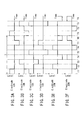
- FIGS. 1A and 1B are cross sectional views
schematically showing the construction of the
electrostatic actuator according to a first embodiment
of the present invention in a longitudinal direction of
the electrostatic actuator and in a direction
perpendicular to the longitudinal direction,
respectively;
- FIG. 2 schematically shows the constructions of
the first electrode array and the second electrode
array on the first stator section and the second stator
section shown in FIGS. 1A and 1B, respectively, as well
as the construction of the driving circuit;
- FIGS. 3A to 3F are timing charts for describing
the operation of the electrostatic actuator shown in
FIGS. 1A and 1B;
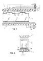
- FIG. 4 schematically shows how the first step is
performed for operating the electrostatic actuator
shown in FIGS. 1A and 1B;
- FIG. 5 schematically shows how the second step is
performed for operating the electrostatic actuator
shown in FIGS. 1A and 1B;
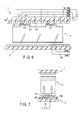
- FIG. 6 schematically shows how the third step is
performed for operating the electrostatic actuator
shown in FIGS. 1A and 1B;
- FIG. 7 schematically shows how the fourth step is
performed for operating the electrostatic actuator
shown in FIGS. 1A and 1B;
- FIG. 8 is a cross sectional view schematically
showing the construction of the electrostatic actuator
according to a second embodiment of the present
invention in a longitudinal direction of the
electrostatic actuator;
- FIG. 9 schematically shows the constructions of
the first electrode array and the second electrode
array on the first stator section and the second stator
section shown in FIG. 8, respectively, as well as the
construction of the driving circuit;
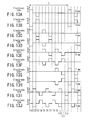
- FIGS. 10A to 10H are timing charts for describing
the operation of the electrostatic actuator shown in
FIG. 8;
- FIG. 11 schematically shows how the first step is
performed for operating the electrostatic actuator
shown in FIG. 8;
- FIG. 12 is a plan view schematically showing the
construction of the electrode array on the first stator
section in an electrostatic actuator according to a
third embodiment of the present invention;
- FIGS. 13A to 13J are timing charts for describing
the operation of the electrostatic actuator shown in
FIG. 12;
- FIG. 14 is a plan view schematically showing the
construction of the first electrode array on the first
stator section included in an electrostatic actuator
according to a fourth embodiment of the present
invention;
- FIG. 15 is a plan view schematically showing the
construction of the first electrode array on the first
stator section included in an electrostatic actuator
according to a fifth embodiment of the present
invention;
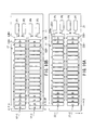
- FIG. 16A and 16B are a plan view schematically
showing the construction of the first and second
electrode arrays on the first and second stator
sections included in an electrostatic actuator
according to a sixth embodiment of the present
invention;
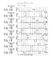
- FIGS. 17A to 17H are timing charts for describing
the operation of the electrostatic actuator shown in
FIG. 16;
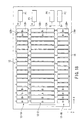
- FIG. 18 is a plan view schematically showing the
construction of the first electrode array on the first
stator section included in an electrostatic actuator
according to a seventh embodiment of the present
invention;
- FIG. 19 is a plan view schematically showing the
construction of the first electrode array on the first
stator section included in an electrostatic actuator
according to a eighth embodiment of the present
invention;
- FIG. 20 is a plan view schematically showing the
construction of the first electrode array on the first
stator section included in an electrostatic actuator
according to an ninth embodiment of the present
invention; and
- FIG. 21 is a plan view showing a small electronic
camera module according to a tenth embodiment of the
present invention, which is a modification of the
electrostatic actuator of the present invention.
-
-
Some embodiments of the present invention will now
be described with reference to the accompanying
drawings.
(First Embodiment)
-
FIGS. 1A and 1B collectively show the construction
of an electrostatic actuator according to a first
embodiment of the present invention; wherein FIG. 1A is
a cross sectional view showing the electrostatic
actuator in the longitudinal direction (X-direction),
and FIG. 1B is a cross section showing the
electrostatic actuator in a direction (Y-direction)
perpendicular to the longitudinal direction. FIG. 2
shows the planar shapes of the electrode arrays on the
first stator section and the second stator section as
well as the inner structure of the driving circuit.
The electrostatic actuator comprises a first stator
section 1 and a second stator section 2 arranged to
face each other, a movable section 3 arranged in a
space between the first stator section 1 and the second
stator section 2 and movable in the Y-direction, and a
driving circuit 4.
-
The first stator section 1 includes an insulating
substrate 11, a first electrode array 12 formed on the
substrate 11, and a dielectric film 13 formed to cover
the first electrode array 12. As shown in FIG. 2, the
first electrode array 12 includes a large number of
strip-like electrodes arranged at a predetermined pitch
P in the longitudinal direction of the substrate 11,
i.e., the first direction or the X-direction. In the
first electrode array 12, the electrode groups each
consisting of the first, second, third and fourth
electrodes are arranged in the electrode arranging
direction (X-direction) at the same period and at the
same interval. For the sake of the brevity, the first,
second, third and fourth electrodes are called the
electrodes 12A, 12B, 12C and 12D, and the capital
letters A, B, C, D are put in the drawing to the
wirings to these first to fourth electrodes,
respectively, so as to clarify the connecting
relationship.
-
As apparent from FIG. 1A, the first electrodes 12A
are commonly connected by a wiring 14A so as to be
connected to the driving circuit 4. Similarly, the
second electrodes 12B are commonly connected by the
wiring 14B so as to be connected to the driving circuit
4, and the third electrodes 12C are commonly connected
by the wiring 14C so as to be connected to the driving
circuit 4. Further, the fourth electrodes 12D are
commonly connected by the wiring 14D so as to be
connected to the driving circuit 4. The wiring 14 is
of a two layer structure having an insulating layer
interposed between the upper and lower conductive
layers. In other words, the wiring 14 is of a steric
wiring structure constructed such that one end of each
of the upper and lower conductive layers is connected
to the driving circuit 4.
-
The second stator section 2 includes an insulating
substrate 21, a second electrode array 22 formed on the
insulating substrate 21, and a dielectric film 23
formed to cover the upper surface of the second
electrode array 22. As shown in FIG. 2, the second
electrode array 22 includes two band- like electrodes
22M and 22N formed to extend in the longitudinal
direction of the substrate 21 (first direction or the
X-direction) apart from each other in the second
direction (Y-direction) perpendicular to the
X-direction. These electrodes 22M and 22N are
connected to the driving circuit 4.
-
As described above, the dielectric films 13 and 23
are formed on the first stator section 1 and the second
stator section 2, respectively. The dielectric film 13
serves to insulate the electrodes of the first
electrode array 12 from each other and to insulate the
electrodes of the first electrode array 12 from a fifth
electrode 33 on the movable section 3. Similarly, the
dielectric film 23 serves to insulate the electrodes of
the second electrode array 22 from each other and to
insulate each electrode of the second electrode array
22 from a sixth electrode 34 on the movable section 3.
-
In general, where a dielectric film is formed to
cover the electrodes included in the electrostatic
actuator, the moving operation of the movable section
is rendered unstable under the influence of the
dielectric polarization of the dielectric film. In the
electrostatic actuator according to the first
embodiment of the present invention, however, the
voltage application pattern to the electrodes is
improved so as to overcome the problem pointed out
above as described in detail herein later.
-
The movable section 3 is formed of a hollow
parallelepiped insulating substrate 31. The insulating
substrate 31 includes a convex portion 32 on the side
facing the first electrode array 12 on the first stator
section 1. The fifth electrode 33 is mounted to the
surface of the convex portion 32 facing the first
electrode array 12, and the sixth electrode 34 is
mounted to the surface of the convex portion 32 facing
the second electrode array 22 on the second stator
section 2. The movable section 3 is arranged movable
in the right-left direction (X-direction) in the moving
space between the first stator section 1 and the second
stator section 2. As shown in FIG. 1A, the size of the
electrode surface (width L) of the convex portion 32 in
the moving direction (X-direction) of the movable
section 3 is set at about 1.5 to 2.0 times as much as
the size (width Wa) of each of the electrodes 12A, 12B,
12C and 12D in the X-direction. On the other hand, the
fifth electrode 33 and the sixth electrode 34 are not
connected to the driving circuit 4 and are in an
electrically floating state so as to form so-called
"floating electrodes".
-
As shown in FIG. 2, the driving circuit 4 includes
two DC voltage sources 41, 42, two switching circuits
43, 44 serving to switch the DC voltage signals
generated from the DC voltage sources 41, 42 so as to
generate rectangular wave form voltage signals, and a
switch control circuit 45 serving to control the
outputs of the rectangular wave form voltage signals
generated from the switching circuits 43, 44. The
switching circuit 43 serving to connect the first
electrode array 12 to the DC voltage source 41 via the
wiring 14 includes an input terminal and an output
terminal. The output generated from the output
terminal is controlled by a control signal generated
from the switch control circuit 45 and supplied to the
input terminal. Likewise, the switching circuit 44
serving to connect the second electrode array 22 to the
DC voltage source 42 includes an input terminal and an
output terminal. The output generated from the output
terminal is controlled by a control signal generated
from the switch control circuit and supplied to the
input terminal. The switch control circuit 45 is
constructed to control the switching circuits 43, 44 in
accordance with a drive instruction signal S1 and
a direction instruction signal S2 generated from,
for example, a host computer (not shown).
-
The operation of the electrostatic actuator
according to the first embodiment of the present
invention will now be described with reference to
the time charts shown in FIGS. 3A to 3F and to the
operating states shown in FIGS. 4 to 7. FIGS. 3A to 3F
show the wave forms of the voltages applied to the
electrodes 12A, 12B, 12C, 12D, 22M and 22N, and FIGS. 4
to 7 show how the movable section 3 is moved.
-
In starting the operation, the drive instruction
signal S1 is supplied to the switch control circuit 45
so as to render the driving circuit 4 active. At the
same time, the direction instruction signal S2 is
supplied to the switch control circuit 45 so as to
determine whether the movable section 3 is moved to the
right or to the left in FIG. 1A. The following
description is on the basis that the movable section 3
is moved to the right unless otherwise pointed out
specifically.
-
In response to the drive instruction signal S1 and
the direction instruction signal S2, a positive voltage
and a negative voltage are applied from the DC voltage
source 41 to the electrode 12A and the electrode 12B,
respectively, through the switching circuit 43 for
a predetermined period T1, as shown in FIGS. 3A and 3B.
In this stage, the electrode 12A, the fifth electrode
33 and the electrode 12B collectively form a series
circuit including two capacitors, and a line E1 of
electric force runs through the electrode 12A, the
fifth electrode 33 and the electrode 12B. It should be
noted that the line E1 of electric force tends to
shrink as much as possible. As a result, an
electrostatic attractive force is generated between the
electrodes 12A, 12B and the fifth electrode 33 so as to
cause the movable section 3 to be moved toward the
first stator section 1.
-
In the next step, positive and negative voltages
are applied from the DC voltage source 42 to the
electrode 22M and 22N, respectively, through the
switching circuit 44 for a predetermined period T2, as
shown in FIGS. 3E and 3F. In this stage, the circuit
formed of the electrode 22M, the sixth electrode 34 and
the electrode 22N corresponds to an equivalent series
circuit including two capacitors so as to generate
a line E2 of electric force running through the
electrode 22M, the sixth electrode 34 and the electrode
22N, as shown in FIG. 5. The line E2 of electric
force thus generate also tends to shrink and, thus,
an electrostatic attractive force is generated between
the electrode 22M, 22N and the sixth electrode 34.
It follows that the movable section 3 is moved toward
the second stator section 2.
-
Further, a positive voltage and a negative voltage
are applied to the electrode 12B and the electrode 12C,
respectively, during a period T3 as shown in FIGS. 3B
and 3C. As a result, line E3 of electric force is
generated to run through the electrode 12B, the
fifth electrode 33 and the electrode 12C, and
an electrostatic attractive force is generated between
the electrodes 12B, 12C and the fifth electrode 33.
It follows that the movable section 3 is moved toward
the first stator section 1. It should be noted that
the electrodes 12B, 12C included in the first electrode
array 12 and having voltages applied thereto are
deviated by one pitch (P) from the electrodes 12A, 12B
to which the voltages were applied previously during
the period T1. It follows that the movable section 3
is moved to the right by one pitch P when moved toward
the first stator section 2.
-
In the next step, a positive voltage and a
negative voltage are applied to the electrode 22N and
the electrode 22M, respectively, during a period T4, as
shown in FIGS. 3E and 3F. As a result, a line E4 of
electric force is generated to run through the
electrode 22N, the sixth electrode 34 and the electrode
22M so as to generate an electrostatic attractive
force between the electrodes 22M, 22N and the
sixth electrode 34. It follows that the movable
section 3 is moved toward the second stator section.
-
Likewise, a positive voltage and a negative
voltage are applied to the electrode 12C and the
electrode 12D, respectively, during a period T5, as
shown in FIGS. 3C and 3D and, then, a positive voltage
and a negative voltage are applied to the electrode 22M
and the electrode 22N, respectively, during a period T6
like during the period T2, as shown in FIGS. 3E and 3F.
Then, a positive voltage and a negative voltage are
applied to the electrode 12D and the electrode 12A,
respectively, during a period T7, as shown in FIGS. 3D
and 3A and, then, a positive voltage and a negative
voltage are applied to the electrode 22N and the
electrode 22M, respectively, during a period T8 like
during the period T4, as shown in FIGS. 3E and 3F.
The operations described above are successively
performed so as to finish the operation of one period T
consisting of the periods T1 to T8 referred to above.
-
By the operation described above, the movable
section 3 is successively moved macroscopically pitch
by pitch in the arranging direction (X-direction) of
the first electrode array 12 on the first stator
section 1, i.e., to the right in FIG. 1A, while being
vibrated microscopically between the first stator
section 1 and the second stator section 2.
-
Where the direction instruction signal S2
instructing the movement of the movable section 3 to
the right in FIG. 1A is supplied to the switch control
circuit 45, the DC voltage is applied successively
between the electrodes 12D and 12A, between the
electrodes 22M and 22N, between the electrodes 12C and
12C, between the electrodes 22N and 22M, between the
electrodes 12B and 12C, between the electrodes 22M and
22N, between the electrodes 12A and 12B, and between
the electrodes 22N and 22M from the period T8 toward
the period T1 shown in FIGS. 3A to 3F. As a result,
the movable section 3 is successively moved
macroscopically to the left in FIG. 1A while being
vibrated between the first stator section 1 and the
second stator section 2.
-
In the electrostatic actuator of the first
embodiment described above, the movable section 3 is
alternately attracted by utilizing the electrostatic
force generated by applying the DC voltage between
the adjacent electrodes in any of the first electrode
array 12 on the first stator section 1 and the second
electrode array on the second stator section 2.
In other words, the movable section 3 is alternately
attracted by the shrinking function of the lines of
electric force running through the fifth electrode 33
and the sixth electrode 34 on the movable section 3.
Where the particular attracting function is utilized
for attracting the movable section 3, it suffices for
the fifth electrode 33 and the sixth electrode 34 on
the movable section 3 to be floating electrodes.
In other words, it is unnecessary to use a wiring for
connecting these third and fourth electrodes 33 and 34
to the driving circuit 34. It follows that the
particular construction is advantageous for the
improvement in the mass production capability and
the miniaturization of the electrostatic actuator.
In addition, it is possible to solve the problem in
respect of the reliability derived from the stress
application caused by the movement of the movable
section 3.
-
Further, if attentions are paid to a single
electrode in the first embodiment of the present
invention, the polarity of the applied DC voltage is
alternately reversed. For example, a positive voltage
is applied to the electrode 12A in the period T1 and,
then, a negative voltage is applied to the electrode
12A in the next period T3. This is also the case with
each of the electrodes 12B, 12C, 12D, 22M and 22N.
By the particular voltage application, the charging
caused by the dielectric polarization of the dielectric
films 13, 23 formed as a measure against the insulation
breakdown is canceled by the application of the voltage
of the opposite polarity. As a result, it is possible
to prevent the moving operation of the movable
section 3 from being rendered unstable by the
dielectric polarization.
-
In the first embodiment of the present invention,
the sixth electrode 34 on the movable section 3
is formed on the flat surface of the insulating
substrate 31. As a modification of the first
embodiment, it is also possible to form a convex
portion on the bottom surface of the insulating
substrate 31 in a manner to correspond to the
electrodes 22M and 22N constituting the second
electrode array 22 on the second stator section 2 and
to form the sixth electrode 34 on the convex portion.
It is also possible the entire movable section 3 to be
formed of a conductive material such that the portion
of the movable section 3 facing the electrodes 12A,
12B, 12C and 12D of the first electrode array 12 is
allowed to perform the function of the fifth electrode
33, and that the portion of the movable section 3
facing the electrodes 22M and 22N of the second
electrode array 22 is allowed to perform the function
of the sixth electrode 34. This is also the case with
any of the other embodiments described in the
following.
(Second Embodiment)
-
FIGS. 8 is a cross sectional view showing the
electrostatic actuator according to a first embodiment
of the present invention in the longitudinal direction
(X-direction), and FIG. 9 shows the planar shapes of
the electrode arrays on the first stator section and
the second stator section as well as the inner
structure of the driving circuit. The electrostatic
actuator as shown in FIGS. 1A, 1B and 2 is so called as
one-side propagation type in which only the first
stator section 1 applies a propagation force to the
movable section 3. In contrast, the electrostatic
actuator as shown in FIGS. 8 and 9 is so called as
both-side propagation type in which both of the first
and second stator sections 1, 2 apply the propagation
force to the movable section 3.
-
The electrostatic actuator shown in FIGS. 8 and 9
comprises a first stator section 1 having a same
configuration as that shown in FIG. 2, and a second
stator section 2 arranged to face the first stator
section, which includes a large number of strip-like
electrodes arranged at a predetermined pitch P in the
longitudinal direction of the substrate 11, i.e., the
first direction or the X-direction. In the second
stator section 2, an array of electrodes 22 is arranged
with a same phase as that of the first stator section 1
and has an arrangement of the electrode deviation by
P/2 pitch in respect to that of the first stator
section 1. In the second stator section 2, first
electrodes 22E are commonly connected by a wiring 24E
so as to be connected to the driving circuit 4.
Similarly, second electrodes 22F are commonly connected
by the wiring 24F so as to be connected to the driving
circuit 4, and third electrodes 22G are commonly
connected by the wiring 24G so as to be connected to
the driving circuit 4. Further, fourth electrodes 22H
are commonly connected by the wiring 24H so as to be
connected to the driving circuit 4. The wiring 24 is
of a two layer structure having an insulating layer
interposed between the upper and lower conductive
layers. In other words, the wiring 24 is of a steric
wiring structure constructed such that one end of each
of the upper and lower conductive layers is connected
to the driving circuit 4.
-
A movable section 3 is formed of a hollow
parallelepiped insulating substrate 31, as shown in
FIG. 8. The insulating substrate 31 includes a convex
portion 32 on the side facing the first electrode array
12 on the first stator section 1. The fifth electrode
33 is mounted to the surface of the convex portion 32
facing the first electrode array 12, and the sixth
electrode 34 is mounted to the surface of the convex
portion 32 facing the second electrode array 22 on
the second stator section 2. The movable section 3
is arranged movable in the right-left direction
(X-direction) in the moving space between the first
stator section 1 and the second stator section 2.
On the other hand, the fifth electrode 33 and the sixth
electrode 34 are not connected to the driving circuit 4
and are in an electrically floating state so as to form
so-called "floating electrodes".
-
As shown in FIG. 9, the driving circuit 4 includes
two DC voltage sources 41, 42, two switching circuits
43, 44 serving to switch the DC voltage signals
generated from the DC voltage sources 41, 42 so as to
generate rectangular wave form voltage signals, and
a switch control circuit 45 serving to control
the outputs of the rectangular wave form voltage
signals generated from the switching circuits 43, 44.
The switching circuit 43 serving to connect the first
electrode array 12 to the DC voltage source 41 via the
wiring 14 includes an input terminal and an output
terminal. The output generated from the output
terminal is controlled by a control signal generated
from the switch control circuit 45 and supplied to the
input terminal. Likewise, the switching circuit 44
serving to connect the second electrode array 22 to the
DC voltage source 42 includes an input terminal and an
output terminal. The output generated from the output
terminal is controlled by a control signal generated
from the switch control circuit and supplied to the
input terminal. The switch control circuit 45 is
constructed to control the switching circuits 43, 44 in
accordance with a drive instruction signal S1 and
a direction instruction signal S2 generated from,
for example, a host computer (not shown).
-
The operation of the electrostatic actuator
according to the second embodiment of the present
invention will now be described with reference to the
time charts shown in FIGS. 10A to 10H and to the
operating states shown in FIG. 11. FIGS. 10A to 10H
show the wave forms of the voltages applied to the
electrodes 12A, 12B, 12C, 12D, 22E, 22F, 22G and 22H,
and FIG. 11 show how the movable section 3 is moved.
-
In starting the operation, the drive instruction
signal S1 is supplied to the switch control circuit 45
so as to render the driving circuit 4 active. At the
same time, the direction instruction signal S2 is
supplied to the switch control circuit 45 so as to
determine whether the movable section 3 is moved to the
right or to the right in FIG. 8. The following
description is on the basis that the movable section 3
is moved to the right unless otherwise pointed out
specifically.
-
In response to the drive instruction signal S1 and
the direction instruction signal S2, a positive voltage
and a negative voltage are applied from the DC voltage
source 41 to the electrode 12A and the electrode 12B,
respectively, through the switching circuit 43 for a
predetermined period T1, as shown in FIGS. 11A and 11B.
In this stage, the electrode 12A, the electrode 33 and
the electrode 12B collectively form a series circuit
including two capacitors, and lines E1 of electric
force run through the electrode 12A, the electrode 33
and the electrode 12B. It should be noted that the
lines E1 of electric force tends to shrink as much as
possible. As a result, an electrostatic attractive
force is generated between the electrodes 12A, 12B and
the electrode 33 so as to cause the movable section 3
to be moved toward the first stator section 1.
-
In the next step, positive and negative voltages
are applied from the DC voltage source 42 to the
electrode 22G and 22H, respectively, through the
switching circuit 44 for a predetermined period T2, as
shown in FIGS. 10G and 10H. In this stage, the circuit
formed of the electrode 22G, the electrode 34 and the
electrode 22H corresponds to an equivalent series
circuit including two capacitors so as to generate
lines E2 of electric force running through the
electrode 22G, the electrode 34 and the electrode 22H.
The lines E2 of electric force thus generate also
tends to shrink and, thus, an electrostatic attractive
force is generated between the electrode 22G, 22H
and the electrode 34. It follows that the movable
section 3 is moved toward the second stator section 2.
The electrodes 22G, 22H of the first electrode
array 22, to which positive and negative voltages are
applied, are deviated by P/2 pitch from the electrodes
12A and 12B of the first electrode array 12 to which
voltages have been applied during the period T1.
Thus, the movable section 3 is moved by P/2 pitch in
the right direction at the time of moving the movable
section 2 from the first stator section 12 toward the
second stator section 22.
-
Further, a positive voltage and a negative voltage
are applied to the electrode 12B and the electrode 12C,
respectively, during a period T3 as shown in FIGS. 10B
and 10C. As a result, lines E3 of electric force
are generated to run through the electrode 12B,
the electrode 33 and the electrode 12C, and an
electrostatic attractive force is generated between the
electrodes 12B, 12C and the electrode 33. It follows
that the movable section 3 is moved toward the first
stator section 1. It should be noted that the
electrodes 12B, 12C included in the first electrode
array 12 and having voltages applied thereto are
deviated by one pitch (P) from the electrodes 12A, 12B
to which the voltages were applied previously during
the period T1. It follows that the movable section 3
is moved to the right when moved toward the first
stator section 2.
-
In the next step, a positive voltage and a
negative voltage are applied to the electrode 22E and
the electrode 22H, respectively, during a period T4, as
shown in FIGS. 10E and 10H. As a result, lines E4 of
electric force are generated to run through the
electrode 22E, the electrode 34 and the electrode 22H
so as to generate an electrostatic attractive force
between the electrodes 22E, 22H and the electrode 34.
It follows that the movable section 3 is moved toward
the second stator section 22.
-
Likewise, a positive voltage and a negative
voltage are applied to the electrode 12C and the
electrode 12D, respectively, during a period T5, as
shown in FIGS. 10C and 10D and, then, a positive
voltage and a negative voltage are applied to the
electrode 22E and the electrode 22F, respectively,
during a period T6 like during the period T2, as shown
in FIGS. 10E and 10F. Then, a positive voltage and
a negative voltage are applied to the electrode 12D and
the electrode 12A, respectively, during a period T7, as
shown in FIGS. 10D and 10A and, then, a positive
voltage and a negative voltage are applied to the
electrode 22F and the electrode 22G, respectively,
during a period T8 like during the period T4, as shown
in FIGS. 10F and 10G. The operations described above
are successively performed so as to finish the
operation of one period T consisting of the periods T1
to T8 referred to above.
-
By the operation described above, the movable
section 3 is successively moved macroscopically pitch
by pitch in the arranging direction (X-direction) of
the first electrode array 12 on the first stator
section 1, i.e., to the right in FIG. 8, while being
vibrated microscopically between the first stator
section 1 and the second stator section 2.
-
Where the direction instruction signal S2
instructing the movement of the movable section 3 to
the left in FIG. 8 is supplied to the switch control
circuit 45, the DC voltage is applied successively
between the electrodes 12D and 12A, between the
electrodes 22F and 22G, between the electrodes 12C and
12D, between the electrodes 22E and 22F, between the
electrodes 12B and 12C, between the electrodes 22M and
22N, between the electrodes 12A and 12B, and between
the electrodes 22H and 22E from the period T8 toward
the period T1 shown in FIGS. 10A to 10H. As a result,
the movable section 3 is successively moved
macroscopically to the left in FIG. 8 while being
vibrated between the first stator section 1 and the
second stator section 2.
(Third Embodiment)
-
In the first embodiment described above, the
electrodes forming the first electrode array 12 on
the first stator section 1 are aligned to form a single
row in the moving direction (first direction or
X-direction) of the movable section 3, and the DC
voltage is applied between the adjacent electrodes in
the X-direction of the first electrode array 12.
In the third embodiment of the present invention,
however, a first electrode group 12-1 and a second
electrode group 12-2 are arranged side by side so as to
form the first electrode array 12, as shown in FIG. 12.
In each of the first and second electrode groups 12-1
and 12-2, a plurality of electrodes are arranged in the
first direction (X-direction). Also, the first and
second electrode groups 12-1 and 12-2 are arranged
a predetermined distance apart from each other in the
second direction (Y-direction) perpendicular to the
first direction (X-direction). In the third embodiment
of the present invention, a DC voltage is applied
between the electrodes included in the first and second
electrode groups 12-1 and 12-2, i.e., between the
electrodes adjacent to each other in the Y-direction.
In short, the third embodiment clearly differs from the
first embodiment in the arrangement of the electrodes
on the stator section and in the manner of the voltage
application.
-
FIG. 12 is a plan view showing the first electrode
array 12 on the first stator section 1 included in
the electrostatic actuator according to the third
embodiment of the present invention. As shown in the
drawing, the first electrode array 12 includes the
first electrode group 12-1 consisting of electrodes
12A+, 12B+, 12C+, 12D+ and the second electrode group
12-2 consisting of electrodes 12A-, 12B-, 12C-, 12D-.
On the other hand, the second electrode array 22 on
the second stator section 2 consists of two band- like
electrodes 22M and 22N arranged a predetermined
distance apart from each other and extending in the
longitudinal direction (X-direction) of the substrate
21 as in the first embodiment shown in FIG. 2.
Further, the fifth electrode 33 is formed on the
movable section 3 in two rows in a manner to correspond
to the first and second electrode groups 12-1 and 12-2
of the first electrode array 12.
-
Incidentally, the symbols (+) and (-) put to the
electrodes of the first electrode array 12 do not imply
the positive (+) and negative (-) potentials used in
the electric field. Specifically, these symbols (+)
and (-) represent the relationship that, if the
potential of the electrode marked with the symbol (+)
is positive, the potential of the electrode marked with
the symbol (-) is negative, and that, if the potential
of the electrode marked with the symbol (+) is
negative, the potential of the electrode marked with
the symbol (-) is positive.
-
The electrodes 12A+, 12A-, the electrodes 12B+,
12B-, the electrodes 12C+, 12C-, and the electrodes
12D+, 12D- correspond to the electrodes 12A, 12B, 12C
and 12D, respectively, of the first embodiment.
The electrodes 12A+ are commonly connected to
a conductive pad P2. The electrodes 12B+ are commonly
connected to a conductive pad P1. The electrodes 12C+
are commonly connected to a conductive pad P3.
Further, the electrodes 12D+ are commonly connected to
a conductive pad P4. Likewise, the electrodes 12A-,
12B-, 12C- and 12D- are commonly connected to
conductive pads P7, P8, P6, and P5, respectively.
These conductive pads P1, P2, P3, P4, P5, P6, P7 and P8
are connected to the driving circuit 4, as in FIG. 2.
The driving circuit 4 comprises the DC voltage sources
41, 42, the switching circuits 43, 44, and the switch
control circuit 45, as shown in FIG. 2. However, the
driving circuit in the third embodiment differs from
the driving circuit 4 in the first embodiment shown in
FIG. 2 in the switching circuit 43 connected between
the DC voltage source 41 and the first electrode
array 12. Specifically, in the third embodiment of the
present invention, the switching circuit 43 has 8
output terminals, not 4 output terminals.
-
The operation of the electrostatic actuator
according to the third embodiment of the present
invention will now be described with reference to the
time charts shown in FIGS. 9A to 9J. Specifically,
FIGS. 9A to 9J show the wave forms of the voltages
applied to the electrode 12A+, the electrode 12A-, the
electrode 12B+, the electrode 12B-, the electrode 12C+,
the electrode 12C-, the electrode 12D+, the electrode
12D-, the electrode 22M and the electrode 22N,
respectively.
-
In the first step, a positive voltage is applied
to the electrode 12A+ as shown in FIG. 13A, a negative
voltage is applied to the electrode 12A- as shown in
FIG. 13B, a positive voltage is applied to the
electrode 12B+ as shown in FIG. 13C, and a negative
voltage is applied to the electrode 12B- as shown in
FIG. 13D. In this stage, each of the circuit formed of
the electrode 12A+, the fifth electrode 33 and the
electrode 12A- and the circuit formed of the electrode
12B+, the fifth electrode 33 and the electrode 12B-forms
an equivalent series circuit including two
capacitors. As a result, generated are lines of
electric force running through the route consisting of
the electrode 12A+, the fifth electrode 33, and the
electrode 12A- and the route consisting of the
electrode 12B+, the fifth electrode 33 and the
electrode 12B-. Since these lines of electric force
tend to shrink as much as possible, an electrostatic
attractive force is generated between the electrodes
12A+, 12A-, 12B+, 12B- and the fifth electrode 33, with
the result that the movable section 3 is moved toward
the first stator section 1.
-
In the next step, a positive voltage is applied to
the electrode M22 as shown in FIG. 13I and a negative
voltage is applied to the electrode N22 as shown in
FIG. 13J. In this stage, the circuit formed of the
electrode M22, the sixth electrode 34 and the electrode
N22 corresponds to a series equivalent circuit
including two capacitors and, thus, lines of electric
force are formed to run through the electrode M22, the
sixth electrode 34 and the electrode N22. Since the
lines of electric force thus formed tend to shrink as
much as possible, an electrostatic attractive force is
generated between the electrodes M22, N22 and the sixth
electrode 34, with the result that the movable section
3 is moved toward the second stator section 2.
-
In the next step, which is not absolutely
necessary, the voltages of the polarity opposite to
that of the voltages applied during the period T1 are
applied during a period T3 such that a negative voltage
is applied to the electrode 12A+, a positive voltage is
applied to the electrode 12A-, a negative voltage is
applied to the electrode 12B+, and a positive voltage
is applied to the electrode 12B-. Further, the
voltages of the polarity opposite to that of the
voltages applied during the period T2 are applied
during a period T4 such that a negative voltage is
applied to the electrode 22M, a positive voltage is
applied to the electrode 22N. Since the voltages of
the polarity opposite to that of the voltages applied
during the periods T1 and T2 are applied to the
electrodes 12A+, 12A-, 12B+, 12B-, 22M and 22N during
the periods T3 and T4, the charge generated by the
dielectric polarization of the dielectric films 13, 23
formed as a measure against the insulation breakdown is
discharged, with the result that the moving operation
of the movable section 3 is prevented from being
rendered unstable by the dielectric polarization.
-
Then, a positive voltage is applied to the
electrode 12B+ as shown in FIG. 13B, a negative voltage
is applied to the electrode 12B- as shown in FIG. 13D,
a positive voltage is applied to the electrode 1CB+ as
shown in FIG. 13E and a negative voltage is applied to
the electrode 12C- as shown in FIG. 13F. In this
stage, an electrostatic attractive force is generated
between the electrodes 12B+, 12B-, 12C+, 12c- and the
third electrode 3e3, with the result that the movable
section 3 is moved toward the first stator section 2.
It should be noted that the electrodes 12B+, 12B-,
12C+, 12C- of the first electrode array 12 to which the
voltage is applied are deviated by one pitch from
the electrodes 12A+, 12A-, 12B+, 12B- to which the
voltage was applied previously during the period T1.
It follows that the movable section 3 is moved to the
right by one pitch when moved toward the first stator
section 1. Then, a positive voltage is applied to the
electrode M22 and a negative voltage is applied to the
electrode N22 during a period T6 as shown in FIGS. 9I
and 9J. As a result, an electrostatic attractive force
is generated between the electrodes 22M, 22N and the
sixth electrode 34, with the result that the movable
section 3 is moved toward the second stator section 2.
-
Further, the voltages of the polarity opposite to
that of the voltages applied during the periods T5 and
T6 are applied during a period T7 as during the periods
T3 and T4 such that a negative voltage is applied to
the electrode 12B+ as shown in FIG. 13C, a positive
voltage is applied to the electrode 12B- as shown in
FIG. 13D, a negative voltage is applied to the
electrode 12C+ as shown in FIG. 13E, and a positive
voltage is applied to the electrode 12C- as shown in
FIG. 13F. Then, a negative voltage is applied to the
electrode M22 and a positive voltage is applied to the
electrode N22 during a period T8 as shown in FIGS. 9I
and 9J so as to cancel the charge produced by the
dielectric polarization of the dielectric films 13, 23.
It follows that the moving operation of the movable
section 3 is prevented from being rendered unstable by
the dielectric polarization.
-
Similarly, a first driving operation in which a DC
voltage is applied to two sets of the electrodes 12A+,
12B+, 12C+, 12D+ of the first electrode group 12-1 of
the first electrode array 12 and the electrodes 12A-,
12B-, 12C-, 12D- of the second electrode group 12-2 of
the first electrode array 12 and a second driving
operation in which a DC voltage is applied to
the electrodes M22, N22 are alternately repeated.
In addition, the positions of the electrodes of
the first electrode group 12-1 are successively
deviated by one pitch from the electrodes of the second
electrode group 12-2 during periods T9 to T12 such that
the driving operation for one period T is finished by
the periods T1 to T12.
-
By the driving operation described above, the
movable section 3 is macroscopically moved to the right
while being vibrated microscopically between the first
stator section 1 and the second stator section 2, as in
the first embodiment. If the order of applying the DC
voltage to the electrodes is made opposite to that
described above, the movable section 3 can be moved to
the left in FIG. 12.
-
The third embodiment described above produces the
effects similar to those produced by the first
embodiment described previously. In addition, the
third embodiment produces an additional prominent
effect. Specifically, in the first embodiment of the
present invention, the lines E1, E3, etc. of electric
force running through the adjacent electrodes of the
first electrode array 12 via the fifth electrode 33
contribute to the generation of the electrostatic
attractive force between the first stator section 1 and
the movable section 3. It is desirable for the size
(width Wa) of each of the electrodes constituting the
first electrode array 12 along the lines E1, E3, etc.
of electric force to be sufficiently larger than
the distance between the first stator section 1 and
the movable section 3. If the width Wa is small,
the lines E1, E3, etc. of electric force is decreased,
with the result that the lines of electric force
running through the side surfaces of the adjacent
electrodes of the first electrode array 12 without
running through the fifth electrode 33 is relatively
increased. It should be noted that the lines of
electric force that do not run through the fifth
electrode 33 do not contribute to the generation of
the electrostatic attractive force between the first
stator section 1 and the movable section 3. It follows
that it is undesirable for the lines of electric force,
which do not run through the fifth electrode 33, to be
increased, because the driving force of the movable
section 3 is decreased. If the arranging pitch of the
electrodes of the first electrode array 12 is
increased, it is possible to increase the width Wa of
the electrode so as to overcome the difficulty pointed
out above. If the electrode arranging pitch is
increased, however, the moving resolution of the
movable section 3 is decreased. In other words, the
moving amount per step is increased.
-
On the other hand, in the third embodiment of the
present invention, the lines of electric force running
through the electrodes 12A+, 12B+, 12C+, 12D+ of
the first electrode group 12-1 of the first electrode
array 12 and the electrodes 12A-, 12B-, 12C-, 12D- of
the second electrode group 12-2 of the first electrode
array 12 via the fifth electrode 33 contribute to the
generation of the electrostatic attractive force
between the first stator section 1 and the movable
section 3. In this case, it is desirable for the size
(length Wb) of the electrodes 12A+, 12B+, 12C+, 12D+,
12A-, 12B-, 12C-, 12D- along the lines of electric
force to be sufficiently large, compared with the
distance between the first stator section 1 and the
movable section 3. It should be note that the length
Wb can be increased easily regardless of the electrode
arranging pitch P of the first electrode array 12.
It follows that the lines of electric force running
through the side surfaces of the adjacent electrodes of
the first electrode array 12 without running through
the fifth electrode 33 are relatively decreased so as
to increase the driving force of the movable section 3.
(Fourth Embodiment)
-
FIG. 14 is a plan view showing the first electrode
array 12 of the first stator section 1 included in the
electrostatic actuator according to a fourth embodiment
of the present invention. As shown in the drawing, the
first electrode array 12 includes a first electrode
group 12-1 consisting of the electrodes 12A+ and 12B+,
a second electrode group 12-2 consisting of the
electrodes 12A- and 12B-, a third electrode group 12-3
consisting of the electrodes 12C+ and 12D+ and a fourth
electrode group 12-4 consisting of the electrodes 12C-and
12D-. These electrode groups 12-1, 12-4, 12-3 and
12-2 are arranged in the order mentioned.
-
The electrodes of the electrode groups 12-1 and
12-2 have an electrically paired relationship and are
arranged to extend in the X-direction at the same pitch
P and under the same phase. Likewise, the electrodes
of the electrode groups 12-3 and 12-4 have an
electrically paired relationship and are arranged to
extend in the X-direction at the same pitch P and under
the same phase. However, the phase of the electrodes
of the electrode groups 12-3 and 12-4 is deviated by
1/2 pitch (P/2) from the phase of the electrodes of the
electrode groups 12-1 and 12-2.
-
On the other hand, the second electrode array 22
on the second stator section 2 consists of two band- like
electrodes 22M and 22N formed on the substrate 21
a predetermined distance apart from each other and
extending in the longitudinal direction (X-direction)
of the substrate 21. Further, the fifth electrode 33
is formed in four rows on the movable section 3 in
a manner to correspond to the electrode groups 12-1,
12-2, 12-3, 12-4 of the first electrode array 12.
-
The electrode 12A+, the electrode 12B+,
the electrode 12C+, the electrode 12D+, the electrode
12A-, the electrode 12B-, the electrode 12C- and
the electrode 12D- correspond to the electrodes 12A,
12B, 12C and 12D in the first embodiment. The
electrode imparted with the same symbols are commonly
connected to the driving circuit through the pads P1,
P2, P3, P4, P5, P6, P7 and P8.
-
In the first step of the fourth embodiment of
the present invention, a positive voltage is applied to
the electrode 12A+ and a negative voltage is applied to
the electrode 12A- for a predetermined period so as to
generate lines of electric force running through the
electrode 12A+, the fifth electrode 33 and the
electrode 12A-. Since the lines of electric force
thus generated tend to shrink as much as possible,
an electrostatic attractive force is generated between
the electrode 12A+, 12A- and the fifth electrode 33,
with the result that the movable section 3 is moved
toward the first stator section 1. Then, a positive
voltage is applied to the electrode M22 and a negative
voltage is applied to the electrode N22 so as to
generate lines of electric force running through
the electrode 22M, the sixth electrode 34 and
the electrode N22. Since the lines of electric force
thus generated tend to shrink as much as possible,
an electrostatic force is generated between the
electrodes M22, N22 and the sixth electrode 34, with
the result that the movable section 3 is moved toward
the second stator section 2.
-
In the next step, a positive voltage is applied to
the electrode 12C+ and a negative voltage is applied to
the electrode 12C- for a predetermined period so as to
generate an electrostatic attractive force between the
electrodes 12C+, 12C- and the fifth electrode 33, with
the result that the movable section 3 is moved toward
the first stator section 1. Then, a negative voltage
is applied to the electrode 22M and a positive voltage
is applied to the electrode 22N so as to generate an
electrostatic attractive force between the electrodes
22M, 22N and the sixth electrode 34, with the result
that the movable section 3 is moved toward the second
stator section 2. It should be noted that the
positions of the electrodes 12C+ and 12C- of the first
electrode array 12 to which the voltages are applied
are deviated by 1/2 pitch (P/2) from the positions of
the electrodes 12A+ and 12A- to which the voltages were
applied previously, with the result that the movable
section 3 is moved by P/2 to the right when moved
toward the second stator section 2.
-
Likewise, a positive voltage is applied to the
electrode 12B+ and a negative voltage is applied to the
electrode 12B- for a predetermined period so as to
generate an electrostatic attractive force between the
electrodes 12B+, 12B- and the fifth electrode 33, with
the result that the movable section 3 is moved toward
the first stator section 1. Then, a positive voltage
is applied to the electrode 22M and a negative voltage
is applied to the electrode 22N so as to generate an
electrostatic attractive force between the electrodes
22M, 22N and the sixth electrode 34, with the result
that the movable section 3 is moved toward the second
stator section 2. Further, a positive voltage is
applied to the electrode 12D+ and a negative voltage is
applied to the electrode 12D- for a predetermined
period so as to generate an electrostatic attractive
force between the electrodes 12D+, 12D- and the fifth
electrode 33, with the result that the movable section
3 is moved toward the first stator section 1. Then,
a negative voltage is applied to the electrode 22M and
a positive voltage is applied to the electrode 22N so
as to generate an electrostatic attractive force
between the electrodes 22M, 22N and the sixth electrode
34, with the result that the movable section 3 is moved
toward the second stator section 2.
-
By the driving operation described above, the
movable section 3 is macroscopically moved to the right
while being vibrated microscopically between the first
stator section 1 and the second stator section 2, as in
the first embodiment. If the order of applying the DC
voltage to the electrodes is made opposite to that
described above, the movable section 3 can be moved to
the left in FIG. 14.
-
The fourth embodiment described above produces
the effects similar to those produced by the first
embodiment described previously. Also, in the first
embodiment, the movement resolution of the movable
section 3 (i.e., the moving distance per step) is equal
to the electrode arranging pitch P of the first
electrode array 12. In the fourth embodiment, however,
the movement resolution of the movable section 3 is
half the electrode arranging pitch P of the first
electrode array 12 so as to make it possible to achieve
the movement of a higher accuracy.
-
It should also be noted that, in the fourth
embodiment of the present invention, the connection
between the electrode and the pad can be achieved by a
planar wiring in place of a steric wiring so as to
improve the mass production capability of the
electrostatic actuator.
(Fifth Embodiment)
-
FIG. 15 is a plan view showing the first electrode
array 12 on the first stator section 1 included in an
electrostatic actuator according to a fifth embodiment
of the present invention. In the fifth embodiment
of the present invention, two electrode groups are
further added to the first electrode array 12 used in
the fourth embodiment of the present invention.
To be more specific, the first electrode array 12 in
the fifth embodiment includes a first electrode group
12-1 consisting of the electrodes 12A+ and 12B+,
a second electrode group 12-2 consisting of
the electrodes 12A- and 12B-, a third electrode group
12-3 consisting of the electrodes 12C+ and 12D+,
a fourth electrode group 12-4 consisting of the
electrodes 12C- and 12D-, a fifth electrode group 12-5
consisting of the electrodes 12E+ and 12F+, and a sixth
electrode group 12-6 consisting of the electrodes 12E-and
12F-,. These electrode groups 12-1, 12-2, 12-3,
12-4, 12-5 and 12-6 are arranged in the order
mentioned.
-
The electrodes of the electrode groups 12-1 and
12-2 have an electrically paired relationship and are
arranged to extend in the X-direction at the same pitch
P and under the same phase. Likewise, the electrodes
of the electrode groups 12-3 and 12-4 have an
electrically paired relationship and are arranged to
extend in the X-direction at the same pitch P and under
the same phase. Further, the electrodes of the
electrode groups 12-5 and 12-6 have an electrically
paired relationship and are arranged to extend in the
X-direction at the same pitch P and under the same
phase. However, the phase of the electrodes of the
electrode groups 12-5 and 12-6 is deviated by 1/3 pitch
(P/3) from the phase of the electrodes of the electrode
groups 12-3 and 12-4 and, thus, is deviated by 2/3
pitch (2P/3) from the phase of the electrodes of the
electrode groups 12-1 and 12-2.
-
On the other hand, the second electrode array 22
on the second stator section 2 consists of two band- like
electrodes 22M and 22N formed on the substrate 21
a predetermined distance apart from each other and
extending in the longitudinal direction (first
direction) of the substrate 21. Further, the third
electrode 34 is formed in six rows on the movable
section 3 in a manner to correspond to the electrode
groups 12-1, 12-2, 12-3, 12-4, 12-5 and 12-6 of the
first electrode array 12.
-
The electrodes 12A+, 12B+, 12C+, 12D+, 12E+, 12F+,
12A-, 12B-, 12C-, 12D-, 12E- and 12F- are commonly
connected to the driving circuit (not shown) through
pads P1 to P12, respectively.
-
In the first step of the fifth embodiment of the
present invention, a positive voltage is applied to the
electrode 12A+ and a negative voltage is applied to the
electrode 12A- for a predetermined period so as to
generate lines of electric force running through the
electrode 12A+, the fifth electrode 33 and the
electrode 12A- so as to generate an electrostatic
attractive force between the electrode 12A+, 12A- and
the fifth electrode 33, with the result that the
movable section 3 is moved toward the first stator
section 1. Then, a positive voltage is applied to
the electrode M22 and a negative voltage is applied to
the electrode N22 so as to generate an electrostatic
force between the electrodes M22, N22 and the sixth
electrode 34, with the result that the movable section
3 is moved toward the second stator section 2.
-
In the next step, a positive voltage is applied to
the electrode 12C+ and a negative voltage is applied to
the electrode 12C- for a predetermined period so as to
generate an electrostatic attractive force between the
electrodes 12C+, 12C- and the fifth electrode 33, with
the result that the movable section 3 is moved toward
the first stator section 1. Then, a negative voltage
is applied to the electrode 22M and a positive voltage
is applied to the electrode 22N so as to generate an
electrostatic attractive force between the electrodes
22M, 22N and the sixth electrode 34, with the result
that the movable section 3 is moved toward the second
stator section 2.
-
In the next step, a positive voltage is applied to
the electrode 12F+ and a negative voltage is applied to
the electrode 12F- for a predetermined period so as to
generate an electrostatic attractive force between the
electrodes 12C+, 12C- and the fifth electrode 33, with
the result that the movable section 3 is moved toward
the first stator section 1. Then, a negative voltage
is applied to the electrode 22M and a positive voltage
is applied to the electrode 22N so as to generate an
electrostatic attractive force between the electrodes
22M, 22N and the sixth electrode 34, with the result
that the movable section 3 is moved toward the second
stator section 2.
-
By the driving operation described above, the
movable section 3 is macroscopically moved to the right
while being vibrated microscopically between the first
stator section 1 and the second stator section 2, as in
the first embodiment. If the order of applying the DC
voltage to the electrodes is made opposite to that
described above, the movable section 3 can be moved to
the left in FIG. 15.
-
The fifth embodiment described above produces the
effects similar to those produced by the first
embodiment described previously. Also, in the fourth
first embodiment, the movement resolution of the
movable section 3 is one third of the electrode
arranging pitch P of the first electrode array 12 so as
to make it possible to achieve the movable section
movement of a higher accuracy. The technical idea of
the fifth embodiment readily suggests that it is
possible for the first electrode array to be formed of
a larger number of electrode groups. If the first
electrode array is formed of an n-number of electrode
groups, n being an even number, which are arranged side
by side in a manner to extend in the longitudinal
direction of the first stator section 1, the movement
resolution of the movable section 3 can be further
increased by deviating the phase of each of the
electrodes of the electrode groups by 1/(n/2) of
the electrode arranging pitch.
-
The fifth embodiment of the present invention is
equal to the fourth embodiment in that a steric wiring
is not required so as to make it possible to improve
the mass production capability of the electrostatic
actuator.
(Sixth Embodiment)
-
FIGS. 12A and 12B show the first electrode array
12 on the first stator section 1 and the second
electrode array 22 on the second stator section 22,
respectively, according to a sixth embodiment of the
present invention. As shown in FIG. 16A, the first
electrode array 12 includes a first electrode group
12-1 consisting of electrodes 12A+ and 12B+ each
arranged at a pitch P in a manner to extend in the
X-direction and a second electrode group 12-2
consisting of electrodes 12A- and 12B- each arranged at
a pitch P in a manner to extend in the X-direction.
On the other hand, the second electrode array 22
includes a first electrode group 22-1 consisting of
electrodes 12C+ and 12D+ each arranged at a pitch P in
a manner to extend in the X-direction and a second
electrode group 22-2 consisting of electrodes 12C- and
12D- each arranged at a pitch P in a manner to extend
in the X-direction. It should be noted, however, that
the phase of the electrodes of the second electrode
array 22 is deviated by 1/2 pitch (P/2) from the phase
of the electrodes of the first electrode array 12.
-
The electrodes 12A+, the electrodes 12B+, the
electrodes 12A- and the electrodes 12B- are commonly
connected to the driving circuit (not shown) through
the pads P1, P2, P3 and P4, respectivelsy. Likewise,
the electrode 12C+, the electrode 12D+, the electrode
12C- and the electrode 12D- belong to the groups of the
electrode 12C+, the electrode 12D+, the electrode 12C-and
the electrode 12D-, respectively, and are commonly
connected for each group to the driving circuit (not
shown) through the pads P5, P6, P7 and P8.
-
The operation of the electrostatic actuator
according to the sixth embodiment of the present
invention will now be described with reference to
FIGS. 17A to 17H. Specifically, FIGS. 17A to 13H show
the wave forms of the voltages applied to electrode
12A+, the electrode 12A-, the electrode 12B+, the
electrode 12B-, the electrode 12C+, the electrode 12C-,
the electrode 12D+, the electrode 12D-, respectively.
-
In the first step, a positive voltage is applied
to the electrode 12A+ on the first stator section 1 and
a negative voltage is applied to the electrode 12A- on
the first stator section 1 during a period T1 as shown
in FIGS. 17A and 17B. In this stage, the circuit
consisting of the electrode 12A+, the fifth electrode
33 and the electrode 12A- equivalently corresponds to
a series circuit including two capacitors so as to
generate lines of electric force running through
the electrode 12A+, the fifth electrode 33 and the
electrode 12A-. Since the lines of electric force
thus generated tend to shrink as much as possible,
an electrostatic attractive force is generated between
the electrodes 12A+, 12A- and the fifth electrode 33,
with the result that the movable section 3 is moved
toward the first stator section 1.
-
Then, a positive voltage is applied to the
electrode 12C+ on the second stator section 2 and
a negative voltage is applied to the electrode 12C- on
the second stator section 2 during a period T2 as shown
in FIGS. 17E and 17F. In this stage, the circuit
consisting of the electrode 12C+, the sixth electrode
34 and the electrode 12C- equivalently corresponds to
a series circuit including two capacitors so as to
generate lines of electric force running through the
electrode 12C+, the sixth electrode 34 and the
electrode 12C-. Since the lines of electric force
thus generated tend to shrink as much as possible,
an electrostatic attractive force is generated between
the electrodes 12C+, 12C- and the fifth electrode 33,
with the result that the movable section 3 is moved
toward the second stator section 2. It should be noted
that the phase of the electrodes 12C+, 12C- is deviated
by P/2 from the phase of the electrodes 12A+, 12A-,
with the result that the movable section 3 is moved to
the right in FIG. 16 by P/2 when moved to the second
stator section 2.
-
In the next step, a positive voltage is applied to
the electrode 12B+ on the first stator section 1 and
a negative voltage is applied to the electrode 12B- on
the first stator section 1 during a period T3 as shown
in FIGS. 17C and 17D. In this stage, lines of electric
force are generated in a manner to run through
the electrode 12B+, the fifth electrode 33 and the
electrode 12B-. As a result, an electrostatic
attractive force is generated between the electrodes
12B+, 12B- and the fifth electrode 33, with the result
that the movable section 3 is moved toward the first
stator section 1. It should be noted that the phase of
the electrodes 12B+, 12B- is deviated by P/2 from
the phase of the electrodes 12A+, 12A-, with the result
that the movable section 3 is moved to the right
in FIG. 16 by P/2 when moved to the first stator
section 1.
-
Then, a positive voltage is applied to the
electrode 12D+ on the second stator section 2 and
a negative voltage is applied to the electrode 12D- on
the second stator section 2 during a period T4 as shown
in FIGS. 17G and 17H. As a result, lines of electric
force are generated to run through the electrode 12D+,
the sixth electrode 34 and the electrode 12D-, and
an electrostatic attractive force is generated between
the electrodes 12D+, 12D- and the sixth electrode 34,
with the result that the movable section 3 is moved
toward the second stator section 2. It should be noted
that the phase of the electrodes 12D+, 12D- is deviated
by P/2 from the phase of the electrodes 12C+, 12C-,
with the result that the movable section 3 is moved to
the right in FIG. 16 by P/2 when moved to the second
stator section 2.
-
By the driving operation described above, the
movable section is macroscopically moved to the right
in FIG. 16 while being vibrated microscopically between
the first stator section and the second stator section.
The movable section 3 can be moved to the left in
FIG. 16 by making opposite the order of applying a DV
voltage to the electrodes.
-
Likewise, a DC voltage is applied successively to
the electrode 12A+, the electrode 12A-, the electrode
12B+, the electrode 12B-, the electrode 12C+, the
electrode 12C-, the electrode 12D+ and the electrode
12D- during periods T4 to T8, and the driving operation
of one period T is finished by the periods T1 to T8.
It should be noted in this connection that the polarity
of the DC voltage applied during the periods T5 to T8
is opposite to that of the DC voltage applied during
the periods T1 to T4, as apparent from FIGS. 17A to
17H, with the result that the charge produced by the
dielectric polarization of the dielectric films 13, 23
is canceled as in the embodiments described previously.
It follows that the moving operation of the movable
section 3 is prevented from being rendered unstable by
the dielectric polarization.
(Seventh Embodiment)
-
FIG. 18 is a plan view showing the first electrode
array 12 on the first stator section 1 according to
a seventh embodiment of the present invention. The
seventh embodiment of the present invention differs
from the sixth embodiment in that the first electrode
group 12-1 in the sixth embodiment consisting of the
electrodes 12A+ and 12B+ is divided into electrode
groups 12-1A and 12-B, and these electrode groups 12-1A
and 12-B are arranged on both sides of the second
electrode group 12-2 consisting of the electrodes 12A-and
12B-. The electrodes belonging to the same group
of the divided electrode groups 12-1A and 12-1B are
commonly connected by wirings, and these divided
electrode groups 12-1A and 12-B collectively perform
the function of a single electrode group.
-
On the other hand, the phase of the electrodes of
the second electrode array (not shown) on the second
stator section 2 is deviated by 1/2 pitch from the
phase of the electrodes of the first electrode array as
in the sixth embodiment. The driving operation of the
seventh embodiment is equal to that of the sixth
embodiment and, thus, the description is omitted in
respect of the driving operation of the seventh
embodiment.
-
The seventh embodiment produces the effects
similar to those produced by the first to sixth
embodiments described previously and an additional
effect as described in the following. Specifically, in
each of the first to sixth embodiments, the point at
which the electrostatic attractive force produced
between the first stator section 1 or the second stator
section 2 and the movable section 3 is rendered maximum
is positioned in the center in the Y-direction, with
the result that it is possible for the movable section
3 to be swung to the right or left about the center in
the Y-direction. In the seventh embodiment, however,
the point where the electrostatic attractive force is
rendered maximum is positioned in two points deviant
to the right and the left from the center in the
Y-direction, with the result that the movable section 3
is unlikely to be swung. In conclusion, the seventh
embodiment is advantageous over the first to seventh
embodiments in that it is possible to stabilize the
behavior and the posture of the movable section 3.
(Eighth Embodiment)
-
FIG. 19 is a plan view showing the first electrode
array 12 on the first stator section 1 according
to a eighth embodiment of the present invention.
The eighth embodiment differs from the sixth embodiment
in that the electrode 12B+ in the sixth embodiment is
divided in the second direction (Y-direction) into
three electrodes, and the divided electrodes 12B- are
arranged between the adjacent electrodes 12A+. These
divided electrodes 12B- are commonly connected by
a wiring and collectively perform the function of
a single electrode group.
-
On the other hand, the phase of the electrodes of
the second electrode array (not shown) on the second
stator section 2 is deviated by 1/2 pitch from the
phase of the electrodes of the first electrode array as
in the sixth embodiment. The driving operation of the
eighth embodiment is equal to that of the sixth
embodiment and, thus, the description is omitted in
respect of the driving operation of the eighth
embodiment.
-
The eighth embodiment produces the effects similar
to those produced by the seventh embodiment and an
additional effect as described in the following.
Specifically, it is possible to improve the wiring
efficiency of the electrodes 12A+ and the electrodes
12B+ as apparent from FIG. 19. It follows that the
eighth embodiment is advantageous in that, if the area
of the substrate 11 is the same, it is possible to
increase the effective area of the electrode, leading
to an improved driving capability of the movable
section 3.
(Ninth Embodiment)
-
FIG. 20 is a plan view showing the construction of
the second electrode array 22 on the second stator
section 2 according to an ninth embodiment of the
present invention. As shown in the drawing, the second
electrode array 22 includes the electrodes 22M and 22N
as in the first embodiment. What should be noted is
that each of these electrodes 22M and 22N is in the
shape of comb teeth, and the teeth of these electrodes
22M and 22N are meshed with each other in a con-contact
fashion. The second electrode array 22 of the
particular construction produces the effect similar to
that produced by the second electrode array 22 used in
the first embodiment.
(Tenth Embodiment)
-
An application of the electrostatic actuator
of the present invention will now be described.
The electrostatic actuator of the present invention
permits producing efficient driving characteristics
with a small power consumption and, thus, is adapted
for use as, for example, the focus adjusting mechanism
of a small electronic camera.
-
FIG. 21 shows the module portion of a small
electronic camera using the electrostatic actuator
according to the ninth embodiment of the present
invention in the focus adjusting mechanism. As shown
in the drawing, a solid state image pick-up element 101
formed of a CMOS or a CCD is arranged on a substrate
100, and an electrostatic actuator 102 is mounted to
the solid state image pick-up element 101. In the
electrostatic actuator 102, a lens 5 is integrally
mounted to the movable section 3 as shown in FIG. 1.
Also, the driving circuit 4 of the electrostatic
actuator 102 and an IC chip 103 including, for example,
a DSP (digital signal processor) chip for controlling
the driving circuit 4 are mounted to the substrate 100.
-
The electronic camera module can be formed very
small as shown in FIG. 21 and is adapted for use in,
for example, a portable telephone and a digital camera.