EP1202016B1 - Air-conditioning system with internal heat exchanger and heat exchanger tube for same - Google Patents
Air-conditioning system with internal heat exchanger and heat exchanger tube for same Download PDFInfo
- Publication number
- EP1202016B1 EP1202016B1 EP01124090A EP01124090A EP1202016B1 EP 1202016 B1 EP1202016 B1 EP 1202016B1 EP 01124090 A EP01124090 A EP 01124090A EP 01124090 A EP01124090 A EP 01124090A EP 1202016 B1 EP1202016 B1 EP 1202016B1
- Authority
- EP
- European Patent Office
- Prior art keywords
- heat exchanger
- exchanger tube
- exchanger according
- outer channels
- central channel
- Prior art date
- Legal status (The legal status is an assumption and is not a legal conclusion. Google has not performed a legal analysis and makes no representation as to the accuracy of the status listed.)
- Expired - Lifetime
Links
Images
Classifications
-
- B—PERFORMING OPERATIONS; TRANSPORTING
- B60—VEHICLES IN GENERAL
- B60H—ARRANGEMENTS OF HEATING, COOLING, VENTILATING OR OTHER AIR-TREATING DEVICES SPECIALLY ADAPTED FOR PASSENGER OR GOODS SPACES OF VEHICLES
- B60H1/00—Heating, cooling or ventilating [HVAC] devices
- B60H1/00321—Heat exchangers for air-conditioning devices
- B60H1/00342—Heat exchangers for air-conditioning devices of the liquid-liquid type
-
- B—PERFORMING OPERATIONS; TRANSPORTING
- B60—VEHICLES IN GENERAL
- B60H—ARRANGEMENTS OF HEATING, COOLING, VENTILATING OR OTHER AIR-TREATING DEVICES SPECIALLY ADAPTED FOR PASSENGER OR GOODS SPACES OF VEHICLES
- B60H1/00—Heating, cooling or ventilating [HVAC] devices
- B60H1/32—Cooling devices
- B60H1/3204—Cooling devices using compression
- B60H1/3227—Cooling devices using compression characterised by the arrangement or the type of heat exchanger, e.g. condenser, evaporator
-
- B—PERFORMING OPERATIONS; TRANSPORTING
- B60—VEHICLES IN GENERAL
- B60H—ARRANGEMENTS OF HEATING, COOLING, VENTILATING OR OTHER AIR-TREATING DEVICES SPECIALLY ADAPTED FOR PASSENGER OR GOODS SPACES OF VEHICLES
- B60H1/00—Heating, cooling or ventilating [HVAC] devices
- B60H1/32—Cooling devices
- B60H1/3204—Cooling devices using compression
- B60H1/3229—Cooling devices using compression characterised by constructional features, e.g. housings, mountings, conversion systems
-
- F—MECHANICAL ENGINEERING; LIGHTING; HEATING; WEAPONS; BLASTING
- F25—REFRIGERATION OR COOLING; COMBINED HEATING AND REFRIGERATION SYSTEMS; HEAT PUMP SYSTEMS; MANUFACTURE OR STORAGE OF ICE; LIQUEFACTION SOLIDIFICATION OF GASES
- F25B—REFRIGERATION MACHINES, PLANTS OR SYSTEMS; COMBINED HEATING AND REFRIGERATION SYSTEMS; HEAT PUMP SYSTEMS
- F25B40/00—Subcoolers, desuperheaters or superheaters
-
- F—MECHANICAL ENGINEERING; LIGHTING; HEATING; WEAPONS; BLASTING
- F28—HEAT EXCHANGE IN GENERAL
- F28D—HEAT-EXCHANGE APPARATUS, NOT PROVIDED FOR IN ANOTHER SUBCLASS, IN WHICH THE HEAT-EXCHANGE MEDIA DO NOT COME INTO DIRECT CONTACT
- F28D7/00—Heat-exchange apparatus having stationary tubular conduit assemblies for both heat-exchange media, the media being in contact with different sides of a conduit wall
- F28D7/0008—Heat-exchange apparatus having stationary tubular conduit assemblies for both heat-exchange media, the media being in contact with different sides of a conduit wall the conduits for one medium being in heat conductive contact with the conduits for the other medium
-
- F—MECHANICAL ENGINEERING; LIGHTING; HEATING; WEAPONS; BLASTING
- F28—HEAT EXCHANGE IN GENERAL
- F28D—HEAT-EXCHANGE APPARATUS, NOT PROVIDED FOR IN ANOTHER SUBCLASS, IN WHICH THE HEAT-EXCHANGE MEDIA DO NOT COME INTO DIRECT CONTACT
- F28D7/00—Heat-exchange apparatus having stationary tubular conduit assemblies for both heat-exchange media, the media being in contact with different sides of a conduit wall
- F28D7/10—Heat-exchange apparatus having stationary tubular conduit assemblies for both heat-exchange media, the media being in contact with different sides of a conduit wall the conduits being arranged one within the other, e.g. concentrically
- F28D7/106—Heat-exchange apparatus having stationary tubular conduit assemblies for both heat-exchange media, the media being in contact with different sides of a conduit wall the conduits being arranged one within the other, e.g. concentrically consisting of two coaxial conduits or modules of two coaxial conduits
-
- F—MECHANICAL ENGINEERING; LIGHTING; HEATING; WEAPONS; BLASTING
- F28—HEAT EXCHANGE IN GENERAL
- F28F—DETAILS OF HEAT-EXCHANGE AND HEAT-TRANSFER APPARATUS, OF GENERAL APPLICATION
- F28F1/00—Tubular elements; Assemblies of tubular elements
- F28F1/02—Tubular elements of cross-section which is non-circular
- F28F1/022—Tubular elements of cross-section which is non-circular with multiple channels
-
- F—MECHANICAL ENGINEERING; LIGHTING; HEATING; WEAPONS; BLASTING
- F28—HEAT EXCHANGE IN GENERAL
- F28F—DETAILS OF HEAT-EXCHANGE AND HEAT-TRANSFER APPARATUS, OF GENERAL APPLICATION
- F28F1/00—Tubular elements; Assemblies of tubular elements
- F28F1/10—Tubular elements and assemblies thereof with means for increasing heat-transfer area, e.g. with fins, with projections, with recesses
- F28F1/40—Tubular elements and assemblies thereof with means for increasing heat-transfer area, e.g. with fins, with projections, with recesses the means being only inside the tubular element
-
- F—MECHANICAL ENGINEERING; LIGHTING; HEATING; WEAPONS; BLASTING
- F28—HEAT EXCHANGE IN GENERAL
- F28F—DETAILS OF HEAT-EXCHANGE AND HEAT-TRANSFER APPARATUS, OF GENERAL APPLICATION
- F28F7/00—Elements not covered by group F28F1/00, F28F3/00 or F28F5/00
- F28F7/02—Blocks traversed by passages for heat-exchange media
-
- F—MECHANICAL ENGINEERING; LIGHTING; HEATING; WEAPONS; BLASTING
- F28—HEAT EXCHANGE IN GENERAL
- F28F—DETAILS OF HEAT-EXCHANGE AND HEAT-TRANSFER APPARATUS, OF GENERAL APPLICATION
- F28F9/00—Casings; Header boxes; Auxiliary supports for elements; Auxiliary members within casings
- F28F9/02—Header boxes; End plates
- F28F9/0246—Arrangements for connecting header boxes with flow lines
- F28F9/0251—Massive connectors, e.g. blocks; Plate-like connectors
-
- F—MECHANICAL ENGINEERING; LIGHTING; HEATING; WEAPONS; BLASTING
- F25—REFRIGERATION OR COOLING; COMBINED HEATING AND REFRIGERATION SYSTEMS; HEAT PUMP SYSTEMS; MANUFACTURE OR STORAGE OF ICE; LIQUEFACTION SOLIDIFICATION OF GASES
- F25B—REFRIGERATION MACHINES, PLANTS OR SYSTEMS; COMBINED HEATING AND REFRIGERATION SYSTEMS; HEAT PUMP SYSTEMS
- F25B2309/00—Gas cycle refrigeration machines
- F25B2309/06—Compression machines, plants or systems characterised by the refrigerant being carbon dioxide
- F25B2309/061—Compression machines, plants or systems characterised by the refrigerant being carbon dioxide with cycle highest pressure above the supercritical pressure
-
- F—MECHANICAL ENGINEERING; LIGHTING; HEATING; WEAPONS; BLASTING
- F25—REFRIGERATION OR COOLING; COMBINED HEATING AND REFRIGERATION SYSTEMS; HEAT PUMP SYSTEMS; MANUFACTURE OR STORAGE OF ICE; LIQUEFACTION SOLIDIFICATION OF GASES
- F25B—REFRIGERATION MACHINES, PLANTS OR SYSTEMS; COMBINED HEATING AND REFRIGERATION SYSTEMS; HEAT PUMP SYSTEMS
- F25B9/00—Compression machines, plants or systems, in which the refrigerant is air or other gas of low boiling point
- F25B9/002—Compression machines, plants or systems, in which the refrigerant is air or other gas of low boiling point characterised by the refrigerant
- F25B9/008—Compression machines, plants or systems, in which the refrigerant is air or other gas of low boiling point characterised by the refrigerant the refrigerant being carbon dioxide
Landscapes
- Engineering & Computer Science (AREA)
- Physics & Mathematics (AREA)
- Thermal Sciences (AREA)
- Mechanical Engineering (AREA)
- General Engineering & Computer Science (AREA)
- Geometry (AREA)
- Heat-Exchange Devices With Radiators And Conduit Assemblies (AREA)
- Air-Conditioning For Vehicles (AREA)
Description
Die Erfindung betrifft ein Wärmetauscherrohr, einen mit einem solchen Wärmetauscherrohr aufgebauten Wärmetauscher sowie eine Klimaanlage mit einem solchen Wärmetauscher.The invention relates to a heat exchanger tube, a constructed with such a heat exchanger tube heat exchanger and an air conditioner with such a heat exchanger.
Klimaanlagen, insbesondere Klimaanlagen von Kraftfahrzeugen, beinhalten in der Regel eine Kältemaschine, die nach dem Kompressionsprinzip arbeitet. Die Hauptkomponenten einer solchen Kompressions-Kältemaschine sind ein Verdichter (Kompressor), ein Kühler (oder Kondensator), ein Expansionsventil, ein Verdampfer und ein innerer Wärmetauscher zur Abkühlung des als Kältemittel zum Expansionsventil geleiteten Fluids und zum Erwärmen des aus dem Verdampfer kommenden entspannten Kältemittels im Gegenstrom.Air conditioning systems, especially air conditioning systems of motor vehicles, usually include a chiller that operates on the principle of compression. The main components of such a compression refrigerating machine are a compressor, a cooler (or condenser), an expansion valve, an evaporator, and an internal heat exchanger for cooling the refrigerant supplied as a refrigerant to the expansion valve and for heating the expanded refrigerant coming out of the evaporator countercurrent.
Als Alternative zu herkömmlichen Kältemitteln werden seit einiger Zeit Fluide vorgeschlagen, die einen höheren Betriebsdruck erfordern. Ein solches Fluid ist bspw. CO2. Derartige Kältemittel erfordern einen erhöhten Anlagendruck, wobei die Anlagen aus Sicherheitsgründen bis zu Berstdrücken von 700 bar ausgelegt werden müssen.As an alternative to conventional refrigerants fluids have been proposed for some time, requiring a higher operating pressure. Such a fluid is, for example, CO 2 . Such refrigerants require an increased system pressure, the systems must be designed for safety reasons up to burst pressures of 700 bar.
Der Betrieb einer Kältemaschine mit hohem Betriebsdruck von über 60 bar unterliegt in Kraftfahrzeugen besonderen Sicherheitsanforderungen. Diese können nicht ohne Weiteres lediglich durch eine Verstärkung herkömmlicher Komponenten einer Klimaanlage erfüllt werden, um nicht das Anlagengewicht zu hoch werden zu lassen. Für Kraftfahrzeuge vorgesehene Klimaanlagen und Kältemaschinen müssen möglichst leicht sein. Darüber hinaus müssen sie so beschaffen sein, dass sich eine möglichst kostengünstige und prozesssichere Fertigung ergibt. Diese allgemeinen Forderungen treffen auch auf den inneren Wärmetauscher einer Kraftfahrzeug-Klimaanlage zu. Ein solcher Wärmetauscher weist zwei in Wärmeaustausch miteinander stehende Kanäle auf. Zusätzlich zu den genannten Schwierigkeiten ergibt sich hier die Problematik, dass die Kanäle nicht nur von unterschiedlich warmen Medien durchströmt werden, sondern auch unterschiedlichen Drücken ausgesetzt sind. Die Druckunterschiede zwischen beiden Kanälen sind bei Hochdruck-Kältemaschinen erheblich. Dennoch dürfen die Drücke nicht zur Beschädigung des Wärmetauschers führen. Darüber hinaus ist ein möglichst guter Wärmeaustausch sicherzustellen. Dies kann eine besondere Schwierigkeit darstellen, wenn überkritische Drücke erreicht werden, bei denen zwischen flüssiger und gasförmiger Phase des Kältemittels nicht mehr zu unterscheiden ist. Auch bei solchen Betriebszuständen muss ein gewünschter Wärmeaustausch zwischen beiden Kanälen sichergestellt sein.The operation of a chiller with a high operating pressure of over 60 bar is subject to special safety requirements in motor vehicles. These can not be readily met by merely amplifying conventional components of an air conditioner so as not to make the system weight too high. For motor vehicles provided air conditioning and refrigeration must be as easy as possible. In addition, they must be designed so that the most cost-effective and process-reliable manufacturing results. These general requirements also apply to the internal heat exchanger of a motor vehicle air conditioning system. Such a heat exchanger has two channels in heat exchange with each other. In addition to the difficulties mentioned here arises the problem that the channels are not only flowed through by different warm media, but are also exposed to different pressures. The pressure differences between both channels are significant in high pressure chillers. Nevertheless, the pressures must not lead to damage to the heat exchanger. In addition, ensure the best possible heat exchange. This can be a particular difficulty when supercritical pressures are reached in which no distinction is made between the liquid and gaseous phases of the refrigerant. Even with such operating conditions, a desired heat exchange between the two channels must be ensured.
Ein für Freon - d.h. ein herkömmliches Kältemittel geeignetes Wärmetauscherrohr ist aus der GB-B-1 032 990 zu entnehmen. Das Wärmetauscherrohr weist ein zentrales Rohr mit nach innen ragenden Rippen und auf einem Kranz um diesen herum gruppierte Kanäle auf, die voneinander durch radial orientierte Wände getrennt sind. Außen ist das Wärmetauscherrohr durch einen zylindrischen Mantel abgeschlossen.One for freon - i. a conventional refrigerant suitable heat exchanger tube is shown in GB-B-1 032 990. The heat exchanger tube has a central tube with inwardly projecting ribs and channels grouped around it on a rim separated by radially oriented walls. Outside, the heat exchanger tube is closed by a cylindrical shell.
Des weiteren offenbart die DE-A-199 03 833 einen Wärmetauscher mit einem Wärmetauscherrohr, das einen Zentralkanal und um diesen herum angeordnete Außenkanäle aufweist. Das Wärmetauscherrohr ist als Rohrschlange in einem Behälter angeordnet. Während der Zentralkanal als Rohr in den Behälter hineinführt und aus diesem herausgeführt ist, sind die Außenkanäle innerhalb des Behälters offen, um einen Fluidzustrom und einen Fluidabstrom zu ermöglichen.Furthermore, DE-A-199 03 833 discloses a heat exchanger with a heat exchanger tube, which has a central channel and arranged around these outer channels. The heat exchanger tube is arranged as a tube coil in a container. While the central channel is leading into and out of the container as a tube, the outer channels within the container are open to allow for fluid flow and fluid outflow.
Es ist Aufgabe der Erfindung, einen für Hochdruck-Kältemaschinen geeigneten Wärmetauscher sowie eine Klimaanlage mit einem solchen Wärmetauscher zu schaffen.It is an object of the invention to provide a suitable for high pressure refrigeration heat exchanger and an air conditioner with such a heat exchanger.
Diese Aufgabe wird durch einen Wärmetauscher mit den Merkmalen des Patentanspruchs 1 gelöst.This object is achieved by a heat exchanger having the features of
Der erfindungsgemäße Wärmetauscher enthält ein Wärmetauscherrohr, das ein Mehrkammer-Profil mit einem Zentralkanal und mit mehreren um den Zentralkanal herum gruppierten Außenkanälen festlegt. Dabei ist der Zentralkanal vorzugsweise mittig (zentral) in dem Wärmetauscherrohr angeordnet, d.h. die Mittellinie des Zentralkanals stimmt mit der Mittellinie des Wärmetauscherrohrs überein. Die Außenkanäle sind konzentrisch zu dem Zentralkanal angeordnet und voneinander durch Zwischenwände getrennt. Die Zwischenwände erstrecken sich somit etwa in Radialrichtung bezüglich des Zentralkanals bzw. seiner Mittellinie. Sie wirken somit aussteifend für das Wärmetauscherrohr und gestatten es, den Zentralkanal besonders druckfest auszulegen. Bei einem Kanaldurchmesser von etwa 5mm werden schon bei geringen sonstigen Wandstärken des Wärmetauscherrohrs von bspw. 1mm bis 2mm und Aluminium als Werkstoff Druckfestigkeiten von mehreren 100 bar erreicht.The heat exchanger according to the invention includes a heat exchanger tube defining a multi-chamber profile having a central channel and a plurality of outer channels grouped around the central channel. In this case, the central channel is preferably arranged centrally in the heat exchanger tube, ie the center line of the central channel coincides with the center line of the heat exchanger tube. The outer channels are arranged concentrically to the central channel and separated from each other by partitions. The intermediate walls thus extend approximately in the radial direction with respect to the central channel or its Centerline. They thus act stiffening the heat exchanger tube and allow it to interpret the central channel particularly pressure resistant. With a channel diameter of about 5 mm, compressive strengths of several 100 bar are achieved even with small other wall thicknesses of the heat exchanger tube of, for example, 1 mm to 2 mm and aluminum as the material.
Der Zentralkanal weist vorzugsweise eine von der Zylinderform abweichende Form auf. Es sind an der Wandung des Zentralkanals Vorsprünge angeformt, die sich in den Zentralkanal hinein erstrecken. Die Vorsprünge bewirken trotz der von ihnen verursachten Verengung des Zentralkanals und der damit einhergehenden Erhöhung der Strömungsgeschwindigkeit auf z.B. 15m/s eine Verbesserung des Wärmeaustauschs zwischen dem Zentralkanal und den Außenkanälen.The central channel preferably has a shape deviating from the cylindrical shape. There are integrally formed on the wall of the central channel projections which extend into the central channel. The projections cause, despite the narrowing of the central channel caused by them and the concomitant increase in the flow rate to e.g. 15m / s an improvement in the heat exchange between the central channel and the outer channels.
Die Querschnittsfläche des Zentralkanals ist bei der bevorzugten Ausführungsform des Wärmetauscherrohrs deutlich kleiner als die Summe der Querschnittsflächen der Außenkanäle. Außerdem ist die Summe der Wandungsfläche der Außenkanäle wesentlich höher als die Wandungsfläche des Zentralkanals. Dennoch ergibt sich ein sehr guter Übergang zwischen dem Kältemittelfluid in dem Zentralkanal und dem Fluid in den Außenkanälen. Dies insbesondere, wenn das Fluid in dem Zentralkanal flüssig oder in einem überkritischen Zustand ist, während das Fluid in den Außenkanälen gasförmig ist.The cross-sectional area of the central channel is significantly smaller than the sum of the cross-sectional areas of the outer channels in the preferred embodiment of the heat exchanger tube. In addition, the sum of the wall surface of the outer channels is substantially higher than the wall surface of the central channel. Nevertheless, there is a very good transition between the refrigerant fluid in the central channel and the fluid in the outer channels. This in particular if the fluid in the central channel is liquid or in a supercritical state, while the fluid in the outer channels is gaseous.
Es hat sich als zweckmäßig herausgestellt, wenn die Anzahl der Zwischenwände, die die Außenkanäle voneinander trennen, größer ist, als die Anzahl der Vorsprünge, die in den Zentralkanal ragen. Damit ergibt sich eine besonders hohe Stabilität des Wärmetauscherrohrs und eine hohe Druckfestigkeit. Andererseits ergibt sich ein guter Wärmeaustausch zwischen dem Zentralkanal und den Außenkanälen. Vorzugsweise beträgt der Winkel den benachbarte Zwischenwände, die zwischeneinander einen Außenkanal einschließen, etwa 30°, d.h. es sind 12 Außenkanäle vorgesehen. Hier sind jedoch Abweichungen möglich. Bedarfsweise können auch etwas weniger oder noch mehr Außenkanäle vorgesehen werden. Die Außenkanäle sind vorzugsweise keilförmig ausgebildet, d.h. die Zwischenwände sind parallelflankig. Mit anderen Worten, ihre Dicke ist in Radialrichtung unverändert, während der Querschnitt der Außenkanäle von innen nach außen hin zunimmt. Die gleichmäßige Wandstärke der Zwischenwände optimiert die Druckfestigkeit des Wärmetauscherrohrs. Die Druckfestigkeit wird außerdem durch die große Anzahl von Zwischenwänden erhalten, die sich strahlenartig von dem Zentralkanal wegerstrecken. Sie steifen diesen aus.It has been found to be useful if the number of partitions that separate the outer channels from each other, is greater than the number of projections that protrude into the central channel. This results in a particularly high stability of the heat exchanger tube and a high pressure resistance. On the other hand, there is a good heat exchange between the central channel and the outer channels. Preferably, the Angle the adjacent partition walls, which include an outer channel between each other, about 30 °, ie there are 12 outer channels provided. However, deviations are possible here. If necessary, a little less or even more external channels can be provided. The outer channels are preferably wedge-shaped, ie the intermediate walls are parallel flanked. In other words, its thickness is unchanged in the radial direction, while the cross section of the outer channels increases from the inside to the outside. The uniform wall thickness of the partition walls optimizes the pressure resistance of the heat exchanger tube. The compressive strength is also obtained by the large number of partitions radiating away from the central channel. They stiffen this.
Die Außenkanäle sind in Umfangsrichtung gemessen vorzugsweise schmaler als in Radialrichtung gemessen. Auch dies dient der Aussteifung des Profils bei gleichzeitiger Verbesserung des Wärmeaustauschs.The outer channels are measured in the circumferential direction, preferably narrower than measured in the radial direction. Again, this serves to stiffen the profile while improving heat exchange.
Die Außenkanäle weisen vorzugsweise einheitliche Querschnitte auf. Dadurch wird erreicht, dass eine Druckbeaufschlagung des Zentralkanals und/oder der Außenkanäle nicht zu einer asymmetrischen Belastung des Wärmetauscherrohrs führen. Es ist jedoch auch möglich, Außenkanäle mit unterschiedlichen Querschnitten zu versehen. Dies insbesondere, um bspw. den Wärmeübergang im Bereich der Vorsprünge des Zentralkanals noch zu erhöhen.The outer channels preferably have uniform cross sections. This ensures that a pressurization of the central channel and / or the outer channels do not lead to an asymmetric load on the heat exchanger tube. However, it is also possible to provide outer channels with different cross sections. This particular, for example, to increase the heat transfer in the region of the projections of the central channel yet.
Der Zentralkanal weist einen von der Kreisform abweichenden Querschnitt auf. Durch diese Maßnahme wird eine Verbesserung des Wärmeübergangs, insbesondere bei sehr engen Kanalquerschnitten ermöglicht. Enge Kanalquerschnitte ermöglichen eine große Druckfestigkeit schon bei geringen Wandstärken und somit eine besonders gewichtsparende Bauweise. Damit ist das Wärmetauscherrohr zum Aufbau eines Wärmetauschers für eine Hochdruck-Kältemaschine einer Klimaanlage eines Kraftfahrzeugs geeignet.The central channel has a deviating from the circular cross-section. This measure makes it possible to improve the heat transfer, in particular in the case of very narrow channel cross sections. Narrow channel cross-sections allow a high compressive strength even at low wall thicknesses and thus a particularly weight-saving design. Thus, the heat exchanger tube for constructing a heat exchanger for a high-pressure refrigerator of an air conditioning system of a motor vehicle is suitable.
Der Zentralkanal kann bspw. durch vier einander jeweils paarweise gegenüberstehende Vorsprünge verengt sein. Er weist dann einen kreuzförmigen Querschnitt auf, was sich als zweckmäßig herausgestellt hat. Die Vorsprünge sind dann im Querschnitt ungefähr dreieckig, wobei sie an ihrer dem Zentrum des Kanals zugewandten Seite vorzugsweise gerundet sind. Der Rundungsradius ist vorzugsweise relativ groß gewählt und liegt etwa im Bereich der Höhe jedes Vorsprungs. Die Vorsprünge sind somit zu dem Innenraum des Zentralkanals hin etwa kreisbogenförmig begrenzt.The central channel can be narrowed, for example, by four mutually opposing projections. He then has a cross-shaped cross-section, which has been found to be useful. The projections are then approximately triangular in cross-section, wherein they are preferably rounded at their side facing the center of the channel. The radius of curvature is preferably chosen to be relatively large and is approximately in the region of the height of each projection. The projections are thus limited to the interior of the central channel out approximately circular arc.
Die Vorsprünge sind vorzugsweise als Rippen ausgebildet, die sich in Axialrichtung, d.h. ohne Verwindung entlang des Zentralkanals erstrecken. Sie sind somit gerade ausgebildet. Die Rippen gestatten gegenüber einem Wärmetauscherrohr mit glattem Zentralkanal eine Verkürzung des Wärmetauscherrohrs um ca. 30%.The projections are preferably formed as ribs extending in the axial direction, i. without twisting along the central channel. They are thus currently trained. The ribs allow for a heat exchanger tube with smooth central channel shortening of the heat exchanger tube by about 30%.
Das derart gestaltete Wärmetauscherrohr lässt sich als Aluminium-Strangpressprofil ausbilden. Trotz im Strangpressprofil vorhandener Schweißlinien, bei denen das Material des Strangpressprofils zusammengeflossen ist, lässt sich ohne Schwierigkeiten die gewünschte Druckfestigkeit erreichen. Als Material kann AlMgSiO.5 F22 dienen.The thus designed heat exchanger tube can be formed as an aluminum extruded profile. Despite in the extruded profile existing welding lines in which the material of the extruded profile has merged, can be achieved without difficulty the desired compressive strength. The material can be AlMgSiO.5 F22.
Ein Wärmetauscher, der das Wärmetauscherrohr enthält, ist insbesondere für den Einsatz als innerer Wärmetauscher bei Hochdruck-Kältemaschinen für Klimaanlagen von Kraftfahrzeugen geeignet. Das Wärmetauscherrohr kann dabei sowohl in gestreckter Form, als auch U-förmig gebogen, als auch in anderweitig gebogener, bspw. spiralförmig oder schraubenförmig gewundener Form, als Wärmetauscher eingesetzt werden. Das symmetrische Profil und die aussteifenden zahlreichen Zwischenwände bewirken, dass weder Druckänderungen noch Temperaturänderungen zu nennenswerten Verformungen eines solchen Wärmetauschers führen. Das Ein- und Ausleiten der Fluide in den Zentralkanal und in die Außenkanäle bzw. aus diesen heraus, erfolgt mit entsprechenden Anschlussstücken, die das ankommende Fluid auf die Außenkanäle aufteilen und das aus den Außenkanälen austretende Fluid wieder zusammenfassen. Außerdem führen die Anschlussstücke den Zentralkanal separat Fluid zu und leiten es aus diesem separat wieder heraus.A heat exchanger containing the heat exchanger tube is particularly suitable for use as an internal heat exchanger in high-pressure refrigerators for air conditioning systems of motor vehicles. The heat exchanger tube can be bent both in an elongated form, as well as U-shaped, as well as in other ways bent, for example spiral or helically wound form, be used as a heat exchanger. The symmetrical profile and the stiffening numerous partition walls ensure that neither pressure changes nor temperature changes lead to significant deformations of such a heat exchanger. The inlet and outlet of the fluids in the central channel and in the outer channels or out of these, with appropriate fittings, which divide the incoming fluid to the outer channels and summarize the exiting the outer channels fluid again. In addition, the fittings lead the central channel separately fluid and redirect it out of this separately.
Erfindungsgemäß sind die Anschlussstücke sind mit einem Mittel versehen, das dazu dient, das für die Außenkanäle vorgesehene Fluid gleichmäßig auf die Außenkanäle aufzuteilen bzw. gleichmäßig aus diesem wieder abzunehmen. Dazu kann eine konische Vorkammer mit ein, zwei oder mehreren Zuführungsbohrungen (Manifold) dienen. Alternativ kann eine Drallkammer vorgesehen werden, die drallerzeugende Mittel enthält, so dass das den Außenkanälen zugeführte Fluid eine Rotationsbewegung um die Längsachse des Wärmetauscherrohrs ausführt. Es lassen sich sehr geringe Druckverluste Δp von 2 bar und weniger realisieren.According to the invention, the connecting pieces are provided with a means which serves to uniformly divide the fluid provided for the outer channels into the outer channels or to remove them uniformly from the outer channels. This can be done with a conical prechamber with one, two or more supply holes (manifold). Alternatively, a swirl chamber may be provided which includes spin-generating means such that the fluid supplied to the outer passages rotates about the longitudinal axis of the heat exchanger tube. Very low pressure losses Δp of 2 bar and less can be realized.
Es werden Ausführungsformen bevorzugt, bei denen die Anschlussstücke an beiden Enden des Wärmetauscherrohrs untereinander gleich ausgebildet sind. Dies hat fertigungstechnische Vorteile.Embodiments are preferred in which the connecting pieces are designed to be identical to one another at both ends of the heat exchanger tube. This has manufacturing advantages.
Bei einer entsprechenden Klimaanlage wird der erfindungsgemäße Wärmetauscher vorzugsweise als innerer Wärmetauscher verwendet, wobei er einen Wärmeaustausch zwischen dem in den Verdampfer eintretenden Fluid und dem aus dem Wärmetauscher herauskommenden Fluid bewirken soll. Dies vorzugsweise im Gegenstrom. Dabei führt der Zentralkanal vorzugsweise das dem Expansionsventil unter hohem Druck zugeführte flüssige oder im überkritischen Zustand befindliche Fluid, während die Außenkanäle vorzugsweise das gasförmige, mit niedrigerem Druck aus dem Verdampfer austretende Fluid führen. Der Zentralkanal kann bei dem erfindungsgemäßen Grunddesign, zu dem ein profilierter Zentralkanal gehört, ohne Weiteres besonders druckfest ausgeführt werden. Dies gilt insbesondere, wenn, wie von der Erfindung ebenfalls vorgesehen, im Bereich der Außenkanäle mehr als sechs Zwischenwände vorgesehen werden, die außer einer verbesserten Wärmeübertragung auch eine verbesserte Aussteifung des Wärmetauscherrohrs und somit eine erhöhte Druckfestigkeit des Zentralkanals bewirken. Auch kann der Außendurchmesser gegenüber Wärmetauscherrohren mit lediglich sechs Außenkanälen reduziert werden, was Vorteile hinsichtlich Gewicht und Druckfestigkeit hat.In a corresponding air conditioner, the heat exchanger according to the invention is preferably used as an internal heat exchanger, wherein it exchanges heat between the entering into the evaporator fluid and from the heat exchanger to bring out coming fluid. This is preferably in countercurrent. In this case, the central channel preferably carries the liquid supplied to the expansion valve under high pressure or in the supercritical state fluid, while the outer channels preferably lead the gaseous, with lower pressure exiting the evaporator fluid. The central channel can be carried out in the basic design according to the invention, to which a profiled central channel belongs, readily be particularly pressure resistant. This is especially true if, as also provided by the invention, in the region of the outer channels more than six partitions are provided, which cause not only improved heat transfer and improved stiffening of the heat exchanger tube and thus increased compressive strength of the central channel. Also, the outer diameter compared to heat exchanger tubes can be reduced with only six outer channels, which has advantages in terms of weight and pressure resistance.
Vorteilhafte Einzelheiten der Erfindung sind aus der Zeichnung, der Beschreibung oder Unteransprüchen entnehmbar.Advantageous details of the invention are apparent from the drawing, the description or subclaims.
In der Zeichnung sind Ausführungsbeispiele der Erfindung veranschaulicht. Es zeigen:
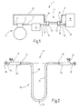
- Fig. 1 eine Kraftfahrzeug-Klimaanlage in schematischer Prinzipdarstellung,
- Fig. 2 einen inneren Wärmetauscher der Kraftfahrzeug-
Klimaanlage nach Figur 1, in Seitenansicht, - Fig. 3 ein für den
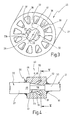
Wärmetauscher nach Figur 2 vorgesehenes Wärmetauscherrohr, in einer perspektivischen Schnittdarstellung, - Fig. 4 den
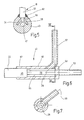
Wärmetauscher nach Figur 2, in einer ausschnittsweisen und teilweise aufgeschnittenen Darstellung, - Fig. 5 den
Wärmetauscher nach Figur 2, geschnitten entlang einer Linie V-V in Figur 4, - Fig. 6 eine alternative Ausführungsform eines Wärmetauschers mit Drallkammer-Anschlussstücken, in ausschnittsweiser und teilweise geschnittener Darstellung,
- Fig. 7 den
Wärmetauscher nach Figur 6, geschnitten entlang der Linie VII-VII inFigur 6, und - Fig. 8 eine alternative Ausführungsform eines Wärmetauscherrohrs, in schematisierter Schnittdarstellung, und
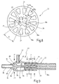
- Fig. 9 eine alternative Ausführungsform eines Wärmetauschers mit angepresstem Anschlussstücken, in ausschnittsweiser und teilweise geschnittener Darstellung.
- 1 is a motor vehicle air conditioning in a schematic diagram,
- 2 shows an internal heat exchanger of the motor vehicle air conditioning system according to FIG. 1, in side view,
- 3 is a provided for the heat exchanger of Figure 2 heat exchanger tube, in a perspective sectional view,
- 4 shows the heat exchanger of Figure 2, in a partial and partially cutaway view,
- 5 shows the heat exchanger according to FIG. 2, cut along a line VV in FIG. 4, FIG.
- 6 shows an alternative embodiment of a heat exchanger with swirl chamber connecting pieces, in partial and partially sectional representation,
- Fig. 7 shows the heat exchanger of Figure 6, taken along the line VII-VII in Figure 6, and
- Fig. 8 shows an alternative embodiment of a heat exchanger tube, in a schematic sectional view, and
- 9 shows an alternative embodiment of a heat exchanger with pressed-on connection pieces, in partial and partially sectional representation.
In Figur 1 ist eine Kältmaschine 1 für Kraftfahrzeuge veranschaulicht. Zu der Kältemaschine 1 gehört ein Kompressor 2, der bspw. von dem Motor des Kraftfahrzeugs angetrieben ist. Der Kompressor 2 weist einen Ausgang 3 und einen Eingang 4 auf. Während er an dem Eingang 4 gasförmiges Fluid ansaugt, gibt er an dem Ausgang 3 verdichtetes Fluid ab. Von dem Ausgang 3 führt eine Druckleitung 5 zu einem Kühler 6, in dem das verdichtete Wärmeträgerfluid (z.B. CO2 Propan, Butan, R134a oder Ammoniak) abkühlt und/oder kondensiert. Das abgekühlte und unter hohem Druck (z.B. zwischen 100 bar und 150 bar bei CO2) stehende Wärmeträgerfluid wird an einem Ausgang 7 des Kühlers 6 an eine weitere Druckleitung 8 abgegeben, die zu einem Hochdruckeingang 9 eines Wärmetauschers 11 führt. Dieser weist einen Hochdruckausgang 12 auf, an den über eine Druckleitung 14 ein Expansionsventil 15 angeschlossen ist. Dieses bewirkt eine Entspannung des Wärmeträgerfluids, das in einen Verdampfer 16 eingeleitet wird. Hier verdampft es unter Aufnahme von Umgebungswärme, bspw. zur Abkühlung von Luft in einer Klimaanlage. Aus dem Verdampfer 16 wird der entstehende kalte Dampf des Wärmeträgerfluids über eine Niederdruckleitung 17 zu einem Niederdruckeingang 18 des Wärmetauschers 11 geführt. Es durchströmt diesen im Gegenstrom zu dem über den Hochdruckeingang 9 zugeführten Fluid. Dabei tritt es in Wärmeaustausch mit diesem und wird an einem Niederdruckausgang 19 erwärmt abgegeben. Von diesem wird es über eine Niederdruckleitung 21 dem Eingang 4 des Kompressors 2 zugeführt.FIG. 1 illustrates a refrigerating
Der Wärmetauscher 11 ist in Figur 2 gesondert veranschaulicht. Er weist ein Wärmetauscherrohr 22 auf, das individuell gestaltet sein kann und im vorliegenden Ausführungsbeispiel U-förmig gebogen ist. Es weist zwei gerade, im Abstand parallel zueinander verlaufende Schenkel 23, 24 auf, die untereinander durch einen bogenförmigen Abschnitt 25 verbunden sind. Die Enden der beiden Schenkel 23, 24 sind jeweils voneinander weg gebogen und zueinander fluchtend, d.h. koaxial zu einer gemeinsamen Achse 26 angeordnet.The
Das Wärmetauscherrohr 22 ist ein im Strangpressverfahren hergestelltes mehrkammeriges Aluminiumprofil. Es ist in Figur 3 zu Veranschaulichung seines Querschnitts gesondert dargestellt. Das Wärmetauscherrohr 22 weist eine vorzugsweise zylindrische äußere Mantelfläche 27 auf, die koaxial zu einer Längsmittelachse 28 angeordnet ist. Ebenfalls koaxial zu der Längsmittelachse 28 ist ein Zentralkanal 29 vorgesehen, der einen von der Kreisform abweichenden Querschnitt aufweist. Im vorliegenden Ausführungsbeispiel, d.h. bei einer Klimaanlage mit CO2 als Kältemittel (Wärmeträgerfluid), wird ein Außendurchmesser des Zentralkanals 29 von 5mm bis 6mm als zweckmäßig angesehen. Dieser Durchmesser ist in Figur 3 durch eine gestrichelte Linie 31 angedeutet. Von diesem Durchmesser ausgehend ist der Zentralkanal 29 durch im Ausführungsbeispiel vier Vorsprünge 32 verengt, die einander paarweise gegenüberliegend angeordnet sind. Bedarfsweise können jedoch auch mehr (z.B. fünf oder sechs) oder weniger (z.B. lediglich zwei oder drei) Vorsprünge 32 vorgesehen sein.The
Die Vorsprünge 32 bilden Längsrippen 33, die sich parallel zu der Längsmittelachse 28 erstrecken. Die zu der Längsmittelachse 28 hinweisenden Enden der Rippen 33 sind gerundet, wobei der Rundungsradius etwa in der Größenordnung der Höhe jeder Rippe (gemessen von der gestrichelten Linie 31) liegt. Ist der Radius etwas kleiner, haben die Längsrippen 33 jeweils einen etwa dreieckigen Querschnitt mit einem vorzugsweise rechten Winkel zwischen den beiden die Rippe 33 begrenzenden Flanken 33a, 33b. Sind die Flanken 33a, 33b nicht eben sondern gerundet, ist der Winkel zwischen an die Flanken 33a, 33b gelegten Tangenten etwa 90°.The
Das Wärmetauscherrohr 22 ist einstückig ausgebildet und weist mehrere Außenkanäle 36 auf. In der Ausführungsform nach Figur 3 sind die Außenkanäle 36 untereinander gleich ausgebildet. Es sind wenigstens sieben, vorzugsweise aber mehr Außenkanäle 36 vorgesehen. Bevorzugt werden zwölf Außenkanäle mit, wie aus Figur 3 ersichtlich, etwa keilförmigem Querschnitt. Die Außenkanäle 36 sind untereinander durch Zwischenwände 37 getrennt, wobei der Winkel zwischen zwei Zwischenwänden 37 etwa 30° beträgt. Die Zwischenwände 37 erstrecken sich etwa parallel zu der Längsmittelachse 28 sowie radial zu dieser. Sie weisen eine sowohl in Längsrichtung als auch in Radialrichtung gleichbleibende Wandstärke auf. Diese beträgt im vorliegenden Ausführungsbeispiel etwa 1mm bis 1,5mm und ist kleiner als die mittlere Breite eines Außenkanals 36. Nach außen hin sind die Außenkanäle 36 durch einen Wandabschnitt 38 geschlossen, dessen Dicke etwa mit der Dicke einer Zwischenwand 37 übereinstimmt und etwa 1mm beträgt.The
Die Außenkanäle 36 sind äquidistant zueinander und auf einem zu der Längsmittelachse 28 koaxialen Kreis angeordnet. Ihr radial inneres Ende ist von der Linie 31 um ein Maß beabstandet, das größer ist, als die Dicke einer Zwischenwand. Im vorliegenden Fall beträgt der Abstand etwa 1,5mm. Dadurch wird eine ausreichende Wandstärke zwischen dem Zentralkanal 29 und den Außenkanälen 36 geschaffen, um eine hohe Druckfestigkeit des Zentralkanal 29 sicherzustellen.The
Während der Zentralkanal 29 etwa stern- oder kreuzförmig ausgebildet ist, sind die Außenkanäle 36 etwa keilförmig ausgebildet, wobei alle Kanäle 29, 36 jeweils gerundete Kanten aufweisen. Der Zentralkanal 29 berührt mit seinen Wandabschnitten, die den größten Durchmesser aufweisen, den durch die Linie 31 bezeichneten Kreis, während die Außenkanäle 36 mit ihren inneren Wandungsabschnitten einen durch die Linie 39 und mit ihren äußeren Wandungsabschnitten einen durch die Linie 41 bezeichneten Kreis berühren.While the
Das Wärmetauscherrohr 22 ist wesentlicher Bestandteil des druckfesten Wärmetauschers 11. Zu diesem gehören, wie aus Figur 2 ersichtlich, außerdem Anschlussstücke 42, 43, die an den beiden Enden 44, 45 des Wärmetauscherrohrs 22 befestigt sind und an denen der Hochdruckeingang 9, der Hochdruckausgang 12, der Niederdruckeingang 18 und der Niederdruckausgang 19 angeordnet sind. Die beiden Anschlussstücke 42, 43 sind untereinander vorzugsweise gleich ausgebildet. Die nachfolgende Beschreibung des Anschlussstücks 43 gilt somit entsprechend für das Anschlussstück 42.The
Wie aus Figur 4 ersichtlich, weist das Anschlussstück 43 einen etwa zylindrischen Grundkörper 46 auf, der zur Aufnahme des Endes 45 des Wärmetauscherrohrs 22 mit einer Öffnung 47 versehen ist. Die Öffnung 47 ist zunächst zylindrisch ausgebildet, mit einem Durchmesser der etwa mit dem Durchmesser der Mantelfläche 27 des Wärmetauscherrohrs 22 übereinstimmt oder geringfügig größer ist als dieser. Dieser zylindrische Abschnitt der Öffnung 47 geht bei einer Ringschulter 48 in einen konischen Abschnitt 49 über, in dem sich der Durchmesser der Öffnung 47 von dem Ende 45 weg verringert. An einer Übergangsstelle 51 geht die Öffnung 47 wiederum in einen zylindrischen Abschnitt 52 über. Zur Aufnahme eines entsprechenden, bspw. den Hochdruckausgang 12 bildenden Anschlussstücks 53, erweitert sich der zylindrische Abschnitt 52 dann nochmals auf einen etwas größeren Durchmesser.As can be seen from FIG. 4, the connecting
Die Öffnung 47 bildet mit ihrem konischen Abschnitt 49 eine Sammelkammer, in die ein oder mehrere, im vorliegenden Ausführungsbeispiel zwei einander diametral gegenüberliegende Kanäle 54, 55 münden. Wie insbesondere aus Figur 5 ersichtlich, liegen diese Kanäle 54, 55 einander gegenüber und münden an der konischen Wandung der Öffnung 47. Die Kanäle 54, 55 führen in einer radial angeordneten Seitenkammer 56 zusammen, an die ein z.B. dem Niederdruckeingang 18 bildendes rohrförmiges Anschlussstück 57 angeschlossen ist.The opening 47 forms with its conical portion 49 a collecting chamber into which one or more, in the present embodiment, two diametrically
Zum Anschluss des Endes 45 des Wärmetauscherrohrs 22 sind von einem kurzen Abschnitt seines Endes 45 der äußere Wandabschnitt 38 sowie die Zwischenwände 37 entfernt, so dass lediglich ein rohrförmiges, den Zentralkanal 29 umgebendes Stück 58 übrigbleibt. Dieses durchquert die Öffnung 47 und ragt in den Abschnitt 52 der Öffnung 47, wenn das Ende 45 in die Öffnung 47 eingesetzt ist. Dies ist in Figur 4 veranschaulicht. Außerdem ist aus Figur 4 ersichtlich, dass das Wärmetauscherrohr 22 mit dem Anschlussstück 43 bei einer entsprechenden Schweißnaht 59 verschweißt ist. Ebenso ist das Anschlussstück 53 mit dem Anschlussstück 43 über eine Schweißnaht 61 verschweißt. Das Anschlussstück 57 ist mit dem Anschlussstück 43, wie aus Figur 5 hervorgeht, über eine Schweißnaht 62 verschweißt.To connect the
Anstelle einer Schweißverbindung kann auch eine Lötverbindung oder bei ausreichender Dimensionierung eine Klebeverbindung vorgesehen werden. Das Stück 58 kann im Presssitz in dem Abschnitt 52 des Anschlussstücks 43 sitzen. Auf eine absolut fluiddichte Abdichtung kommt es auch hier an, weil auch geringfügigste Leckagen zwischen dem Zentralkanal 29 und den Außenkanälen 36 nicht zulässig sind. Falls dies nicht ausreicht, kann hier eine Löt- oder Schweißverbindung oder alternativ eine Klebeverbindung oder Pressverbindung vorgesehen werden und/oder ein Dichtungsmittel wie bspw. ein O-Ring eingesetzt werden.Instead of a welded joint, it is also possible to provide a soldered joint or, given sufficient dimensioning, an adhesive bond. The
Die insoweit beschriebene Kältemaschine 1 arbeitet wie folgt:The
In Betrieb verdichtet der Kompressor 2 aus dem Verdampfer 16 abgesaugten Dampf. Dieser wird über die Niederdruckleitung 17 dem Wärmetauscher 11 zugeführt. Hier gelangt er über den Niederdruckeingang 18 zunächst in die Kanäle 54, 55 zu gleichen Teilen. Diese führen den Dampf, der von der Öffnung 47 festgelegten konischen Kammer auf zwei einander diametral gegenüberliegenden Seiten zu, so dass diese gleichmäßig gefüllt wird. Der in die Kammer eingeführte Dampf kann sich somit gleichmäßig und mit gleichem Druck auf alle zwölf Außenkanäle 36 verteilen und den Wärmetauscher 11 durchströmen. An dem gegenüberliegenden Anschlussstück 42 tritt der in dem Wärmetauscher 11 erwärmte Dampf aus den Außenkanälen 36 aus und in eine entsprechende konische Kammer ein. Von dieser wird der erwärmte Dampf durch die beiden Kanäle 54, 55 wiederum dem Niederdruckausgang 19 zugeführt. Von hier aus gelangt der etwas erwärmte Dampf zu dem Kompressor 22. Nach Kompression und Abkühlung des Kältemittels wird dieses wiederum dem Hochdruckeingang 9 zugeführt. Dieser ist koaxial zu dem Zentralkanal 29 angeordnet. Das Kältemittel wird dem Zentralkanal somit unmittelbar zugeführt und zwar im Gegenstrom zu den Außenkanälen 36. Das den Zentralkanal 29 durchströmende Wärmeträgerfluid gibt hier einen Teil seiner noch vorhandenen Wärme an das Wärmetauscherrohr 22 ab, das die Wärme auf das im Gegenstrom durch die Außenkanäle 36 strömende kältere Fluid überträgt.In operation, the
Der beschriebene Wärmetauscher 11 ist kostengünstig herstellbar und bei geringem Materialeinsatz und Gewicht in hohem Maße druckfest und effektiv. Er eignet sich somit auf besonders gute Weise zum Einsatz in Kraftfahrzeugen.The described
Die Anschlussstücke 42, 43 haben jeweils die Aufgabe, die im Wesentlichen radial angeordneten Niederdruckanschlüsse (Niederdruckeingang 18, Niederdruckausgang 19) mit den Außenkanälen 36 so in Verbindung zu bringen, dass sich das ein- bzw. ausströmende Fluid gleichmäßig auf die Außenkanäle 36 verteilt. Außerdem müssen die im Wesentlichen axialen Anschlüsse (Hochdruckeingang 9, Hochdruckausgang 12) an den Zentralkanal 29 angeschlossen werden. Dazu ist auch das in Figur 6 stellvertretend für beide Anschlussstücke 42, 43 veranschaulichte Anschlussstück 43 geeignet. Es weist einen zylindrischen Grundkörper 65 auf, der eine zylindrische Kammer 66 umschließt. Diese weist an einem Ende eine Öffnung 67 mit vergrößertem Durchmesser und an dem gegenüberliegenden Ende eine Öffnung 68 mit kleinerem Durchmesser auf. Das Ende 45 des Wärmetauscherrohrs 22 ragt in die Öffnung 67 und ist in diesem abgedichtet fixiert. Dazu können Löt- oder Schweißverbindungen, Klebeverbindungen oder Presssitzverbindungen, unterstützt durch Dichtungsmittel wie bspw. O-Ringe, dienen.The connecting
Das Stück 58 des Wärmetauscherrohrs 22 erstreckt sich durch die Kammer 66 hindurch bis in die Öffnung 68. In dieser ist es abgedichtet gehalten, bspw. durch Löt-, Schweiß- oder Klebeverbindung oder im Presssitz. Im Anschluss an die Öffnung 68 ist außerdem das rohrförmige Anschlussstück 53 angeordnet.The
Während bei dem Ausführungsbeispiel der Anschlussstücke 42, 43 nach Figur 4 und 5 als mit zur gleichmäßigen Aufteilung des Wärmeträgerfluids auf die Außenkanäle 36 eine konische Kammer mit wenigstens zwei einander gegenüberliegenden Zuflüssen oder Abflüssen (Kanäle 54, 55) vorgesehen worden ist, dient bei der Ausführungsform nach den Figur 6 und 7 zur Vergleichmäßigung der Verteilung des Fluids eine Dreh- oder Wirbelbewegung des in der Kammer 6b befindlichen Fluids. Um diese zu induzieren, ist das rohrförmige Anschlussstück 57 so an die Kammer 66 angeschlossen, dass seine Rohrmittelachse 69 die Längsmittelachse 28 des Anschlussstücks 43 und des Wärmetauscherrohrs 22 nicht trifft. Der Abstand zwischen der Rohrmittelachse 69 und der Längsmittelachse 28 ist dabei aber kleiner als der Außendurchmesser des Stücks 58, um keine zu starke Wirbelbildung hervorzurufen. Außerdem ist das Anschlussstück 57 im Bereich seiner Mündung in die Kammer 66 etwas gegen die Radialrichtung geneigt; im Ausführungsbeispiel nach Figur 6 etwa um 40° bis 50°.While in the embodiment of the
Eine abgewandelte Ausführungsform des Wärmetauscherrohrs 22 ist in Figur 8 veranschaulicht. Wie bei dem vorstehend beschriebenen Ausführungsbeispiel schließen die Flanken 33a, 33b einen Winkel α von etwa 90° miteinander ein. Die Längsrippen 33 sind an ihrer der Längsmittelachse 28 zugewandten Seite mit einem Radius R1 gerundet, der etwa in der Größenordnung der Höhe jeder Längsrippe 33 liegt oder etwas größer als diese ist. Ebenso sind die Übergänge zwischen den Längsrippen 33 und den übrigen Bereichen der Wandung des Zentralkanals 29 mit einem Radius R2 gerundet, der jedoch vorzugsweise deutlich kleiner ist als der Radius R1. Der Winkel β zwischen benachbarten Zwischenwänden 37 beträgt einheitlich 30° und die Wandungsstärke wie eins der Zwischenwände 37 ist etwas größer (1,2mm) als die Wandungsstärke W2 der Außenwand (1mm).A modified embodiment of the
Abweichend von dem vorstehend beschriebenen Ausführungsbeispiel ist jedoch der Querschnitt der Außenkanäle 36 nicht vollständig einheitlich. Acht Außenkanäle 36a erstrecken sich bis zu dem durch die gestrichelte Linie 39 markierten Kreis, der konzentrisch zu der Längsmittelachse 28 angeordnet ist. Vier jeweils im Bereich einer Längsrippe 33 angeordnete Außenkanäle 36b erstrecken sich jedoch über diesen Kreis hinaus weiter nach innen. In diesem Bereich W3 wird eine Wandstärke erzielt, der etwa der Wandstärke W4 zwischen dem Zentralkanal 28 und den kleineren Außenkanälen 36a erreicht wird.Notwithstanding the embodiment described above, however, the cross section of the
In den Figuren 4 bis 7 ist der Anschluss des Wärmetauscherrohrs 22 schematisch veranschaulicht. Eine besonders vorteilhafte Ausführungsform des Wärmetauscherrohranschlusses ist dagegen in Fig. 9 veranschaulicht. Das Wärmetauscherrohr 22 ist mit seinem Ende 45 in einem rohrförmigen Fortsatz 81 des Anschlussstücks 43 gefasst, der abgedichtet auf der Mantelfläche 27 des Wärmetauscherrohrs sitzt. Zur mechanischen Sicherung dient eine Pressverbindung, die durch radiale Kompression des Fortsatzes 81 erreicht wird. Diese ist in Fig. 9 durch Pfeile F angedeutet.In the figures 4 to 7, the connection of the
In dem Fortsatz 81 sind ein oder mehrere Ringnuten 82 ausgebildet, die zur Aufnahme von jeweils vorzugsweise einem elastomeren O-Ring 83 dienen, der als Dichtungselement dient. O-Ringe werden wegen ihrer Elastizität als vorteilhaft angesehen (Vibrationsfestigkeit). Als Dichtungselemente kommen jedoch auch andere Elemente, wie z.B. Schneidringe in Frage, die sich in den Fortsatz 81 und in die Mantelfläche 27 einschneiden und eine rein metallische Abdichtung erbringen (Unempfindlichkeit gegen Fluide). Es ist auch möglich, Schneidringen und O-Ringe miteinander zu kombinieren, z.B. indem eine Ringnut 82 einen elastomeren O-Ring enthält und eine andere Ringnut mit einem metallischen Schneidring enthält.In the
An den Fortsatz 81 schließt sich ein Abschnitt 84 mit geringfügig vergrößertem Durchmesser bzw. nicht durch Radialkompression reduziertem Durchmesser an. Dieser Abschnitt umschließt eine Ein- oder Ausströmkammer 85 und ist endseitig durch eine Stirnwand 86 geschlossen. Die Wandung der Kammer 85 ist seitlich mit einer Öffnung 87 durchbrochen, in die das Anschlussrohr 57 eingelötet oder eingeschweißt ist.The
Die Stirnwand 86 ist ebenfalls mit einer Öffnung 88 versehen, in der ein Anschlusssockel 89 sitzt. Dieser weist einen zylindrischen Grundkörper auf, dessen Mantelfläche mit einer Ringnut 91 versehen ist. Die Stirnwand 86 greift mit der Berandung ihrer Öffnung 88 in die Ringnut. Dies wird erreicht, indem die Öffnung 88 zunächst mit einem Durchmesser hergestellt wird, der größer ist als der Durchmesser des Grundkörpers. In einem Radialkompressionsschritt wird die Öffnung 88 dann verkleinert, indem eine Kraft in Richtung der Pfeile F1 aufgeprägt wird. Zur Abdichtung und zusätzlichen Sicherung wird die Stirnwand 86 dann mit dem Anschlusssockel 89 verschweißt oder anderweitig stoffschlüssig verbunden.The
Von dem Anschlusssockel 89 erstreckt sich eine Kanüle 92 (rohrförmiger Fortsatz) in den Zentralkanal 29 hinein. Dazu sind zumindest in dem Bereich, über den sich die Kanüle 92 in den Zentralkanal 29 erstreck, die Rippen 33 entfernt - der Zentralkanal 29 ist hier zylindrisch. Die Kanüle 92 ist an ihrer Außenseite mit ringförmigen Metallrippen 93 versehen, die als Dichtungselemente dienen. Beim radialen Verpressen (Kräfte F) drücken sich diese Metallrippen in die Wandung des Zentralkanals und bewirken eine metallische Abdichtung. Die Metallrippen 93 können einstückig mit der Kanüle 92 ausgebildet sein. Alternativ können auch O-Ringe oder anderweitige Dichtungselemente vorgesehen werden.From the
Der Anschlusssockel 89 weist zum Anschluss des Zentralkanals 29 eine Anschlussöffnung 94 auf, die mit dem von der Kanüle 92 umschlossenen Kanal kommuniziert, dabei aber einen größeren Durchmesser aufweist. In diese Anschlussöffnung ist ein Rohrende 95 eingesteckt und mit dem Anschlusssockel 89 verschweißt oder alternativ anderweitig verbunden.The
Der Anschlusssockel 89 bildet mit dem äußeren Rohrteil (Abschnitt 84 und Fortsatz 81) ein zweiteiliges Anschlussstück. Der Anschlusssockel 89 weist in der Kammer 85 im Übergang zu der Kanüle 92 eine konkav geformte ringförmige Leitfläche 96 auf, die eine Strömung aus der Radialrichtung in die Axialrichtung (oder umgekehrt) umleitet. Diese Leitfläche reduziert Strömungsverluste und bewirkt in Verbindung mit der ringförmigen Kammer 85, deren Länge etwa so groß ist wie deren Durchmesser, eine gleichmäßige Verteilung der Strömung auf die Kanäle 36a oder eine gleichmäßige Fluidabnahme von diesen Kanälen 36a.The
Eine Klimaanlage für ein Kraftfahrzeug enthält einen Wärmetauscher 11 mit einem Wärmetauscherrohr 22, das einen profilierten Zentralkanal 29 und um diesen herum gruppierte Außenkanäle 36 aufweist. Dieses Wärmetauscherrohr 22 ist zum Aufbau von Gegenstromwärmetauschern geeignet. Das Wärmetauscherrohr 22 ist dazu auf entsprechende Länge abzuschneiden und mit entsprechenden Endstücken 42, 43 zu versehen. Derartige Wärmetauscher erweisen sich als leicht, druckfest und effektiv.An automotive air conditioning system includes a
Claims (24)
- Heat exchanger (11) with a heat exchanger tube (22),
with a central channel (29) having a closed wall from which several protrusions (31) extend into the central channel (29),
with a plurality of outer channels (36) disposed concentric to the central channel (29) and separated from each other by intermediate walls (37),
characterised in that
the heat exchanger tube (22) at both ends (44, 45) is connected to connector pieces (42, 43) which each have a collecting chamber (47, 66) in order to merge all outer channels (36) into one channel, and
that the connection pieces (42, 43) respectively have means for even division of a fluid flow to the outer channels (36) and for even merging of the fluid flow coming from the outer channels (36). - Heat exchanger according to claim 1, characterised in that the number of intermediate walls (37) of the heat exchanger tube (22) is greater than the number of protrusions (31).
- Heat exchanger according to claim 1, characterised in that the outer channels (36) of the heat exchanger tube (22) on their radial inner side each have a width which is less than their height measured in the radial direction.
- Heat exchanger according to claim 1, characterised in that the outer channels (36) of the heat exchanger tube (22) on their radial outer side each have a width which is less than the height measured in the radial direction.
- Heat exchanger according to claim 1, characterised in that the intermediate walls (37) of the heat exchanger tube (22) are formed with parallel sides.
- Heat exchanger according to claim 1, characterised in that all outer channels (36) of the heat exchanger tube (22) have matching cross-sections.
- Heat exchanger according to claim 1, characterised in that the outer channels (36a, 36b) of the heat exchanger tube (22) have at least two different cross-sections.
- Heat exchanger according to claim 1, characterised in that all intermediate walls (37) of the heat exchanger tube (22) have a uniform wall thickness.
- Heat exchanger according to claim 1, characterised in that between the central channel (29) of the heat exchanger tube (22) and the outer channels (36) is provided a wall thickness that is greater than the wall thickness of the intermediate walls (37).
- Heat exchanger according to claim 1, characterised in that between the central channel (29) of the heat exchanger tube (22) and the outer channels (36) of the heat exchanger tube (22) is provided a wall thickness which is greater than the wall thickness of wall areas (38) which close the outer channels (36) on the outside.
- Heat exchanger according to claim 1, characterised in that the outer channels (36) of the heat exchanger tube (22) have a wedge-shaped cross-section.
- Heat exchanger according to claim 1, characterised in that the central channel (29) of the heat exchanger tube (22) has a cruciform cross-section.
- Heat exchanger according to claim 1, characterised in that the protrusions (31) of the heat exchanger tube (22) have a triangular rounded cross-section.
- Heat exchanger according to claim 1, characterised in that the protrusions (31) of the heat exchanger tube (22) have sides which enclose a right angle (α) with each other.
- Heat exchanger according to claim 1, characterised in that the protrusions (31) of the heat exchanger tube (22) are formed as ribs (33).
- Heat exchanger according to claim 15, characterised in that the ribs (33) of the heat exchanger tube (22) are formed straight in the axial direction.
- Heat exchanger according to claim 1, characterised in that the heat exchanger tube (22) is formed as an aluminium extruded profile.
- Heat exchanger according to claim 1, characterised in that the means for even division or merging of the fluid flow is a diffuser chamber (47).
- Heat exchanger according to claim 1, characterised in that the means for even division or merging of the fluid flows is a swirl chamber (66).
- Heat exchanger according to claim 19, characterised in that the diffuser chamber is formed conical and has at least two supply and discharge channels (54, 55).
- Heat exchanger according to claim 19, characterised in that the swirl chamber (66) has a substantially cylindrical cross-section.
- Heat exchanger according to claim 19, characterised in that the swirl chamber has a supply or discharge connection (57) offset parallel to the radial direction and angled.
- Heat exchanger according to claim 1, characterised in that the connection pieces (42, 43) are formed the same at both ends (44, 45) of the heat exchanger tube.
- Air conditioning system (1) in particular for motor vehicles,
with a compressor (2) to provide compressed fluids to an outlet (3),
with a cooler (6) for cooling the compressed fluid that is connected via a line (5) to the compressor (2),
with an expansion valve (15) which via a high pressure line (14) receives cooled fluid from the condenser (6) and passes this to an evaporator (16),
with a return line (17, 21) via which fluid is returned from the evaporator (16) to the compressor (2), and
with a heat exchanger (11) according to any of claims 1 to 23, the central channel (29) of which is connected to the high pressure line (8, 14) and the outer channels (36) of which are connected to the return line (17, 21).
Priority Applications (1)
| Application Number | Priority Date | Filing Date | Title |
|---|---|---|---|
| SI200130717T SI1202016T1 (en) | 2000-10-25 | 2001-10-10 | Air-conditioning system with internal heat exchanger and heat exchanger tube for same |
Applications Claiming Priority (2)
| Application Number | Priority Date | Filing Date | Title |
|---|---|---|---|
| DE10053000 | 2000-10-25 | ||
| DE10053000A DE10053000A1 (en) | 2000-10-25 | 2000-10-25 | Air conditioning system with internal heat exchanger and heat exchanger tube for one |
Publications (3)
| Publication Number | Publication Date |
|---|---|
| EP1202016A2 EP1202016A2 (en) | 2002-05-02 |
| EP1202016A3 EP1202016A3 (en) | 2004-12-08 |
| EP1202016B1 true EP1202016B1 (en) | 2007-01-17 |
Family
ID=7661072
Family Applications (1)
| Application Number | Title | Priority Date | Filing Date |
|---|---|---|---|
| EP01124090A Expired - Lifetime EP1202016B1 (en) | 2000-10-25 | 2001-10-10 | Air-conditioning system with internal heat exchanger and heat exchanger tube for same |
Country Status (6)
| Country | Link |
|---|---|
| US (1) | US6883601B2 (en) |
| EP (1) | EP1202016B1 (en) |
| JP (1) | JP3947993B2 (en) |
| DE (2) | DE10053000A1 (en) |
| ES (1) | ES2278672T3 (en) |
| SI (1) | SI1202016T1 (en) |
Cited By (2)
| Publication number | Priority date | Publication date | Assignee | Title |
|---|---|---|---|---|
| DE102007007228A1 (en) * | 2007-02-14 | 2008-08-21 | Behr Kirchberg Gmbh | Method and device for separating semi-finished products for use in line-integrated heat exchangers |
| DE102007042841A1 (en) | 2007-09-10 | 2009-03-12 | Behr Gmbh & Co. Kg | Connection device for use in air conditioning system of motor vehicle, has coaxial pipe or pipe arrangement at end connected with connecting piece, and flexible hose connected with connecting piece by one of openings of connections |
Families Citing this family (45)
| Publication number | Priority date | Publication date | Assignee | Title |
|---|---|---|---|---|
| JP3676994B2 (en) * | 2001-09-05 | 2005-07-27 | 本田技研工業株式会社 | Hydraulic bulge forming method for aluminum hollow extrusions |
| DE10243726B4 (en) * | 2002-09-20 | 2008-03-27 | Erbslöh Aluminium Gmbh | Heat exchanger and method of making a heat exchanger and extruded composite profile for use in such a process |
| EP1540223A1 (en) | 2002-09-20 | 2005-06-15 | Erbslöh Aluminium GmbH | Heat exchanger, method for producing said heat exchanger and an extruded composite profile used for the production thereof |
| EP1433990A1 (en) * | 2002-12-26 | 2004-06-30 | Calsonic Kansei Corporation | Flexible hose |
| DE10303595B4 (en) * | 2003-01-30 | 2005-02-17 | Visteon Global Technologies, Inc., Dearborn | Multi-channel heat exchanger and connection unit |
| JP4196774B2 (en) * | 2003-07-29 | 2008-12-17 | 株式会社デンソー | Internal heat exchanger |
| DE102004003325A1 (en) * | 2004-01-22 | 2005-08-18 | Valeo Klimasysteme Gmbh | Coaxial heat exchanger, in particular, for a vehicle heating/ventilating and/or air-conditioning plant comprises at least one structure whose wall thickness with respect to at least one of its other structures is reduced |
| DE102005052974B4 (en) * | 2004-11-09 | 2013-03-21 | Denso Corporation | Double walled pipe |
| WO2006073134A1 (en) * | 2005-01-07 | 2006-07-13 | Valeo Thermal Systems Japan Corporation | Tube body and heat exchanger formed by using the same |
| US7565808B2 (en) * | 2005-01-13 | 2009-07-28 | Greencentaire, Llc | Refrigerator |
| JP4387974B2 (en) * | 2005-04-25 | 2009-12-24 | パナソニック株式会社 | Refrigeration cycle equipment |
| SI1888294T1 (en) * | 2005-05-26 | 2014-08-29 | Alfa Laval Corporate Ab | A method of brazing articles of stainless steel |
| WO2007022777A1 (en) * | 2005-08-25 | 2007-03-01 | Knudsen Køling A/S | A heat exchanger |
| DE102005043506A1 (en) | 2005-09-12 | 2007-03-15 | Behr Gmbh & Co. Kg | Connection arrangement, in particular for a heat exchanger |
| DE102005056650A1 (en) * | 2005-11-25 | 2007-05-31 | Behr Gmbh & Co. Kg | Coaxial tube or tube-in-tube arrangement, in particular for a heat exchanger |
| DE102005056651A1 (en) | 2005-11-25 | 2007-05-31 | Behr Gmbh & Co. Kg | Coaxial tube or tube-in-tube arrangement, in particular for a heat exchanger |
| DE102006017816B4 (en) * | 2006-04-13 | 2008-04-24 | Eaton Fluid Power Gmbh | Inner chiller heat exchanger |
| JP4897423B2 (en) * | 2006-10-06 | 2012-03-14 | ホシザキ電機株式会社 | Ice making drum of drum type ice making machine |
| DE102007054732A1 (en) | 2006-11-14 | 2008-07-03 | Behr Kirchberg Gmbh | Connection arrangement for use in motor vehicle air conditioner, particularly for heat exchanger, has pipe like projection in annular groove which shuffle in inner region of internal pipe of coaxial pipe or pipe arrangement |
| EP1923655A3 (en) | 2006-11-14 | 2013-04-10 | Behr Kirchberg Gmbh | Connection assembly, especially for a heat exchanger |
| JP2008207630A (en) * | 2007-02-23 | 2008-09-11 | Tgk Co Ltd | Internal heat exchanger for automotive air conditioner |
| DE102007015186A1 (en) * | 2007-03-29 | 2008-10-02 | Valeo Klimasysteme Gmbh | Internal heat exchanger for an air conditioner |
| FR2915561B1 (en) * | 2007-04-27 | 2009-06-26 | Hutchinson Sa | INTERNAL THERMAL EXCHANGER FOR A MOTOR VEHICLE AIR CONDITIONING CIRCUIT, ONE SUCH CIRCUIT AND METHOD FOR CONNECTING TWO CONNECTORS TO THIS EXCHANGER |
| US7726135B2 (en) | 2007-06-06 | 2010-06-01 | Greencentaire, Llc | Energy transfer apparatus and methods |
| JP2009162395A (en) * | 2007-12-28 | 2009-07-23 | Showa Denko Kk | Double-wall-tube heat exchanger |
| US20090200005A1 (en) * | 2008-02-09 | 2009-08-13 | Sullivan Shaun E | Energy transfer tube apparatus, systems, and methods |
| DE102008022933B3 (en) * | 2008-05-09 | 2009-12-31 | Erbslöh Aluminium Gmbh | Coaxial molding e.g. for air-conditioning unit, has convexly curved front face of coaxial molding |
| EP2116803B1 (en) | 2008-05-09 | 2016-03-16 | Erbslöh Aluminium GmbH | Coaxial profile and method for manufacturing the same |
| DE202008006379U1 (en) | 2008-05-09 | 2008-07-17 | Erbslöh Aluminium Gmbh | Koaxialprofil |
| DE102009028487A1 (en) * | 2008-08-12 | 2010-02-25 | Visteon Global Technologies, Inc., Van Buren Township | Device for cooling a gas stream |
| IT1392549B1 (en) * | 2008-11-24 | 2012-03-09 | Dytech Dynamic Fluid Tech Spa | HEAT EXCHANGER FOR A CONDITIONED AIR CONDITIONER OF A MOTOR VEHICLE PROVIDED WITH A PERFECTED CONNECTOR |
| DE102009044119A1 (en) | 2009-09-28 | 2011-03-31 | Contitech Kühner Gmbh & Cie. Kg | Inner heat exchanger, in particular for motor vehicle air conditioners |
| FR2953917B1 (en) * | 2009-12-10 | 2012-01-20 | Hutchinson | INTERNAL THERMAL EXCHANGER FOR AIR CONDITIONING CIRCUIT OF MOTOR VEHICLE AND SUCH CIRCUIT |
| DE102010034112A1 (en) * | 2010-08-12 | 2012-02-16 | Gm Global Technology Operations Llc (N.D.Ges.D. Staates Delaware) | Internal heat exchanger for a motor vehicle air conditioning system |
| DE102010037445A1 (en) | 2010-09-10 | 2012-03-15 | Contitech Kühner Gmbh & Cie. Kg | Air conditioner for use in motor car, has expansion valve that is integrated with connecting portion which is arranged at end of heat exchanger tube with respect to flow direction of vaporizer |
| JP5655477B2 (en) * | 2010-09-30 | 2015-01-21 | ダイキン工業株式会社 | Extruded tube, heat exchanger using the extruded tube, and refrigeration apparatus using the heat exchanger |
| US20130167570A1 (en) * | 2011-12-30 | 2013-07-04 | Jose Bouloy | Conduit for using only at one end of, and for mildly defrosting, an evaporator without causing excessive heat to affect the evaporator or occupants in proximity to the evaporator |
| FR2995674B1 (en) * | 2012-09-18 | 2017-10-20 | Dcns | HEAT EXCHANGER WITH TUBULAR THERMAL EXCHANGE TUBULAR STRUCTURE |
| WO2014054117A1 (en) * | 2012-10-02 | 2014-04-10 | 三菱電機株式会社 | Double-tube heat exchanger and refrigerating cycle device |
| CN102897000B (en) * | 2012-11-07 | 2016-01-27 | 奇瑞汽车股份有限公司 | A kind of automotive air-conditioning system and automobile |
| CN103542643B (en) * | 2013-10-21 | 2015-08-19 | 江苏超力电器有限公司 | A kind of auxiliary condenser of automotive air conditioner |
| DE102013020469A1 (en) * | 2013-12-06 | 2015-06-11 | Webasto SE | Heat exchanger and method for producing a heat exchanger |
| IT201700046660A1 (en) * | 2017-04-28 | 2018-10-28 | Milano Politecnico | LUBRICATED BEARING FOR ROTATING MACHINES |
| US11002386B2 (en) | 2019-01-17 | 2021-05-11 | Fmc Technologies, Inc. | Low erosion fluid conduit with sharp section geometry |
| DE102021214149A1 (en) * | 2021-12-10 | 2023-06-15 | Contitech Techno-Chemie Gmbh | Tube-in-tube heat exchanger |
Family Cites Families (17)
| Publication number | Priority date | Publication date | Assignee | Title |
|---|---|---|---|---|
| FR1259542A (en) * | 1960-03-18 | 1961-04-28 | Alsthom Cgee | New spacers arrangements for heat exchangers |
| BE655554A (en) * | 1963-11-19 | |||
| US3887004A (en) * | 1972-06-19 | 1975-06-03 | Hayden Trans Cooler Inc | Heat exchange apparatus |
| US4256170A (en) * | 1979-07-20 | 1981-03-17 | Crump Robert F | Heat exchanger |
| US4345644A (en) * | 1980-11-03 | 1982-08-24 | Dankowski Detlef B | Oil cooler |
| FR2545594A1 (en) * | 1983-05-05 | 1984-11-09 | Scoma Energie | Heat exchanger |
| EP0138677A3 (en) * | 1983-09-21 | 1985-05-22 | Office National d'Etudes et de Recherches Aérospatiales (O.N.E.R.A.) | Heat-exchanger tubes, heat-exchangers provided therewith and gas-turbine plants comprising such a heat-exchanger |
| EP0218930A1 (en) * | 1985-09-14 | 1987-04-22 | Norsk Hydro A/S | Cooler |
| DE3605244A1 (en) * | 1986-02-19 | 1987-08-20 | Norsk Hydro As | Cooler, for example oil cooler |
| GB8909529D0 (en) * | 1989-04-26 | 1989-06-14 | Specialist Heat Exchangers Lim | Heat exchanger |
| JPH04132446U (en) * | 1991-05-29 | 1992-12-08 | 本田技研工業株式会社 | automotive gasoline cooling system |
| US5326252A (en) * | 1991-09-04 | 1994-07-05 | Thomas Tonon | Catalytic combustion |
| US5375654A (en) * | 1993-11-16 | 1994-12-27 | Fr Mfg. Corporation | Turbulating heat exchange tube and system |
| DE9405062U1 (en) * | 1994-03-24 | 1994-05-26 | Hoval Interliz Ag | Heat exchanger tube for boilers |
| JPH10339588A (en) * | 1997-06-06 | 1998-12-22 | Denso Corp | Heat exchanger and manufacture thereof |
| DE19903833A1 (en) * | 1999-02-01 | 2000-08-03 | Behr Gmbh & Co | Integrated collector heat exchanger assembly |
| DE19944951B4 (en) * | 1999-09-20 | 2010-06-10 | Behr Gmbh & Co. Kg | Air conditioning with internal heat exchanger |
-
2000
- 2000-10-25 DE DE10053000A patent/DE10053000A1/en not_active Withdrawn
-
2001
- 2001-10-10 DE DE50111891T patent/DE50111891D1/en not_active Expired - Lifetime
- 2001-10-10 EP EP01124090A patent/EP1202016B1/en not_active Expired - Lifetime
- 2001-10-10 SI SI200130717T patent/SI1202016T1/en unknown
- 2001-10-10 ES ES01124090T patent/ES2278672T3/en not_active Expired - Lifetime
- 2001-10-23 US US10/002,670 patent/US6883601B2/en not_active Expired - Lifetime
- 2001-10-24 JP JP2001326767A patent/JP3947993B2/en not_active Expired - Fee Related
Cited By (2)
| Publication number | Priority date | Publication date | Assignee | Title |
|---|---|---|---|---|
| DE102007007228A1 (en) * | 2007-02-14 | 2008-08-21 | Behr Kirchberg Gmbh | Method and device for separating semi-finished products for use in line-integrated heat exchangers |
| DE102007042841A1 (en) | 2007-09-10 | 2009-03-12 | Behr Gmbh & Co. Kg | Connection device for use in air conditioning system of motor vehicle, has coaxial pipe or pipe arrangement at end connected with connecting piece, and flexible hose connected with connecting piece by one of openings of connections |
Also Published As
| Publication number | Publication date |
|---|---|
| US6883601B2 (en) | 2005-04-26 |
| JP3947993B2 (en) | 2007-07-25 |
| EP1202016A2 (en) | 2002-05-02 |
| SI1202016T1 (en) | 2007-06-30 |
| ES2278672T3 (en) | 2007-08-16 |
| DE50111891D1 (en) | 2007-03-08 |
| US20020046830A1 (en) | 2002-04-25 |
| EP1202016A3 (en) | 2004-12-08 |
| JP2002181466A (en) | 2002-06-26 |
| DE10053000A1 (en) | 2002-05-08 |
Similar Documents
| Publication | Publication Date | Title |
|---|---|---|
| EP1202016B1 (en) | Air-conditioning system with internal heat exchanger and heat exchanger tube for same | |
| DE102006017816B4 (en) | Inner chiller heat exchanger | |
| DE10303595B4 (en) | Multi-channel heat exchanger and connection unit | |
| EP0845647B1 (en) | Flat tube heat exchanger with twisted tube ends | |
| DE102010025400A1 (en) | Double-wall heat exchanger | |
| WO2003054465A1 (en) | Device for exchanging heat | |
| DE60110296T2 (en) | Connection for double-walled pipes | |
| DE102011014352B4 (en) | ejector | |
| DE102005052973A1 (en) | Double-walled pipe, method of manufacture therefor and cooling circuit device provided therewith | |
| DE112006001982T5 (en) | heat exchangers | |
| DE102009049234A1 (en) | Pipe connection for use in connecting structure for double pipe, is connected with heat exchanging pipe, which has pipe section through which fluid flows, and has other pipe section, through which other fluid flows | |
| DE102013217287A1 (en) | Internal heat exchanger for refrigerant circuit for air conditioning system for motor car, has refrigerant-carrying tubes for transferring refrigerant heat from high pressure side to low pressure side, and are placed one above other | |
| DE102016100192B4 (en) | Device for heat transfer | |
| DE10217581A1 (en) | Heat exchanger collector construction | |
| EP2612095B1 (en) | Coolant condenser assembly | |
| EP1439367B1 (en) | Heat exchanger comprising a connector joined to the header | |
| DE10346141B4 (en) | heat exchanger unit | |
| DE102004002252A1 (en) | Heat exchanger for vehicles | |
| DE102006032570A1 (en) | Heat exchanger unit for air conditioning system of motor vehicle, has internal heat exchanger directly connected or soldered with heat exchanger over connecting cable for formation of structural unit | |
| DE102004033099A1 (en) | Heat exchanger for evaporation and gas cooling has first collecting tank with flow dividing element | |
| DE102012022363A1 (en) | Internal heat exchanger for a motor vehicle air conditioning system | |
| EP1795846A1 (en) | Heat exchanger with a plurality of tube elements | |
| EP1734324A2 (en) | Variable internal heat exchanger | |
| EP3009780B1 (en) | Heat exchanger | |
| DE10333464A1 (en) | Device for exchange of heat for especially air conditioning systems in motor vehicles has at least one of flow connecting sections of throughflow unit twisted at least one |
Legal Events
| Date | Code | Title | Description |
|---|---|---|---|
| PUAI | Public reference made under article 153(3) epc to a published international application that has entered the european phase |
Free format text: ORIGINAL CODE: 0009012 |
|
| AK | Designated contracting states |
Kind code of ref document: A2 Designated state(s): AT BE CH CY DE DK ES FI FR GB GR IE IT LI LU MC NL PT SE TR |
|
| AX | Request for extension of the european patent |
Free format text: AL;LT;LV;MK;RO;SI |
|
| PUAL | Search report despatched |
Free format text: ORIGINAL CODE: 0009013 |
|
| AK | Designated contracting states |
Kind code of ref document: A3 Designated state(s): AT BE CH CY DE DK ES FI FR GB GR IE IT LI LU MC NL PT SE TR |
|
| AX | Request for extension of the european patent |
Extension state: AL LT LV MK RO SI |
|
| 17P | Request for examination filed |
Effective date: 20050602 |
|
| AKX | Designation fees paid |
Designated state(s): DE ES FR GB IT SE |
|
| AXX | Extension fees paid |
Extension state: RO Payment date: 20050602 Extension state: SI Payment date: 20050602 |
|
| GRAP | Despatch of communication of intention to grant a patent |
Free format text: ORIGINAL CODE: EPIDOSNIGR1 |
|
| GRAS | Grant fee paid |
Free format text: ORIGINAL CODE: EPIDOSNIGR3 |
|
| GRAA | (expected) grant |
Free format text: ORIGINAL CODE: 0009210 |
|
| AK | Designated contracting states |
Kind code of ref document: B1 Designated state(s): DE ES FR GB IT SE |
|
| AX | Request for extension of the european patent |
Extension state: RO SI |
|
| REG | Reference to a national code |
Ref country code: GB Ref legal event code: FG4D Free format text: NOT ENGLISH |
|
| GBT | Gb: translation of ep patent filed (gb section 77(6)(a)/1977) |
Effective date: 20070202 |
|
| REF | Corresponds to: |
Ref document number: 50111891 Country of ref document: DE Date of ref document: 20070308 Kind code of ref document: P |
|
| REG | Reference to a national code |
Ref country code: SE Ref legal event code: TRGR |
|
| ET | Fr: translation filed | ||
| REG | Reference to a national code |
Ref country code: ES Ref legal event code: FG2A Ref document number: 2278672 Country of ref document: ES Kind code of ref document: T3 |
|
| PLBE | No opposition filed within time limit |
Free format text: ORIGINAL CODE: 0009261 |
|
| STAA | Information on the status of an ep patent application or granted ep patent |
Free format text: STATUS: NO OPPOSITION FILED WITHIN TIME LIMIT |
|
| 26N | No opposition filed |
Effective date: 20071018 |
|
| PGFP | Annual fee paid to national office [announced via postgrant information from national office to epo] |
Ref country code: SE Payment date: 20141007 Year of fee payment: 14 Ref country code: ES Payment date: 20141016 Year of fee payment: 14 |
|
| PGFP | Annual fee paid to national office [announced via postgrant information from national office to epo] |
Ref country code: IT Payment date: 20141015 Year of fee payment: 14 |
|
| REG | Reference to a national code |
Ref country code: SE Ref legal event code: EUG |
|
| PG25 | Lapsed in a contracting state [announced via postgrant information from national office to epo] |
Ref country code: IT Free format text: LAPSE BECAUSE OF NON-PAYMENT OF DUE FEES Effective date: 20151010 |
|
| REG | Reference to a national code |
Ref country code: SI Ref legal event code: KO00 Effective date: 20160630 |
|
| PG25 | Lapsed in a contracting state [announced via postgrant information from national office to epo] |
Ref country code: SE Free format text: LAPSE BECAUSE OF NON-PAYMENT OF DUE FEES Effective date: 20151011 |
|
| REG | Reference to a national code |
Ref country code: FR Ref legal event code: PLFP Year of fee payment: 16 |
|
| PGFP | Annual fee paid to national office [announced via postgrant information from national office to epo] |
Ref country code: GB Payment date: 20160926 Year of fee payment: 16 |
|
| REG | Reference to a national code |
Ref country code: ES Ref legal event code: FD2A Effective date: 20161125 |
|
| PGFP | Annual fee paid to national office [announced via postgrant information from national office to epo] |
Ref country code: FR Payment date: 20160926 Year of fee payment: 16 |
|
| PGFP | Annual fee paid to national office [announced via postgrant information from national office to epo] |
Ref country code: DE Payment date: 20161031 Year of fee payment: 16 |
|
| PG25 | Lapsed in a contracting state [announced via postgrant information from national office to epo] |
Ref country code: ES Free format text: LAPSE BECAUSE OF NON-PAYMENT OF DUE FEES Effective date: 20151011 |
|
| REG | Reference to a national code |
Ref country code: DE Ref legal event code: R119 Ref document number: 50111891 Country of ref document: DE |
|
| GBPC | Gb: european patent ceased through non-payment of renewal fee |
Effective date: 20171010 |
|
| REG | Reference to a national code |
Ref country code: FR Ref legal event code: ST Effective date: 20180629 |
|
| PG25 | Lapsed in a contracting state [announced via postgrant information from national office to epo] |
Ref country code: DE Free format text: LAPSE BECAUSE OF NON-PAYMENT OF DUE FEES Effective date: 20180501 Ref country code: GB Free format text: LAPSE BECAUSE OF NON-PAYMENT OF DUE FEES Effective date: 20171010 |
|
| PG25 | Lapsed in a contracting state [announced via postgrant information from national office to epo] |
Ref country code: FR Free format text: LAPSE BECAUSE OF NON-PAYMENT OF DUE FEES Effective date: 20171031 |