EP1201878B1 - Bladed rotor - Google Patents
Bladed rotor Download PDFInfo
- Publication number
- EP1201878B1 EP1201878B1 EP01307084A EP01307084A EP1201878B1 EP 1201878 B1 EP1201878 B1 EP 1201878B1 EP 01307084 A EP01307084 A EP 01307084A EP 01307084 A EP01307084 A EP 01307084A EP 1201878 B1 EP1201878 B1 EP 1201878B1
- Authority
- EP
- European Patent Office
- Prior art keywords
- blades
- airfoils
- row
- blisk
- splitter
- Prior art date
- Legal status (The legal status is an assumption and is not a legal conclusion. Google has not performed a legal analysis and makes no representation as to the accuracy of the status listed.)
- Expired - Lifetime
Links
Images
Classifications
-
- F—MECHANICAL ENGINEERING; LIGHTING; HEATING; WEAPONS; BLASTING
- F02—COMBUSTION ENGINES; HOT-GAS OR COMBUSTION-PRODUCT ENGINE PLANTS
- F02K—JET-PROPULSION PLANTS
- F02K3/00—Plants including a gas turbine driving a compressor or a ducted fan
- F02K3/02—Plants including a gas turbine driving a compressor or a ducted fan in which part of the working fluid by-passes the turbine and combustion chamber
- F02K3/04—Plants including a gas turbine driving a compressor or a ducted fan in which part of the working fluid by-passes the turbine and combustion chamber the plant including ducted fans, i.e. fans with high volume, low pressure outputs, for augmenting the jet thrust, e.g. of double-flow type
- F02K3/075—Plants including a gas turbine driving a compressor or a ducted fan in which part of the working fluid by-passes the turbine and combustion chamber the plant including ducted fans, i.e. fans with high volume, low pressure outputs, for augmenting the jet thrust, e.g. of double-flow type controlling flow ratio between flows
-
- F—MECHANICAL ENGINEERING; LIGHTING; HEATING; WEAPONS; BLASTING
- F01—MACHINES OR ENGINES IN GENERAL; ENGINE PLANTS IN GENERAL; STEAM ENGINES
- F01D—NON-POSITIVE DISPLACEMENT MACHINES OR ENGINES, e.g. STEAM TURBINES
- F01D5/00—Blades; Blade-carrying members; Heating, heat-insulating, cooling or antivibration means on the blades or the members
- F01D5/02—Blade-carrying members, e.g. rotors
- F01D5/022—Blade-carrying members, e.g. rotors with concentric rows of axial blades
-
- F—MECHANICAL ENGINEERING; LIGHTING; HEATING; WEAPONS; BLASTING
- F01—MACHINES OR ENGINES IN GENERAL; ENGINE PLANTS IN GENERAL; STEAM ENGINES
- F01D—NON-POSITIVE DISPLACEMENT MACHINES OR ENGINES, e.g. STEAM TURBINES
- F01D5/00—Blades; Blade-carrying members; Heating, heat-insulating, cooling or antivibration means on the blades or the members
- F01D5/34—Rotor-blade aggregates of unitary construction, e.g. formed of sheet laminae
Definitions
- the present invention relates generally to integrally formed bladed disks or "blisks" for turbine engines, and more particularly to a blisk having an integral splitter.
- a conventional gas turbine engine includes a high pressure compressor for compressing air traveling through the engine, a combustor downstream from the compressor for heating the compressed air, and a high pressure turbine downstream from the combustor for driving the high pressure compressor.
- One type of engine known as a bypass turbofan engine, also has a low pressure turbine downstream from the high pressure turbine for driving a fan upstream from the high pressure compressor.
- the first stage of the high pressure compressor is a core driven fan stage.
- the flowpath of the variable cycle engine is split at the core driven fan stage so it has concentric inner and outer ducts. The amount of air passing through the outer duct can be adjusted to change the thrust and fuel consumption of the engine.
- a core driven fan stage includes inner and outer airfoils positioned in the inner and outer ducts, respectively.
- a generally cylindrical splitter positioned between the inner and outer airfoils forms part of the inner flowpath surface of the outer duct and part of the outer flowpath surface of the inner duct.
- Some prior art core driven fans are formed from a single piece of material so the inner and outer airfoils, the splitter and a disk are integral. Such an integrally bladed disk is commonly referred to as a "blisk".
- each outer airfoil of the prior art blisks has a midspan chord length which is almost as long as (i.e., greater than 80 percent of) the midspan chord length of the inner airfoils.
- the midspan chord length is a straight line distance measured from a point at a leading edge of the airfoil halfway along its span (i.e., radial height) to a point at a trailing edge of the airfoil halfway along its span.
- US-A-5,562,419 also describes blisks for turbine engines with inner and outer rows of blades, generally in accordance with the preamble of claim 1 hereof.
- US-A-1,263,473 discloses a turbine disc having inner and outer rows of blades, with more blades in the outer row than in the inner row.
- the blisk includes an annular disk having a hub surrounding a central opening, a web extending generally radially outward from the hub and a rim surrounding the web.
- the blisk comprises an inner row of blades including a plurality of circumferentially spaced airfoils integrally formed with the disk. Each of the airfoils of the inner row of blades extends generally radially outward from a root positioned adjacent the rim of the disk to a tip opposite the root.
- the blisk includes an annular splitter integrally formed with the inner row of blades and surrounding the tips of the plurality of airfoils thereof.
- the splitter has an inner surface facing the tips of the plurality of airfoils of the inner row of blades and an outer surface opposite the inner surface.
- the blisk includes an outer row of blades including a plurality of circumferentially spaced airfoils integrally formed with the splitter.
- Each of the airfoils of the outer row of blades extends generally radially outward from a root positioned adjacent the outer surface of the splitter to a tip opposite the root.
- Each airfoil in the outer row of blades has a midspan chord length less than about 75 percent of a midspan chord length of the airfoils in the inner row of blades.
- a variable cycle gas turbine engine (partially shown) is designated in its entirety by the reference number 10.
- the engine 10 has a stator (generally designated by 12) and a high pressure or core rotor (generally designated by 14) rotatably mounted on the stator.
- the core rotor 14 includes an integrally bladed disk or "blisk”, generally designated by 20, which is the subject of the present invention.
- the stator 12 includes a frame, generally designated by 30, upstream from the blisk 20.
- the frame 30 includes an outer duct, generally designated by 32, defining an outer flowpath passageway 34 and an inner duct, generally designated by 36, defining an inner flowpath passageway 38.
- a plurality of circumferentially spaced outer variable pitch stator vanes 40 and a plurality of circumferentially spaced inner variable pitch stator vanes 42 are pivotally mounted in the outer flowpath passageway 34 and the inner flowpath passageway 38, respectively, for directing flow upstream from the blisk 20.
- a plurality of circumferentially spaced outer stationary stator vanes 44 is mounted downstream from the blisk for directing flow through the outer passageway 34, and a plurality of circumferentially spaced inner variable pitch stator vanes 46 is pivotally mounted downstream from the blisk 20 for directing flow through the inner passageway 38.
- the amount of air passing through the outer passageway 34 can be adjusted to change the thrust and fuel consumption of the engine 10.
- the features of the stator 12 are conventional, they will not be described in further detail.
- the blisk 20 includes an annular disk, generally designated by 60, having a hub 62 surrounding a central opening 64, a web 66 extending generally radially outward from the hub and a rim 68 surrounding the web.
- Each of the airfoils 72 of the inner row of blades 70 extends generally radially outward from a root 74 positioned adjacent the rim 68 of the disk 60 to a tip 76 opposite the root.
- the blisk 20 also includes an annular splitter, generally designated by 80, integrally formed with the inner row of blades 70 and surrounding the tips 76 of the airfoils 72.
- the splitter 80 has an inner surface 82 facing inward toward the tips 76 of the airfoils 72 of the inner row of blades 70 and an outer surface 84 opposite the inner surface.
- An outer row of blades 90 including a plurality of circumferentially spaced airfoils 92 is integrally formed with the splitter 80.
- Each of the airfoils 92 of the outer row of blades 90 extends generally radially outward from a root 94 positioned adjacent the outer surface 84 of the splitter 80 to a tip 96 opposite the root.
- the blisk 20 also includes an arm 98 which extends rearward to a flange 100 configured for connecting the blisk to a shaft 102 which extends axially through the engine 10 to the high pressure turbine (not shown).
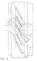
- FIG. 3 and 4 there are more airfoils 92 in the outer row of blades 90 than there are airfoils 72 in the inner row of blades 70. In one embodiment, there are twice as many airfoils 92 in the outer row of blades 90 as there are in the inner row of blades 70. In the illustrated embodiment, half of the airfoils 92 in the outer row of blades 90 are positioned directly radially outboard from the airfoils 72 in the inner row of blades 70, and the other half of the airfoils in the outer row of blades are positioned halfway between the first half of the airfoils. As will be appreciated by those skilled in the art, this configuration minimizes stress in the splitter 80 and maximizes fatigue life.
- each airfoil 92 in the outer row of blades 90 has a midspan chord length 110 less than about 75 percent of a midspan chord length 112 of the airfoils 72 in the inner row of blades 70.
- the midspan chord length 110 of the outer airfoils 92 is less than about 60 percent of the midspan chord length 112 of the inner airfoils 72.
- the midspan chord length 110 of the outer airfoils 92 is about 54 percent of the midspan chord length 112 of the inner airfoils 72.
- the fatigue life of the airfoils is improved by decreasing their peak stresses.
- increasing the number of outer airfoils provides increased tip airfoil solidity which may provide increased performance relative to a blisk having an equal number of inner and outer airfoils.
- the splitter 80 has a thickness 120 at a leading edge 122, a thickness 124 at a trailing edge 126 and a thickness 128 halfway between the leading and trailing edges.
- the thicknesses 120, 124 at the leading and trailing edges 122, 126, respectively are thinner than the thickness 128 of the splitter 80 immediately inboard from the outer row of blades 90.
- the thickness 128 of the splitter 80 inboard from the blades 90 can be optimized to obtain a desired fatigue life.
- the blisk 20 may be made using other methods without departing from the scope of the present invention, in one embodiment the blisk is formed from a single piece of material (e.g., by milling on a numerically controlled machine) so that the inner and outer airfoils, the splitter and a disk are integral. Further, the blisk 20 may be made of any conventional material used to manufacture gas turbine engine rotor components (e.g., a titanium or nickel base alloy) without departing from the scope of the present invention.
- gas turbine engine rotor components e.g., a titanium or nickel base alloy
- blisk 20 described above is used in a compressor section of the engine as a core driven fan stage, those skilled in the art will appreciate that the present invention may also be applied to other portions of a gas turbine engine 10 such as in the fan section or the turbine section.
Description
- The present invention relates generally to integrally formed bladed disks or "blisks" for turbine engines, and more particularly to a blisk having an integral splitter.
- A conventional gas turbine engine includes a high pressure compressor for compressing air traveling through the engine, a combustor downstream from the compressor for heating the compressed air, and a high pressure turbine downstream from the combustor for driving the high pressure compressor. One type of engine, known as a bypass turbofan engine, also has a low pressure turbine downstream from the high pressure turbine for driving a fan upstream from the high pressure compressor. In a variable cycle engine, the first stage of the high pressure compressor is a core driven fan stage. The flowpath of the variable cycle engine is split at the core driven fan stage so it has concentric inner and outer ducts. The amount of air passing through the outer duct can be adjusted to change the thrust and fuel consumption of the engine.
- As disclosed in U.S. Patent No. 5,988,980, a core driven fan stage includes inner and outer airfoils positioned in the inner and outer ducts, respectively. A generally cylindrical splitter positioned between the inner and outer airfoils forms part of the inner flowpath surface of the outer duct and part of the outer flowpath surface of the inner duct. Some prior art core driven fans are formed from a single piece of material so the inner and outer airfoils, the splitter and a disk are integral. Such an integrally bladed disk is commonly referred to as a "blisk".
- In the past, core driven fan stage blisks have been made with an equal number of inner and outer airfoils so each outer airfoil is radially aligned with a corresponding inner airfoil. Further, each outer airfoil of the prior art blisks has a midspan chord length which is almost as long as (i.e., greater than 80 percent of) the midspan chord length of the inner airfoils. As those skilled in the art will appreciate, the midspan chord length is a straight line distance measured from a point at a leading edge of the airfoil halfway along its span (i.e., radial height) to a point at a trailing edge of the airfoil halfway along its span. Because the outer airfoil chord lengths of the prior art blisks are so long relative to the inner airfoil chord lengths, the leading and trailing edges of the inner airfoils have high stresses, particularly at the tips of the inner airfoils. Previous attempts to reduce these stresses have included forming a groove in the leading and trailing edges of the splitter as disclosed in U.S. Patent No. 5,988,980.
- US-A-5,562,419 also describes blisks for turbine engines with inner and outer rows of blades, generally in accordance with the preamble of claim 1 hereof. US-A-1,263,473 discloses a turbine disc having inner and outer rows of blades, with more blades in the outer row than in the inner row.
- Among the several features of the present invention may be noted the provision of a blisk having the features of claim 1 for use in a turbine engine. The blisk includes an annular disk having a hub surrounding a central opening, a web extending generally radially outward from the hub and a rim surrounding the web. In addition, the blisk comprises an inner row of blades including a plurality of circumferentially spaced airfoils integrally formed with the disk. Each of the airfoils of the inner row of blades extends generally radially outward from a root positioned adjacent the rim of the disk to a tip opposite the root. Further, the blisk includes an annular splitter integrally formed with the inner row of blades and surrounding the tips of the plurality of airfoils thereof. The splitter has an inner surface facing the tips of the plurality of airfoils of the inner row of blades and an outer surface opposite the inner surface. Still further, the blisk includes an outer row of blades including a plurality of circumferentially spaced airfoils integrally formed with the splitter. Each of the airfoils of the outer row of blades extends generally radially outward from a root positioned adjacent the outer surface of the splitter to a tip opposite the root. There are more airfoils in the outer row of blades than in the inner row of blades. Each airfoil in the outer row of blades has a midspan chord length less than about 75 percent of a midspan chord length of the airfoils in the inner row of blades.
- An embodiment of the invention will now be described, by way of example, with reference to the accompanying drawings, in which:
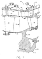
- Fig. 1 is a partial vertical cross section of a gas turbine engine having a blisk of the present invention;
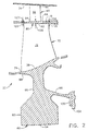
- Fig. 2 is a cross section of the blisk;
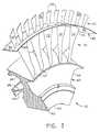
- Fig. 3 is an aft facing perspective of a sector of a blisk of the present invention;
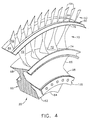
- Fig. 4 is a forward facing perspective of the sector of the blisk; and
- Fig. 5 is a schematic of an inner airfoil profile and an outer airfoil profile of the blisk.
- Corresponding reference characters indicate corresponding parts throughout the several views of the drawings.
- Referring now to the drawings and in particular to Fig. 1, a variable cycle gas turbine engine (partially shown) is designated in its entirety by the
reference number 10. Theengine 10 has a stator (generally designated by 12) and a high pressure or core rotor (generally designated by 14) rotatably mounted on the stator. Thecore rotor 14 includes an integrally bladed disk or "blisk", generally designated by 20, which is the subject of the present invention. - The
stator 12 includes a frame, generally designated by 30, upstream from theblisk 20. Theframe 30 includes an outer duct, generally designated by 32, defining anouter flowpath passageway 34 and an inner duct, generally designated by 36, defining aninner flowpath passageway 38. A plurality of circumferentially spaced outer variable pitch stator vanes 40 and a plurality of circumferentially spaced inner variablepitch stator vanes 42 are pivotally mounted in theouter flowpath passageway 34 and theinner flowpath passageway 38, respectively, for directing flow upstream from theblisk 20. A plurality of circumferentially spaced outerstationary stator vanes 44 is mounted downstream from the blisk for directing flow through theouter passageway 34, and a plurality of circumferentially spaced inner variablepitch stator vanes 46 is pivotally mounted downstream from theblisk 20 for directing flow through theinner passageway 38. The amount of air passing through theouter passageway 34 can be adjusted to change the thrust and fuel consumption of theengine 10. As the features of thestator 12 are conventional, they will not be described in further detail. - As illustrated in Fig. 2, the
blisk 20 includes an annular disk, generally designated by 60, having ahub 62 surrounding acentral opening 64, aweb 66 extending generally radially outward from the hub and arim 68 surrounding the web. An inner row of blades, generally designated by 70, including a plurality of circumferentially spacedairfoils 72, is integrally formed with thedisk 60 as part of therim 68. Each of theairfoils 72 of the inner row ofblades 70 extends generally radially outward from aroot 74 positioned adjacent therim 68 of thedisk 60 to atip 76 opposite the root. Theblisk 20 also includes an annular splitter, generally designated by 80, integrally formed with the inner row ofblades 70 and surrounding thetips 76 of theairfoils 72. Thesplitter 80 has aninner surface 82 facing inward toward thetips 76 of theairfoils 72 of the inner row ofblades 70 and anouter surface 84 opposite the inner surface. An outer row ofblades 90 including a plurality of circumferentially spacedairfoils 92 is integrally formed with thesplitter 80. Each of theairfoils 92 of the outer row ofblades 90 extends generally radially outward from aroot 94 positioned adjacent theouter surface 84 of thesplitter 80 to atip 96 opposite the root. Theblisk 20 also includes anarm 98 which extends rearward to aflange 100 configured for connecting the blisk to ashaft 102 which extends axially through theengine 10 to the high pressure turbine (not shown). - As shown in Figs. 3 and 4, there are
more airfoils 92 in the outer row ofblades 90 than there areairfoils 72 in the inner row ofblades 70. In one embodiment, there are twice asmany airfoils 92 in the outer row ofblades 90 as there are in the inner row ofblades 70. In the illustrated embodiment, half of theairfoils 92 in the outer row ofblades 90 are positioned directly radially outboard from theairfoils 72 in the inner row ofblades 70, and the other half of the airfoils in the outer row of blades are positioned halfway between the first half of the airfoils. As will be appreciated by those skilled in the art, this configuration minimizes stress in thesplitter 80 and maximizes fatigue life. - As illustrated in Fig. 5, each
airfoil 92 in the outer row ofblades 90 has amidspan chord length 110 less than about 75 percent of amidspan chord length 112 of theairfoils 72 in the inner row ofblades 70. In one embodiment, themidspan chord length 110 of theouter airfoils 92 is less than about 60 percent of themidspan chord length 112 of theinner airfoils 72. In one embodiment, themidspan chord length 110 of theouter airfoils 92 is about 54 percent of themidspan chord length 112 of theinner airfoils 72. As will be appreciated by those skilled in the art, the stresses in theinner airfoils 72 are reduced by reducing thechord length 110 of theouter airfoils 92. The fatigue life of the airfoils is improved by decreasing their peak stresses. In addition, increasing the number of outer airfoils provides increased tip airfoil solidity which may provide increased performance relative to a blisk having an equal number of inner and outer airfoils. - As illustrated in Fig. 2, the
splitter 80 has athickness 120 at a leadingedge 122, athickness 124 at atrailing edge 126 and athickness 128 halfway between the leading and trailing edges. To further reduce loading on the inner row ofblades 70, thethicknesses trailing edges thickness 128 of thesplitter 80 immediately inboard from the outer row ofblades 90. As will be appreciated by those skilled in the art, thethickness 128 of thesplitter 80 inboard from theblades 90 can be optimized to obtain a desired fatigue life. - Although the
blisk 20 may be made using other methods without departing from the scope of the present invention, in one embodiment the blisk is formed from a single piece of material (e.g., by milling on a numerically controlled machine) so that the inner and outer airfoils, the splitter and a disk are integral. Further, theblisk 20 may be made of any conventional material used to manufacture gas turbine engine rotor components (e.g., a titanium or nickel base alloy) without departing from the scope of the present invention. - Although the
blisk 20 described above is used in a compressor section of the engine as a core driven fan stage, those skilled in the art will appreciate that the present invention may also be applied to other portions of agas turbine engine 10 such as in the fan section or the turbine section. - When introducing elements of the present invention or the preferred embodiment(s) thereof, the articles "a", "an", "the" and "said" are intended to mean that there are one or more of the elements. The terms "comprising", "including" and "having" are intended to be inclusive and mean that there may be additional elements other than the listed elements.
Claims (8)
- A blisk (20) for use in a turbine engine (10) comprising:an annular disk (60) having a hub (62) surrounding a central opening (64), a web (66) extending generally radially outward from the hub (62) and a rim (68) surrounding the web (66);an inner row of blades (70) including a plurality of circumferentially spaced airfoils (72) integrally formed with the disk (60), each of said airfoils (72) of said inner row of blades (70) extending generally radially outward from a root (74) positioned adjacent the rim (68) of the disk (60) to a tip (76) opposite the root (74);an annular splitter (80) integrally formed with the inner row of blades (70) and surrounding the tips (76) of said plurality of airfoils (72) thereof, said splitter (80) having an inner surface (82) facing the tips (76) of the plurality of airfoils (72) of the inner row of blades (70) and an outer surface (84) opposite said inner surface (82); andan outer row of blades (90) including a plurality of circumferentially spaced airfoils (92) integrally formed with the splitter (80), each of said airfoils (92) of said outer row of blades (90) extending generally radially outward from a root (94) positioned adjacent the outer surface (84) of the splitter (80) to a tip (96) opposite the root (94), characterised in that there are more airfoils in said outer row of blades (90) than in said inner row of blades (70), and each airfoil (92) in said outer row of blades (90) has a midspan chord length (110) less than about 75 percent of a midspan chord length (112) of the airfoils (72) in said inner row of blades (70).
- A blisk (20) as set forth in claim 1 wherein there are twice as many airfoils in said outer row of blades (90) as in said inner row of blades (70).
- A blisk (20) as set forth in claim 2 wherein each of one half of the airfoils (92) in said outer row of blades (90) is positioned directly radially outboard from one of the airfoils (72) in said inner row of blades (70).
- A blisk (20) as set forth in claim 1 wherein the midspan chord length (110) of each airfoil (92) in said outer row of blades (90) is less than about 60 percent of the midspan chord length (112) of the airfoils (72) in said inner row of blades (70).
- A blisk (20) as set forth in claim 4 wherein the midspan chord length (110) of each airfoil (92) in said outer row of blades (90) is about 54 percent of the midspan chord length (112) of the airfoils (72) in said inner row of blades (70).
- A blisk (20) as set forth in claim 1 wherein the splitter (80) has a thickness (120) at a leading edge (122), a thickness (124) at a trailing edge (126) and a thickness (128) halfway between the leading and trailing edges (122, 126), and wherein the thickness (128) halfway between the leading and trailing edges is greater than the thicknesses (120, 124) at the leading and trailing edges (122, 126).
- A blisk (20) as set forth in claim 1 wherein said inner and outer rows of blades (70, 90) are configured for use as a core driven fan stage.
- A blisk (20) as set forth in claim 1 in combination with the turbine engine (10).
Applications Claiming Priority (2)
| Application Number | Priority Date | Filing Date | Title |
|---|---|---|---|
| US09/702,394 US6454535B1 (en) | 2000-10-31 | 2000-10-31 | Blisk |
| US702394 | 2000-10-31 |
Publications (3)
| Publication Number | Publication Date |
|---|---|
| EP1201878A2 EP1201878A2 (en) | 2002-05-02 |
| EP1201878A3 EP1201878A3 (en) | 2003-06-18 |
| EP1201878B1 true EP1201878B1 (en) | 2006-06-21 |
Family
ID=24821046
Family Applications (1)
| Application Number | Title | Priority Date | Filing Date |
|---|---|---|---|
| EP01307084A Expired - Lifetime EP1201878B1 (en) | 2000-10-31 | 2001-08-20 | Bladed rotor |
Country Status (7)
| Country | Link |
|---|---|
| US (1) | US6454535B1 (en) |
| EP (1) | EP1201878B1 (en) |
| JP (1) | JP5138138B2 (en) |
| BR (1) | BR0104895A (en) |
| CA (1) | CA2355428C (en) |
| DE (1) | DE60120875T2 (en) |
| ES (1) | ES2265397T3 (en) |
Families Citing this family (68)
| Publication number | Priority date | Publication date | Assignee | Title |
|---|---|---|---|---|
| US7399159B2 (en) * | 2003-06-25 | 2008-07-15 | Florida Turbine Technologies, Inc | Detachable leading edge for airfoils |
| US8641367B2 (en) | 2004-12-01 | 2014-02-04 | United Technologies Corporation | Plurality of individually controlled inlet guide vanes in a turbofan engine and corresponding controlling method |
| US8365511B2 (en) | 2004-12-01 | 2013-02-05 | United Technologies Corporation | Tip turbine engine integral case, vane, mount and mixer |
| US7845157B2 (en) | 2004-12-01 | 2010-12-07 | United Technologies Corporation | Axial compressor for tip turbine engine |
| US8061968B2 (en) | 2004-12-01 | 2011-11-22 | United Technologies Corporation | Counter-rotating compressor case and assembly method for tip turbine engine |
| WO2006059973A1 (en) * | 2004-12-01 | 2006-06-08 | United Technologies Corporation | Tip turbine engine with a heat exchanger |
| EP1828573B1 (en) | 2004-12-01 | 2010-06-16 | United Technologies Corporation | Hydraulic seal for a gearbox of a tip turbine engine |
| US8087885B2 (en) * | 2004-12-01 | 2012-01-03 | United Technologies Corporation | Stacked annular components for turbine engines |
| WO2006060004A1 (en) | 2004-12-01 | 2006-06-08 | United Technologies Corporation | Combustor for turbine engine |
| EP1825116A2 (en) * | 2004-12-01 | 2007-08-29 | United Technologies Corporation | Ejector cooling of outer case for tip turbine engine |
| US8757959B2 (en) | 2004-12-01 | 2014-06-24 | United Technologies Corporation | Tip turbine engine comprising a nonrotable compartment |
| EP1825113B1 (en) | 2004-12-01 | 2012-10-24 | United Technologies Corporation | Counter-rotating gearbox for tip turbine engine |
| EP1834067B1 (en) | 2004-12-01 | 2008-11-26 | United Technologies Corporation | Fan blade assembly for a tip turbine engine and method of assembly |
| US20090148273A1 (en) * | 2004-12-01 | 2009-06-11 | Suciu Gabriel L | Compressor inlet guide vane for tip turbine engine and corresponding control method |
| EP1831530B1 (en) | 2004-12-01 | 2009-02-25 | United Technologies Corporation | Compressor variable stage remote actuation for turbine engine |
| WO2006110123A2 (en) * | 2004-12-01 | 2006-10-19 | United Technologies Corporation | Vectoring transition duct for turbine engine |
| US8083030B2 (en) | 2004-12-01 | 2011-12-27 | United Technologies Corporation | Gearbox lubrication supply system for a tip engine |
| WO2006059974A1 (en) | 2004-12-01 | 2006-06-08 | United Technologies Corporation | Close coupled gearbox assembly for a tip turbine engine |
| DE602004016065D1 (en) | 2004-12-01 | 2008-10-02 | United Technologies Corp | VARIABLE BULB INLET BUCKET ASSEMBLY, TURBINE ENGINE WITH SUCH AN ARRANGEMENT AND CORRESPONDING STEERING PROCEDURE |
| US7882695B2 (en) | 2004-12-01 | 2011-02-08 | United Technologies Corporation | Turbine blow down starter for turbine engine |
| WO2006059970A2 (en) | 2004-12-01 | 2006-06-08 | United Technologies Corporation | Turbine engine with differential gear driven fan and compressor |
| US8104257B2 (en) * | 2004-12-01 | 2012-01-31 | United Technologies Corporation | Tip turbine engine with multiple fan and turbine stages |
| WO2006059986A1 (en) | 2004-12-01 | 2006-06-08 | United Technologies Corporation | Tip turbine engine and operating method with reverse core airflow |
| WO2006060003A2 (en) | 2004-12-01 | 2006-06-08 | United Technologies Corporation | Fan blade with integral diffuser section and tip turbine blade section for a tip turbine engine |
| DE602004028297D1 (en) * | 2004-12-01 | 2010-09-02 | United Technologies Corp | COMPREHENSIVE COMBUSTION CHAMBER FOR TOP TURBINE ENGINE |
| WO2006059989A1 (en) | 2004-12-01 | 2006-06-08 | United Technologies Corporation | Tip turbine engine support structure |
| WO2006059971A2 (en) | 2004-12-01 | 2006-06-08 | United Technologies Corporation | Tip turbine engine integral fan, combustor, and turbine case |
| DE602004032186D1 (en) | 2004-12-01 | 2011-05-19 | United Technologies Corp | Turbine blade group of a fan rotor and method for assembling such a group |
| US7883314B2 (en) | 2004-12-01 | 2011-02-08 | United Technologies Corporation | Seal assembly for a fan-turbine rotor of a tip turbine engine |
| DE602004019709D1 (en) * | 2004-12-01 | 2009-04-09 | United Technologies Corp | TIP TURBINE ENGINE AND CORRESPONDING OPERATING PROCESS |
| EP1825177B1 (en) | 2004-12-01 | 2012-01-25 | United Technologies Corporation | Inflatable bleed valve for turbine engine and method of controlling bleed air |
| US7927075B2 (en) | 2004-12-01 | 2011-04-19 | United Technologies Corporation | Fan-turbine rotor assembly for a tip turbine engine |
| EP1828567B1 (en) * | 2004-12-01 | 2011-10-12 | United Technologies Corporation | Diffuser aspiration for a tip turbine engine |
| US9003759B2 (en) | 2004-12-01 | 2015-04-14 | United Technologies Corporation | Particle separator for tip turbine engine |
| WO2006059996A1 (en) | 2004-12-01 | 2006-06-08 | United Technologies Corporation | Balanced turbine rotor fan blade for a tip turbine engine |
| WO2006060013A1 (en) | 2004-12-01 | 2006-06-08 | United Technologies Corporation | Seal assembly for a fan rotor of a tip turbine engine |
| WO2006059997A2 (en) | 2004-12-01 | 2006-06-08 | United Technologies Corporation | Annular turbine ring rotor |
| WO2006060014A1 (en) | 2004-12-01 | 2006-06-08 | United Technologies Corporation | Starter generator system for a tip turbine engine |
| EP1825112B1 (en) | 2004-12-01 | 2013-10-23 | United Technologies Corporation | Cantilevered tip turbine engine |
| WO2006060006A1 (en) | 2004-12-01 | 2006-06-08 | United Technologies Corporation | Tip turbine engine non-metallic tailcone |
| WO2006062497A1 (en) | 2004-12-04 | 2006-06-15 | United Technologies Corporation | Tip turbine engine mount |
| US7537430B2 (en) * | 2005-11-11 | 2009-05-26 | General Electric Company | Stacked reaction steam turbine rotor assembly |
| US7578655B1 (en) * | 2006-05-20 | 2009-08-25 | Florida Turbine Technologies, Inc. | Composite gas turbine fan blade |
| US7758303B1 (en) * | 2006-07-31 | 2010-07-20 | General Electric Company | FLADE fan with different inner and outer airfoil stagger angles at a shroud therebetween |
| US7736450B2 (en) * | 2006-09-29 | 2010-06-15 | General Electric Company | Varying fluence as a function of thickness during laser shock peening |
| US8192141B1 (en) * | 2007-04-05 | 2012-06-05 | The United States Of America As Represented By The Secretary Of The Air Force | Dual compression rotor |
| FR2914943B1 (en) * | 2007-04-13 | 2011-04-01 | Snecma | AUBE DE SOUFFLANTE |
| US8967945B2 (en) | 2007-05-22 | 2015-03-03 | United Technologies Corporation | Individual inlet guide vane control for tip turbine engine |
| CA2643587A1 (en) * | 2008-11-10 | 2010-05-10 | Organoworld Inc. | Turbine annular axial rotor |
| US8667774B2 (en) * | 2009-08-05 | 2014-03-11 | The Boeing Company | Coannular ducted fan |
| ITMI20120569A1 (en) * | 2012-04-06 | 2013-10-07 | Franco Tosi Meccanica S P A | ROTORIAL STAGE OF ASSORTED TURBINE WITH IMPROVED ROPE RATIO |
| US20140169972A1 (en) * | 2012-12-17 | 2014-06-19 | United Technologies Corporation | Fan with integral shroud |
| JP2016538449A (en) * | 2013-10-03 | 2016-12-08 | フランコ トシ メカニカ エス.ピー.エー. | Rotor stage of axial flow turbine with improved code / pitch ratio |
| WO2015057544A1 (en) * | 2013-10-16 | 2015-04-23 | United Technologies Corporation | Auxiliary power unit impeller blade |
| US10119403B2 (en) | 2014-02-13 | 2018-11-06 | United Technologies Corporation | Mistuned concentric airfoil assembly and method of mistuning same |
| EP3012411A1 (en) * | 2014-10-23 | 2016-04-27 | United Technologies Corporation | Integrally bladed rotor having axial arm and pocket |
| US20160208613A1 (en) * | 2015-01-15 | 2016-07-21 | United Technologies Corporation | Gas turbine engine integrally bladed rotor |
| US10563516B2 (en) * | 2016-07-06 | 2020-02-18 | General Electric Company | Turbine engine and method of assembling |
| US10415403B2 (en) * | 2017-01-13 | 2019-09-17 | Rolls-Royce North American Technologies Inc. | Cooled blisk for gas turbine engine |
| US10876407B2 (en) * | 2017-02-16 | 2020-12-29 | General Electric Company | Thermal structure for outer diameter mounted turbine blades |
| GB2561837A (en) * | 2017-04-24 | 2018-10-31 | Hieta Tech Limited | Turbine rotor, turbine, apparatus and method |
| US10670037B2 (en) * | 2017-11-21 | 2020-06-02 | General Electric Company | Turbofan engine's fan blade and setting method thereof |
| US10619483B2 (en) * | 2017-11-21 | 2020-04-14 | United Technologies Corporation | Partially shrouded gas turbine engine fan |
| US11060406B2 (en) * | 2019-10-11 | 2021-07-13 | Pratt & Whitney Canada Corp. | Rotor for gas turbine engine |
| US11428160B2 (en) | 2020-12-31 | 2022-08-30 | General Electric Company | Gas turbine engine with interdigitated turbine and gear assembly |
| BE1030046B1 (en) * | 2021-12-17 | 2023-07-17 | Safran Aero Boosters | MOBILE IMPELLER WITH SEVERAL ROWS OF BLADE |
| CN114542510A (en) * | 2022-02-23 | 2022-05-27 | 中国航发沈阳发动机研究所 | Self-adaptive variable-cycle engine fan rotor structure |
| BE1030473B1 (en) * | 2022-04-21 | 2023-11-27 | Safran Aero Boosters | ROTOR WITH MULTIPLE ROWS OF BLADE |
Family Cites Families (17)
| Publication number | Priority date | Publication date | Assignee | Title |
|---|---|---|---|---|
| US1263473A (en) | 1917-09-25 | 1918-04-23 | Gen Electric | Elastic-fluid turbine. |
| US1544318A (en) | 1923-09-12 | 1925-06-30 | Westinghouse Electric & Mfg Co | Turbine-blade lashing |
| GB585331A (en) | 1941-04-15 | 1947-02-05 | Alan Arnold Griffith | Improvements in or relating to internal-combustion turbines |
| GB586552A (en) | 1941-11-01 | 1947-03-24 | Karl Baumann | Improvements in or relating to internal combustion turbine plant |
| GB609322A (en) * | 1945-11-07 | 1948-09-29 | Power Jets Res & Dev Ltd | Improvements relating to axial-flow compressors and like machines, and blading thereof |
| US2999631A (en) | 1958-09-05 | 1961-09-12 | Gen Electric | Dual airfoil |
| GB904621A (en) * | 1960-04-09 | 1962-08-29 | Daimler Benz Ag | Improvements relating to the rotors of flow machines |
| US3070284A (en) | 1960-10-07 | 1962-12-25 | Gen Electric | Turbo-fan rotor |
| FR2096708B1 (en) | 1970-06-22 | 1974-03-22 | Snecma | |
| FR2141435B1 (en) | 1971-06-02 | 1973-06-29 | Snecma | |
| US4068471A (en) | 1975-06-16 | 1978-01-17 | General Electric Company | Variable cycle engine with split fan section |
| SU612056A1 (en) | 1977-03-09 | 1978-06-25 | Предприятие П/Я А-3513 | Double-level working blade of turbine machine |
| CH660207A5 (en) | 1983-06-29 | 1987-03-31 | Bbc Brown Boveri & Cie | Device for the damping of blade vibrations in axial flow turbo engines |
| JPS6196103A (en) * | 1984-10-16 | 1986-05-14 | Mitsubishi Heavy Ind Ltd | Multi-layered bucket of rotary machine |
| US5562419A (en) | 1995-06-06 | 1996-10-08 | General Electric Company | Shrouded fan blisk |
| US5988980A (en) | 1997-09-08 | 1999-11-23 | General Electric Company | Blade assembly with splitter shroud |
| US6250883B1 (en) * | 1999-04-13 | 2001-06-26 | Alliedsignal Inc. | Integral ceramic blisk assembly |
-
2000
- 2000-10-31 US US09/702,394 patent/US6454535B1/en not_active Expired - Lifetime
-
2001
- 2001-08-16 CA CA002355428A patent/CA2355428C/en not_active Expired - Fee Related
- 2001-08-20 DE DE60120875T patent/DE60120875T2/en not_active Expired - Lifetime
- 2001-08-20 EP EP01307084A patent/EP1201878B1/en not_active Expired - Lifetime
- 2001-08-20 ES ES01307084T patent/ES2265397T3/en not_active Expired - Lifetime
- 2001-08-30 JP JP2001260799A patent/JP5138138B2/en not_active Expired - Fee Related
- 2001-10-31 BR BR0104895-3A patent/BR0104895A/en not_active IP Right Cessation
Also Published As
| Publication number | Publication date |
|---|---|
| EP1201878A2 (en) | 2002-05-02 |
| BR0104895A (en) | 2002-07-30 |
| US6454535B1 (en) | 2002-09-24 |
| DE60120875T2 (en) | 2007-01-18 |
| JP5138138B2 (en) | 2013-02-06 |
| CA2355428C (en) | 2007-05-08 |
| JP2002180996A (en) | 2002-06-26 |
| DE60120875D1 (en) | 2006-08-03 |
| ES2265397T3 (en) | 2007-02-16 |
| CA2355428A1 (en) | 2002-04-30 |
| EP1201878A3 (en) | 2003-06-18 |
Similar Documents
| Publication | Publication Date | Title |
|---|---|---|
| EP1201878B1 (en) | Bladed rotor | |
| US7186079B2 (en) | Turbine engine disk spacers | |
| EP2333241B1 (en) | Duct with elongated ridge for a gas turbine engine | |
| EP2186997B1 (en) | Turbine engine rotor hub | |
| US11209013B2 (en) | Gas turbine engine airfoil | |
| EP1712738B1 (en) | Low solidity turbofan | |
| US10570915B2 (en) | Gas turbine engine airfoil | |
| CA2313929C (en) | Reduced-stress compressor blisk flowpath | |
| US10344601B2 (en) | Contoured flowpath surface | |
| US7874794B2 (en) | Blade row for a rotary machine and method of fabricating same | |
| US20160053617A1 (en) | Rotors with modulus mistuned airfoils | |
| US20040241003A1 (en) | Turbine blade dimple | |
| EP1942252B1 (en) | Airfoil tip for a rotor assembly | |
| EP3163028A1 (en) | Compressor apparatus | |
| US20060280610A1 (en) | Turbine blade and method of fabricating same | |
| GB2382382A (en) | A fan having two rows of blades of differing diameters | |
| US20170167503A1 (en) | Gas turbine engine airfoil | |
| US10294805B2 (en) | Gas turbine engine integrally bladed rotor with asymmetrical trench fillets | |
| EP3485171A2 (en) | Axial flow compressor with splitter blades | |
| US10914315B2 (en) | Gas turbine engine airfoil | |
| US20220235792A1 (en) | Gas turbine engine airfoil | |
| US11041507B2 (en) | Gas turbine engine airfoil | |
| US20230243268A1 (en) | Airfoils for gas turbine engines | |
| US20210115803A1 (en) | Gas turbine engine airfoil | |
| EP3296508B1 (en) | Full-span forward swept airfoils for gas turbine engines |
Legal Events
| Date | Code | Title | Description |
|---|---|---|---|
| PUAI | Public reference made under article 153(3) epc to a published international application that has entered the european phase |
Free format text: ORIGINAL CODE: 0009012 |
|
| AK | Designated contracting states |
Kind code of ref document: A2 Designated state(s): AT BE CH CY DE DK ES FI FR GB GR IE IT LI LU MC NL PT SE TR |
|
| AX | Request for extension of the european patent |
Free format text: AL;LT;LV;MK;RO;SI |
|
| PUAL | Search report despatched |
Free format text: ORIGINAL CODE: 0009013 |
|
| AK | Designated contracting states |
Designated state(s): AT BE CH CY DE DK ES FI FR GB GR IE IT LI LU MC NL PT SE TR |
|
| AX | Request for extension of the european patent |
Extension state: AL LT LV MK RO SI |
|
| RIC1 | Information provided on ipc code assigned before grant |
Ipc: 7F 01D 5/14 A Ipc: 7F 01D 5/22 B Ipc: 7F 02C 3/06 B Ipc: 7F 01D 5/02 B |
|
| 17P | Request for examination filed |
Effective date: 20031218 |
|
| AKX | Designation fees paid |
Designated state(s): DE ES FR GB IT SE |
|
| 17Q | First examination report despatched |
Effective date: 20040517 |
|
| GRAP | Despatch of communication of intention to grant a patent |
Free format text: ORIGINAL CODE: EPIDOSNIGR1 |
|
| GRAS | Grant fee paid |
Free format text: ORIGINAL CODE: EPIDOSNIGR3 |
|
| GRAA | (expected) grant |
Free format text: ORIGINAL CODE: 0009210 |
|
| AK | Designated contracting states |
Kind code of ref document: B1 Designated state(s): DE ES FR GB IT SE |
|
| REG | Reference to a national code |
Ref country code: GB Ref legal event code: FG4D |
|
| REF | Corresponds to: |
Ref document number: 60120875 Country of ref document: DE Date of ref document: 20060803 Kind code of ref document: P |
|
| PGFP | Annual fee paid to national office [announced via postgrant information from national office to epo] |
Ref country code: ES Payment date: 20060828 Year of fee payment: 6 |
|
| REG | Reference to a national code |
Ref country code: SE Ref legal event code: TRGR |
|
| ET | Fr: translation filed | ||
| REG | Reference to a national code |
Ref country code: ES Ref legal event code: FG2A Ref document number: 2265397 Country of ref document: ES Kind code of ref document: T3 |
|
| PLBE | No opposition filed within time limit |
Free format text: ORIGINAL CODE: 0009261 |
|
| STAA | Information on the status of an ep patent application or granted ep patent |
Free format text: STATUS: NO OPPOSITION FILED WITHIN TIME LIMIT |
|
| 26N | No opposition filed |
Effective date: 20070322 |
|
| PGFP | Annual fee paid to national office [announced via postgrant information from national office to epo] |
Ref country code: SE Payment date: 20060829 Year of fee payment: 6 |
|
| EUG | Se: european patent has lapsed | ||
| PG25 | Lapsed in a contracting state [announced via postgrant information from national office to epo] |
Ref country code: SE Free format text: LAPSE BECAUSE OF NON-PAYMENT OF DUE FEES Effective date: 20070821 |
|
| REG | Reference to a national code |
Ref country code: ES Ref legal event code: FD2A Effective date: 20070821 |
|
| PG25 | Lapsed in a contracting state [announced via postgrant information from national office to epo] |
Ref country code: ES Free format text: LAPSE BECAUSE OF NON-PAYMENT OF DUE FEES Effective date: 20070821 |
|
| REG | Reference to a national code |
Ref country code: FR Ref legal event code: PLFP Year of fee payment: 16 |
|
| PGFP | Annual fee paid to national office [announced via postgrant information from national office to epo] |
Ref country code: GB Payment date: 20160830 Year of fee payment: 16 Ref country code: IT Payment date: 20160824 Year of fee payment: 16 Ref country code: DE Payment date: 20160826 Year of fee payment: 16 |
|
| PGFP | Annual fee paid to national office [announced via postgrant information from national office to epo] |
Ref country code: FR Payment date: 20160825 Year of fee payment: 16 |
|
| REG | Reference to a national code |
Ref country code: DE Ref legal event code: R119 Ref document number: 60120875 Country of ref document: DE |
|
| GBPC | Gb: european patent ceased through non-payment of renewal fee |
Effective date: 20170820 |
|
| REG | Reference to a national code |
Ref country code: FR Ref legal event code: ST Effective date: 20180430 |
|
| PG25 | Lapsed in a contracting state [announced via postgrant information from national office to epo] |
Ref country code: GB Free format text: LAPSE BECAUSE OF NON-PAYMENT OF DUE FEES Effective date: 20170820 Ref country code: DE Free format text: LAPSE BECAUSE OF NON-PAYMENT OF DUE FEES Effective date: 20180301 |
|
| PG25 | Lapsed in a contracting state [announced via postgrant information from national office to epo] |
Ref country code: IT Free format text: LAPSE BECAUSE OF NON-PAYMENT OF DUE FEES Effective date: 20170820 Ref country code: FR Free format text: LAPSE BECAUSE OF NON-PAYMENT OF DUE FEES Effective date: 20170831 |