EP1201181A1 - Method and perimeter for examining visual functions of a human eye - Google Patents
Method and perimeter for examining visual functions of a human eye Download PDFInfo
- Publication number
- EP1201181A1 EP1201181A1 EP00810984A EP00810984A EP1201181A1 EP 1201181 A1 EP1201181 A1 EP 1201181A1 EP 00810984 A EP00810984 A EP 00810984A EP 00810984 A EP00810984 A EP 00810984A EP 1201181 A1 EP1201181 A1 EP 1201181A1
- Authority
- EP
- European Patent Office
- Prior art keywords
- eye
- perimeter
- camera
- deviation
- fixation mark
- Prior art date
- Legal status (The legal status is an assumption and is not a legal conclusion. Google has not performed a legal analysis and makes no representation as to the accuracy of the status listed.)
- Withdrawn
Links
Images
Classifications
-
- A—HUMAN NECESSITIES
- A61—MEDICAL OR VETERINARY SCIENCE; HYGIENE
- A61B—DIAGNOSIS; SURGERY; IDENTIFICATION
- A61B3/00—Apparatus for testing the eyes; Instruments for examining the eyes
- A61B3/02—Subjective types, i.e. testing apparatus requiring the active assistance of the patient
- A61B3/024—Subjective types, i.e. testing apparatus requiring the active assistance of the patient for determining the visual field, e.g. perimeter types
Definitions
- the invention relates to a method for checking visual functions of a human eye using a perimeter attached to a specific observer position in the direction of an observation axis is oriented, associated with a light source Means for the staggered generation of stimuli on selectable Locations in the vicinity of one arranged on the observation axis Fixation mark, with a computer and with a camera Observation of the eye.
- a perimeter is known from the applicant's CH-A-677 599 in which the subject's eye position is measured using a Camera is captured. If the deviation from the the ideal viewing direction is determined, the examination process interrupted, the subject was made aware of the deviation and relocated. During such an investigation, several such Interruptions occur. Delayed by these interruptions the examination process significantly and the duration of the examination will be extended accordingly.
- the invention is based on the object of a method create in which the disadvantages mentioned are avoided and therefore the duration of the examination is not interrupted is extended.
- the object is achieved in the generic method in that that the eye position is recorded with the camera, that the deviation the eye position from the defined fixation mark is determined automatically and that based on the determined deviation an automatic correction is carried out.
- the coordinates of the test sites are moved corrected based on the determined deviations so that there is no need to reposition the subject. Before every performance A stimulus turns the viewing direction using the camera or the position of the pupil of the examined eye. If a discrepancy is found, the Stimulus the corresponding corrected test location is calculated. This makes the subject independent of the subject's line of sight Stimulus always presented in the same place relative to the visual field. As mentioned, there is no need to interrupt the Investigation of the repositioning of the subject. Is conceivable also an embodiment in which a correction is made only after the Performance of the stimuli is performed. In both cases the subject did not have one during the entire examination Interruption disturbed.
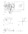
- Fig. 1 shows a perimeter 1 in which at a certain observer the eye 6 to be examined in an observation direction is fixed. The eye will be during an examination with suitable means, in timed staggering stimuli presented in the vicinity of an observer axis 9.
- the perimeter 1 is controlled by means of a computer 5. Becomes revelation here also referred to the applicant's CH-A-677 599 A5.
- Orientation around the observer eye 6 with reference to the observer axis 9 will facilitate the subject on this axis 9 a bright glowing mark (fixation mark) as a guide offered.
- This is done by an between an intermediate level 11 and partially transparent to the eyepiece 12, Deflecting mirror 28 directed towards the observer 10 Intersection between the deflecting mirror 28 and the observer axis 9 further intersects the optical axis 29 of two lenses 30, the axial with a light source 31 and an aperture 32nd is equipped.
- the aperture 32 determines the shape and size of the fixation mark.
- a further deflection mirror arranged in the optical axis 29 33 which is transparent for visible light and infrared Light reflecting is an IR sensitive CCD camera switched to the observer axis 9 with which the eye 6 can be viewed during an examination.
- the eye 6 with IR LEDs 38 becomes invisible to the test subject illuminated.
- the image captured by the camera 34 is in the Computer 5 evaluated.
- the position of the pupil 7 of the eye 6 determined and the deviations from the correct View direction and position are calculated. Such a possible Deviation in the viewing direction is shown schematically in Fig. 3.
- the pupil 7 of the eye 6 is located above the optical one Axis 9. Even if the eye 6 here shows the fixation mark 32 would be correctly fixed, for example a scotoma 3 according to FIG. 2 found in the wrong place, for example at 4.
- the position of the Stimulus test sites around the calculated values for example around corrected the value y according to FIG. 3.
- the correction will be made if necessary performed for each stimulus and in the x and y directions.
- the direction of view changes during an examination several times, the position of the person to be performed is correspondingly repeated several times Corrected stimulus.
- 4 schematically shows one such correction of a stimulus S.
- the fixation mark F is in the Zero point of the coordinate system.
- the eye 6 is correctly positioned and the line of sight is exactly on the optical axis 9, the camera 34 detects no deviation and accordingly a stimulus S presented. If the direction of view deviates, for example fix to point F 'according to Fig.
- this deviation captured by the camera 34 and in the computer 5 to a correction value converted. Because of this value it becomes a stimulus S 'presented at an appropriately corrected location.
- the stimulus S 'thus becomes relative despite the different viewing direction presented to the subject's field of vision at the correct location.
Landscapes
- Life Sciences & Earth Sciences (AREA)
- Health & Medical Sciences (AREA)
- Medical Informatics (AREA)
- Biophysics (AREA)
- Ophthalmology & Optometry (AREA)
- Engineering & Computer Science (AREA)
- Biomedical Technology (AREA)
- Heart & Thoracic Surgery (AREA)
- Physics & Mathematics (AREA)
- Molecular Biology (AREA)
- Surgery (AREA)
- Animal Behavior & Ethology (AREA)
- General Health & Medical Sciences (AREA)
- Public Health (AREA)
- Veterinary Medicine (AREA)
- Eye Examination Apparatus (AREA)
Abstract
Description
Die Erfindung betrifft ein Verfahren zum Prüfen visueller Funktionen eines menschlichen Auges mittels eines Perimeters, das an einer bestimmten Beobachterstelle in Richtung einer Beobachtungsachse orientiert ist, mit einer Lichtquelle zugeordneten Mitteln zur zeitlich gestaffelten Erzeugung von Stimuli an wählbaren Orten im Umfeld einer auf der Beobachtungsachse angeordneten Fixationsmarke, mit einem Rechner und mit einer Kamera zur Beobachtung des Auges.The invention relates to a method for checking visual functions of a human eye using a perimeter attached to a specific observer position in the direction of an observation axis is oriented, associated with a light source Means for the staggered generation of stimuli on selectable Locations in the vicinity of one arranged on the observation axis Fixation mark, with a computer and with a camera Observation of the eye.
Durch die CH-A-677 599 des Anmelders ist ein Perimeter bekannt geworden, bei dem die Augenposition des Probanden mittels einer Kamera erfasst wird. Wird eine zu grosse Abweichung von der idealen Blickrichtung festgestellt, wird der Untersuchungsablauf unterbrochen, der Proband auf die Abweichung aufmerksam gemacht und neu plaziert. Während einer Untersuchung können mehrere solche Unterbrechungen vorkommen. Durch diese Unterbrechungen verzögert sich der Untersuchungsablauf erheblich und die Untersuchungsdauer wird entsprechend verlängert.A perimeter is known from the applicant's CH-A-677 599 in which the subject's eye position is measured using a Camera is captured. If the deviation from the the ideal viewing direction is determined, the examination process interrupted, the subject was made aware of the deviation and relocated. During such an investigation, several such Interruptions occur. Delayed by these interruptions the examination process significantly and the duration of the examination will be extended accordingly.
Der Erfindung liegt die Aufgabe zugrunde, ein Verfahren zu schaffen, bei dem die genannten Nachteile vermieden sind und bei dem somit die Untersuchungsdauer nicht durch Unterbrechungen verlängert wird.The invention is based on the object of a method create in which the disadvantages mentioned are avoided and therefore the duration of the examination is not interrupted is extended.
Die Aufgabe ist beim gattungsgemässen Verfahren dadurch gelöst, dass mit der Kamera die Augenposition erfasst wird, dass die Abweichung der Augenposition von der definierten Fixationsmarke selbsttätig ermittelt wird und dass aufgrund der ermittelten Abweichung eine automatische Korrektur durchgeführt wird. Beim erfindungsgemässen Verfahren werden die Koordinaten der Testorte aufgrund der ermittelten Abweichungen korrigiert, so dass sich eine Neupositionierung des Probanden erübrigt. Vor jeder Darbietung eines Stimulus wird mittels der Kamera die Blickrichtung bzw. die Position der Pupille des untersuchten Auges ermittelt. Wird eine Abweichung festgestellt, so wird für den darzubietenden Stimulus der entsprechende korrigierte Testort berechnet. Damit wird unabhängig von der Blickrichtung des Probanden der Stimulus relativ zum Gesichtsfeld immer an derselben Stelle dargeboten. Wie erwähnt, erübrigt sich damit eine Unterbrechung der Untersuchung zur Neupositionierung des Probanden. Denkbar ist auch eine Ausführung, bei welcher eine Korrektur erst nach der Darbietung der Stimuli durchgeführt wird. In beiden Fällen wird der Proband währen der gesamten Untersuchung nicht durch eine Unterbrechung gestört.The object is achieved in the generic method in that that the eye position is recorded with the camera, that the deviation the eye position from the defined fixation mark is determined automatically and that based on the determined deviation an automatic correction is carried out. In the inventive The coordinates of the test sites are moved corrected based on the determined deviations so that there is no need to reposition the subject. Before every performance A stimulus turns the viewing direction using the camera or the position of the pupil of the examined eye. If a discrepancy is found, the Stimulus the corresponding corrected test location is calculated. This makes the subject independent of the subject's line of sight Stimulus always presented in the same place relative to the visual field. As mentioned, there is no need to interrupt the Investigation of the repositioning of the subject. Is conceivable also an embodiment in which a correction is made only after the Performance of the stimuli is performed. In both cases the subject did not have one during the entire examination Interruption disturbed.
Ein Ausführungsbeispiel der Erfindung wird nachfolgend anhand einer Zeichnung näher erläutert. Es zeigen:
- Fig. 1
- schematisch ein Perimeter zur Durchführung des Verfahrens,
- Fig. 2
- schematisch ein Gesichtsfeld mit der Darstellung eines Skotoms,
- Fig. 3
- schematisch eine von der idealen Position abweichende Augenposition und
- Fig. 4
- schematisch die Korrektur eines Stimulus-Testortes.
- Fig. 1
- schematically a perimeter for performing the method,
- Fig. 2
- schematically a visual field with the representation of a scotoma,
- Fig. 3
- schematically an eye position deviating from the ideal position and
- Fig. 4
- schematically the correction of a stimulus test site.
Die Fig. 1 zeigt ein Perimeter 1, in dem an einer bestimmten Beobachterstelle
das zu untersuchende Auge 6 in einer Beobachtungsrichtung
fixiert wird. Dem Auge werden während einer Untersuchung
mit geeigneten Mitteln in zeitlicher Staffelung Stimuli
im Umfeld einer Beobachterachse 9 präsentiert. Das Perimeter 1
wird mittels eines Rechners 5 gesteuert. Zur Offenbarung wird
hier auch auf die CH-A-677 599 A5 des Anmelders hingewiesen.Fig. 1 shows a
Um dem Beobachterauge 6 die Orientierung mit Bezug auf die Beobachterachse
9 zu erleichtern, wird dem Probanden auf diese Achse
9 eine hell leuchtende Marke (Fixationsmarke) als Orientierungshilfe
angeboten. Dazu dient ein zwischen einer Zwischenebene 11
und dem Okular 12 angeordneter, teilweise lichtdurchlässiger,
gegen die Beobachterstelle 10 gerichteter Umlenkspiegel 28. Den
Schnittpunkt zwischen dem Umlenkspiegel 28 und der Beobachterachse
9 schneidet weiter die optische Achse 29 von zwei Linsen
30, die achsial mit einer Lichtquelle 31 und einer Blende 32
ausgerüstet ist. Die Blende 32 bestimmt Form und Grösse der Fixationsmarke.Orientation around the observer eye 6 with reference to the
Über einen weiteren in der optischen Achse 29 angeordneten Umlenkspiegel
33, der für sichtbares Licht durchlässig und für infrarotes
Licht reflektierend ist, ist eine IR-empfindliche CCD-Kamera
auf die Beobachterachse 9 geschaltet, mit der das Auge 6
während einer Untersuchung betrachtet werden kann. Zu diesem
Zweck wird das Auge 6 mit IR-LEDs 38 für den Probanden unsichtbar
beleuchtet. Das von der Kamera 34 erfasste Bild wird im
Rechner 5 ausgewertet. Hierbei wird die Position der Pupille 7
des Auges 6 ermittelt und die Abweichungen von der korrekten
Blickrichtung bzw. Position werden berechnet. Eine solche mögliche
Abweichung in der Blickrichtung zeigt schematisch die Fig.
3. Die Pupille 7 des Auges 6 befindet sich hier oberhalb der optischen
Achse 9. Auch wenn das Auge 6 hier die Fixationsmarke 32
korrekt fixiert, würde beispielsweise ein Skotom 3 gemäss Fig. 2
an einer falschen Stelle, beispielsweise bei 4 gefunden.Via a further deflection mirror arranged in the
Zur Korrektur der genannten Abweichung wird nun die Position der
Stimulus-Testorte um die berechneten Werte, beispielsweise um
den Wert y gemäss Fig. 3, korrigiert. Die Korrektur wird nötigenfalls
für jeden Stimulus und in x- und y-Richtung durchgeführt.
Ändert sich während einer Untersuchung die Blickrichtung
mehrmals, so wird entsprechend mehrmals die Position des darzubietenden
Stimulus korrigiert. Die Fig. 4 zeigt schematisch eine
solche Korrektur eines Stimulus S. Die Fixationsmarke F steht im
Nullpunkt des Koordinatensystems. Ist das Auge 6 korrekt positioniert
und ist die Blickrichtung genau auf der optischen Achse
9, stellt die Kamera 34 keine Abweichung fest und entsprechend
wird ein bezüglich seiner Position nicht korrigierter Stimulus S
dargeboten. Bei einer Abweichung der Blickrichtung, beispielsweise
fixieren auf den Punkt F' gemäss Fig. 4, wird diese Abweichung
von der Kamera 34 erfasst und im Rechner 5 zu einem Korrekturwert
umgerechnet. Aufgrund dieses Wertes wird ein Stimulus
S' an einem entsprechend korrigierten Ort dargeboten. Der Stimulus
S' wird somit trotz der abweichenden Blickrichtung relativ
zum Gesichtsfeld des Probanden an der korrekten Stelle dargeboten.To correct the deviation mentioned, the position of the
Stimulus test sites around the calculated values, for example around
corrected the value y according to FIG. 3. The correction will be made if necessary
performed for each stimulus and in the x and y directions.
The direction of view changes during an examination
several times, the position of the person to be performed is correspondingly repeated several times
Corrected stimulus. 4 schematically shows one
such correction of a stimulus S. The fixation mark F is in the
Zero point of the coordinate system. The eye 6 is correctly positioned
and the line of sight is exactly on the
Claims (4)
Priority Applications (3)
| Application Number | Priority Date | Filing Date | Title |
|---|---|---|---|
| EP00810984A EP1201181A1 (en) | 2000-10-25 | 2000-10-25 | Method and perimeter for examining visual functions of a human eye |
| JP2001287612A JP2002143091A (en) | 2000-10-25 | 2001-09-20 | Method for examining visual function capacity of human eye, and perimeter for carrying out the method |
| US10/000,974 US20020047991A1 (en) | 2000-10-25 | 2001-10-24 | Method for testing visual functions of a human eye and perimeter for carrying out the method |
Applications Claiming Priority (1)
| Application Number | Priority Date | Filing Date | Title |
|---|---|---|---|
| EP00810984A EP1201181A1 (en) | 2000-10-25 | 2000-10-25 | Method and perimeter for examining visual functions of a human eye |
Publications (1)
| Publication Number | Publication Date |
|---|---|
| EP1201181A1 true EP1201181A1 (en) | 2002-05-02 |
Family
ID=8174988
Family Applications (1)
| Application Number | Title | Priority Date | Filing Date |
|---|---|---|---|
| EP00810984A Withdrawn EP1201181A1 (en) | 2000-10-25 | 2000-10-25 | Method and perimeter for examining visual functions of a human eye |
Country Status (3)
| Country | Link |
|---|---|
| US (1) | US20020047991A1 (en) |
| EP (1) | EP1201181A1 (en) |
| JP (1) | JP2002143091A (en) |
Cited By (2)
| Publication number | Priority date | Publication date | Assignee | Title |
|---|---|---|---|---|
| DE102008053015B3 (en) * | 2008-10-21 | 2010-03-04 | Technische Universität Ilmenau | Color-channel-selective stimulation process for visual system involves targeted selected tapping stimulation with glance follow-up |
| DE102009010628A1 (en) * | 2009-02-20 | 2010-08-26 | Technische Universität Ilmenau | Patient's visual system i.e. eye, stimulation method, involves detecting, compensating and considering geometrical and spectral false stimulation, fundus information and motion artifacts using correction parameters in iterative process |
Families Citing this family (4)
| Publication number | Priority date | Publication date | Assignee | Title |
|---|---|---|---|---|
| DE102006011624A1 (en) * | 2006-03-10 | 2007-09-13 | Carl Zeiss Meditec Ag | Device and method for the defined alignment of an eye |
| JP6062225B2 (en) * | 2012-11-28 | 2017-01-18 | 株式会社クリュートメディカルシステムズ | Visual function measuring device |
| JP6124330B2 (en) * | 2012-12-28 | 2017-05-10 | スカラ株式会社 | Visual field measuring device |
| WO2021096361A1 (en) * | 2019-11-14 | 2021-05-20 | Rijksuniversiteit Groningen | Method, system and computer program product for mapping a visual field |
Citations (3)
| Publication number | Priority date | Publication date | Assignee | Title |
|---|---|---|---|---|
| US3883235A (en) * | 1971-09-17 | 1975-05-13 | John R Lynn | Automatic visual field examination including fixation monitoring compensation |
| CH677599A5 (en) | 1988-09-22 | 1991-06-14 | Interzeag Ag | |
| US5550602A (en) * | 1994-11-09 | 1996-08-27 | Johannes Braeuning | Apparatus and method for examining visual functions |
Family Cites Families (1)
| Publication number | Priority date | Publication date | Assignee | Title |
|---|---|---|---|---|
| US4836670A (en) * | 1987-08-19 | 1989-06-06 | Center For Innovative Technology | Eye movement detector |
-
2000
- 2000-10-25 EP EP00810984A patent/EP1201181A1/en not_active Withdrawn
-
2001
- 2001-09-20 JP JP2001287612A patent/JP2002143091A/en active Pending
- 2001-10-24 US US10/000,974 patent/US20020047991A1/en not_active Abandoned
Patent Citations (3)
| Publication number | Priority date | Publication date | Assignee | Title |
|---|---|---|---|---|
| US3883235A (en) * | 1971-09-17 | 1975-05-13 | John R Lynn | Automatic visual field examination including fixation monitoring compensation |
| CH677599A5 (en) | 1988-09-22 | 1991-06-14 | Interzeag Ag | |
| US5550602A (en) * | 1994-11-09 | 1996-08-27 | Johannes Braeuning | Apparatus and method for examining visual functions |
Non-Patent Citations (2)
| Title |
|---|
| BERTERA J H ET AL: "STABILIZED RETINAL MAPPING OF KNOWN RETINAL LOCI", PROCEEDINGS OF THE ANNUAL NORTHEAST BIOENGINEERING CONFERENCE,US,NEW YORK, IEEE, vol. CONF. 14, 10 March 1988 (1988-03-10), pages 136 - 137, XP000010509 * |
| SUASTE E ET AL: "PUPILLARY RESPONSE QUANTIFICATION WITH AN IMAGE-PROCESSING SYSTEM IN CLINICAL PERIMETRY", MIDWEST SYMPOSIUM ON CIRCUITS AND SYSTEMS: PROCEEDINGS,US,NEW YORK, IEEE, vol. SYMP. 38, 13 August 1995 (1995-08-13), pages 1381 - 1384, XP000825319, ISBN: 0-7803-2973-2 * |
Cited By (3)
| Publication number | Priority date | Publication date | Assignee | Title |
|---|---|---|---|---|
| DE102008053015B3 (en) * | 2008-10-21 | 2010-03-04 | Technische Universität Ilmenau | Color-channel-selective stimulation process for visual system involves targeted selected tapping stimulation with glance follow-up |
| DE102009010628A1 (en) * | 2009-02-20 | 2010-08-26 | Technische Universität Ilmenau | Patient's visual system i.e. eye, stimulation method, involves detecting, compensating and considering geometrical and spectral false stimulation, fundus information and motion artifacts using correction parameters in iterative process |
| DE102009010628B4 (en) * | 2009-02-20 | 2010-10-14 | Technische Universität Ilmenau | Method and device for color channel-selective, fundus-controlled stimulation of the visual system |
Also Published As
| Publication number | Publication date |
|---|---|
| US20020047991A1 (en) | 2002-04-25 |
| JP2002143091A (en) | 2002-05-21 |
Similar Documents
| Publication | Publication Date | Title |
|---|---|---|
| CH696457A5 (en) | Ophthalmologic examination apparatus. | |
| EP0363610B1 (en) | Device for examining the visual functions of a human eye | |
| WO2018083323A1 (en) | A method for self-examination of an eye and ophthalmological self-examination apparatus | |
| DE69936214T2 (en) | Surgical eye fixation device | |
| EP0825826A1 (en) | Process and device for the parallel capture of visual information | |
| EP0495247B1 (en) | Process for the perimetry of the visual field of the eye | |
| EP1225454A2 (en) | Method and device for fixing a position | |
| EP0815482B1 (en) | Microscope, in particular a stereomicroscope | |
| DE10302401A1 (en) | surgical microscope | |
| EP3192431A2 (en) | Vision testing system and method for testing eyes | |
| EP1201181A1 (en) | Method and perimeter for examining visual functions of a human eye | |
| DE19502337C2 (en) | Device and method for testing visual functions | |
| EP3873322B1 (en) | Location-based quantification of impairment due to halo and scattered light | |
| CH688304A5 (en) | Ophthalmologic Geraet. | |
| EP1891890A1 (en) | Optical device, use of a an optical device according to the present invention and method for blocking light reflexes in the observation optical path of an optical device | |
| DE2939940A1 (en) | METHOD AND DEVICE FOR PRESENTING TESTS AGAINST A PERSON IN DIFFERENT DISTANCES | |
| EP1993431B1 (en) | Devices and methods for defined orientation of an eye | |
| EP1840627A2 (en) | Method and device for determining the orientation of an eye | |
| EP0815789B1 (en) | Apparatus for testing the visual field of the human eye | |
| EP1903928B1 (en) | Method and device for testing scotopic vision | |
| DE3731415A1 (en) | FACE FIELD EXAMINATION METHOD | |
| DE102014014093B4 (en) | Eye surgery system and method for operating an eye surgery system | |
| DE3143882A1 (en) | Method for securing the fixation of ophthalmological examination devices | |
| DE4232280A1 (en) | Retina examination instrument with optical fibre illumination - has regulator on holder of ophthalmoscopic observation system for pressure on proximal light conductor end face on sclera | |
| EP1224498A2 (en) | Combination magnifying device, particularly a microscope comprising a measuring device |
Legal Events
| Date | Code | Title | Description |
|---|---|---|---|
| PUAI | Public reference made under article 153(3) epc to a published international application that has entered the european phase |
Free format text: ORIGINAL CODE: 0009012 |
|
| AK | Designated contracting states |
Kind code of ref document: A1 Designated state(s): AT BE CH CY DE DK ES FI FR GB GR IE IT LI LU MC NL PT SE Kind code of ref document: A1 Designated state(s): DE GB |
|
| AX | Request for extension of the european patent |
Free format text: AL;LT;LV;MK;RO;SI |
|
| 17P | Request for examination filed |
Effective date: 20020518 |
|
| AKX | Designation fees paid |
Free format text: DE GB |
|
| 17Q | First examination report despatched |
Effective date: 20031105 |
|
| STAA | Information on the status of an ep patent application or granted ep patent |
Free format text: STATUS: THE APPLICATION IS DEEMED TO BE WITHDRAWN |
|
| 18D | Application deemed to be withdrawn |
Effective date: 20040316 |