EP1201120B1 - Wheelbarrow for transporting and distributing - Google Patents
Wheelbarrow for transporting and distributing Download PDFInfo
- Publication number
- EP1201120B1 EP1201120B1 EP01402343A EP01402343A EP1201120B1 EP 1201120 B1 EP1201120 B1 EP 1201120B1 EP 01402343 A EP01402343 A EP 01402343A EP 01402343 A EP01402343 A EP 01402343A EP 1201120 B1 EP1201120 B1 EP 1201120B1
- Authority
- EP
- European Patent Office
- Prior art keywords
- wheelbarrow
- handle
- distribution
- trough
- hatch
- Prior art date
- Legal status (The legal status is an assumption and is not a legal conclusion. Google has not performed a legal analysis and makes no representation as to the accuracy of the status listed.)
- Expired - Lifetime
Links
Images


Classifications
-
- B—PERFORMING OPERATIONS; TRANSPORTING
- B62—LAND VEHICLES FOR TRAVELLING OTHERWISE THAN ON RAILS
- B62B—HAND-PROPELLED VEHICLES, e.g. HAND CARTS OR PERAMBULATORS; SLEDGES
- B62B1/00—Hand carts having only one axis carrying one or more transport wheels; Equipment therefor
- B62B1/18—Hand carts having only one axis carrying one or more transport wheels; Equipment therefor in which the load is disposed between the wheel axis and the handles, e.g. wheelbarrows
-
- A—HUMAN NECESSITIES
- A01—AGRICULTURE; FORESTRY; ANIMAL HUSBANDRY; HUNTING; TRAPPING; FISHING
- A01K—ANIMAL HUSBANDRY; CARE OF BIRDS, FISHES, INSECTS; FISHING; REARING OR BREEDING ANIMALS, NOT OTHERWISE PROVIDED FOR; NEW BREEDS OF ANIMALS
- A01K5/00—Feeding devices for stock or game ; Feeding wagons; Feeding stacks
- A01K5/02—Automatic devices
- A01K5/0266—Automatic devices with stable trolleys, e.g. suspended
-
- B—PERFORMING OPERATIONS; TRANSPORTING
- B62—LAND VEHICLES FOR TRAVELLING OTHERWISE THAN ON RAILS
- B62B—HAND-PROPELLED VEHICLES, e.g. HAND CARTS OR PERAMBULATORS; SLEDGES
- B62B2501/00—Manufacturing; Constructional features
- B62B2501/06—Materials used
- B62B2501/065—Plastics
Definitions
- the invention relates to a wheelbarrow which can be used in particular for transport solid food for the purpose of distributing said solid food to livestock. See, e.g., US-A-2330944.
- the farmer uses a means of transport such as a trolley or wheelbarrow, or even buckets and a means of manual distribution such than a shovel, a bailer or a bucket.
- a means of transport such as a trolley or wheelbarrow, or even buckets
- a means of manual distribution such than a shovel, a bailer or a bucket.
- the breeder can also lift the bag of livestock feed on his shoulder and spread it irregularly moving along the feed table.
- the invention aims to remedy the aforementioned drawbacks, by providing a new wheelbarrow allowing direct supply from the silo to the table supply, and also allowing direct distribution on the table feeding, avoiding further handling of food.
- Another object of the invention is to provide a means of loading, of transport and distribution providing good distribution accuracy when moving this means of transport.
- the invention relates to a wheelbarrow, usable in particular for transport solid food for the purpose of distributing said solid food to livestock, comprising a tank supported by a wheel and at least one handle, the tank comprising a dispensing orifice whose opening and closing are controllable by actuation of said handle.
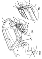
- Figure 1 schematically shows a perspective view of a wheelbarrow according to the invention.
- Figure 2 schematically shows a partial perspective view enlarged from detail II of figure 1.
- Figure 3 schematically shows a partial perspective view enlarged from detail III of figure 1.
- Figure 4 schematically shows a partial sectional view along the plane IV-IV of Figure 1 of a wheelbarrow according to the invention, in position with hatch completely opened.
- FIG. 5 schematically represents a partial sectional view similar to the Figure 4 of a wheelbarrow according to the invention, in the transport position.
- the wheelbarrow according to the invention designated as a whole by the reference 1 comprises a tank C, a wheel 2, a first handle 3 and a second handle 4.
- the tank C has a dispensing orifice 5 of which opening and closing can be controlled by actuating a handle, by example of the first handle 3.
- the tank C is preferably made of a synthetic material, for example in polyethylene.
- the tank C is produced by rotational molding, which has the advantage of constituting on the side of the handles 3 and 4 extensions 6 and 7 forming wheelbarrow support stand in rest position.
- Tank C presents advantageously a conformation adapted to support the rotation bearings of the wheel and pivot bearings of at least one handle 3 or 4.
- the tank C is extended at the front by a bearing support conformation of the wheel 2 and comprises a double wall intended to be drilled for fixing a pivot bearing of handle 3 or 4 by means of a through fixing screw V.
- handle 4 is not an operating handle, handle 4 is advantageously pivotally mounted like the actuating handle 3, so to follow the movement of the user's hands.
- Each metal handle 3 or 4 is thus constituted by a pivoting tube extending towards tank C with respect to which it pivots about an axis substantially horizontal, in both directions of pivoting.
- the distribution hatch 11 is preferably a mounted sliding hatch in a frame 12 fixed to the tank of the wheelbarrow by a screwing, riveting or any other way of joining.
- the frame 12 has a lower part ensuring a regular flow of the food passing through orifice 5: for this purpose, it is advantageous to extend or constitute the lower part of the frame 12 to form a distribution chute 13 having substantially the same slope as the flow slope of the orifice 5 of the tank C.
- the metal frame 12 has a guide surface 12a against which the hatch 11 is applied by two spring leaves 14 fixed by screwing to the tank C by through screws 15.
- Each leaf spring 14 has a conformation with two elastic wings 14a, 14b. The ends of the elastic wings 14a, 14b apply the hatch 11 against the frame guide surface 12a 12.
- This elasticity of the hatch 11, during its downward vertical movement, can be used to bypass obstacles (e.g. solid grains) preventing total closure of port 5 and this without mechanical risk (forcing).
- obstacles e.g. solid grains
- the wheelbarrow is advantageously provided with an indexing means indicating the position of the actuating handle 3.
- a plate 16 can be provided integral with the handle 3: this graduated plate 16 cooperates with an index 17 fixed on tank C or coming from material with tank C, to indicate a closed state or full opening or a state chosen from several intermediate opening states partial of the hatch 11 and the orifice 5 for the flow of solid materials.
- This relative indexing position between the graduation of the plate 16 and the arrow 17 corresponds to the chosen open position of the hatch 11 applied by the springs 14 against the frame 12.
- these adjustment notches 18 allow the ends of the elastic wings 14a, 14b to enter the hollows defined by these notches 18, so as to prevent any vertical sliding of the hatch 11 during the transport of the wheelbarrow, in particular in the event of strong vibrations of the tank from a movement on uneven ground.
- the wheelbarrow according to the invention can, in other alternative embodiments of the tank, be used for any other application requiring regular distribution of a material during the movement of the wheelbarrow: distribution of granules, gravel, or other materials of all kinds.
Abstract
Description
L'invention est relative à une brouette utilisable notamment pour le transport d'aliments solides en vue de distribuer lesdits aliments solides au bétail d'élevage. Voir p.e. le document US-A-2330944.The invention relates to a wheelbarrow which can be used in particular for transport solid food for the purpose of distributing said solid food to livestock. See, e.g., US-A-2330944.
Actuellement, la distribution des aliments solides ou des compléments d'aliments pour le bétail se fait mécaniquement ou manuellement.Currently, the distribution of solid foods or food supplements for cattle is done mechanically or manually.
Lorsque la distribution des aliments telle que granulés, farine, tourteaux, bouchons ou autres aliments solides se fait mécaniquement, on utilise une machine désileuse et mélangeuse, auto-motrice ou attelée à un tracteur. Cette distribution mécanique, coûteuse en raison du coût des matériels correspondants, est effectuée principalement dans des élevages de grande taille.When distributing food such as pellets, flour, oil cakes, plugs or other solid food is done mechanically, we use a machine silage unloader and mixer, self-propelled or coupled to a tractor. This distribution mechanical, expensive because of the cost of the corresponding materials, is carried out mainly in large farms.
Lorsque la distribution des aliments solides se fait manuellement, par exemple dans des élevages de petite taille, l'éleveur utilise un moyen de transport tel qu'un chariot ou une brouette, ou encore des seaux et un moyen de distribution manuelle telle qu'une pelle, une écope ou un godet. Alternativement, l'éleveur peut également soulever le sac d'aliments pour bétail sur son épaule et le répandre irrégulièrement en se déplaçant le long de la table d'alimentation.When the distribution of solid food is done manually, for example in small farms, the farmer uses a means of transport such as a trolley or wheelbarrow, or even buckets and a means of manual distribution such than a shovel, a bailer or a bucket. Alternatively, the breeder can also lift the bag of livestock feed on his shoulder and spread it irregularly moving along the feed table.
La distribution manuelle, plus économique que la distribution mécanique, ne donne cependant pas satisfaction : les opérations de distribution manuelle sont souvent longues et fastidieuses et la distribution est très approximative. En outre, les aliments doivent être manipulés deux fois dans le cas d'une brouette ou d'un chariot : une première fois pour charger le chariot ou la brouette, et une deuxième fois pour distribuer les aliments transportés par le chariot et la brouette.Manual distribution, more economical than mechanical distribution, does not however not satisfactory: manual distribution operations are often long and tedious and the distribution is very approximate. In addition, foods must be handled twice in the case of a wheelbarrow or a cart: a first time to load the cart or wheelbarrow, and a second time to distribute food transported by the cart and wheelbarrow.
L'invention a pour but de remédier aux inconvénients précités, en fournissant une nouvelle brouette permettant un approvisionnement direct du silo à la table d'alimentation, et permettant également une distribution directe sur la table d'alimentation, en évitant de nouvelles manipulations des aliments.The invention aims to remedy the aforementioned drawbacks, by providing a new wheelbarrow allowing direct supply from the silo to the table supply, and also allowing direct distribution on the table feeding, avoiding further handling of food.
Un autre but de l'invention est de fournir un moyen de chargement, de transport et de distribution fournissant une bonne précision de distribution lors du déplacement régulier de ce moyen de transport. Another object of the invention is to provide a means of loading, of transport and distribution providing good distribution accuracy when moving this means of transport.
L'invention a pour objet une brouette, utilisable notamment pour le transport d'aliments solides en vue de distribuer lesdits aliments solides au bétail d'élevage, comportant une cuve supportée par une roue et au moins une poignée, la cuve comportant un orifice de distribution dont l'ouverture et la fermeture sont commandables par actionnement de ladite poignée.The invention relates to a wheelbarrow, usable in particular for transport solid food for the purpose of distributing said solid food to livestock, comprising a tank supported by a wheel and at least one handle, the tank comprising a dispensing orifice whose opening and closing are controllable by actuation of said handle.
Selon d'autres caractéristiques de l'invention :
- ladite poignée d'actionnement est montée à pivotement par rapport à la cuve, de manière à ouvrir, puis à fermer l'orifice de distribution en tournant la poignée dans un premier sens de pivotement, puis dans le sens opposé audit premier sens.
- l'orifice de distribution est fermé par une trappe coulissante montée dans un cadre.
- la brouette comporte des crans de réglage de la trappe coulissante dans une position choisie.
- des moyens élastiques de maintien sont prévus pour maintenir la trappe coulissante dans une position choisie lors du déplacement de la brouette.
- la partie inférieure du cadre se raccorde à une conformation évasée formant goulotte de distribution.
- la cuve est conformée pour supporter des paliers de pivotement de ladite poignée d'actionnement et des paliers de rotation de la roue.
- la cuve est fabriquée en matière synthétique, par exemple en polyéthylène, de préférence par rotomoulage.
- la cuve comporte une double paroi et se prolonge du côté de la poignée par au moins une béquille de support.
- la brouette comporte un moyen d'indexation indiquant la position de ladite poignée d'actionnement correspondant à une position choisie d'ouverture de distribution.
- said actuating handle is pivotally mounted relative to the tank, so as to open and then close the dispensing orifice by turning the handle in a first pivoting direction, then in the direction opposite to said first direction.
- the dispensing orifice is closed by a sliding hatch mounted in a frame.
- the wheelbarrow has notches for adjusting the sliding hatch in a chosen position.
- elastic retaining means are provided to hold the sliding hatch in a position chosen when the wheelbarrow is moved.
- the lower part of the frame is connected to a flared conformation forming a distribution chute.
- the tank is shaped to support pivot bearings of said actuating handle and rotational bearings of the wheel.
- the tank is made of synthetic material, for example polyethylene, preferably by rotational molding.
- the tank has a double wall and is extended on the side of the handle by at least one support stand.
- the wheelbarrow comprises an indexing means indicating the position of said actuating handle corresponding to a chosen position of dispensing opening.
L'invention sera mieux comprise grâce à la description qui va suivre donnée à titre d'exemple non limitatif en référence aux dessins annexés dans lesquels :The invention will be better understood thanks to the description which will follow given to by way of nonlimiting example with reference to the appended drawings in which:
La figure 1 représente schématiquement une vue en perspective d'une brouette selon l'invention. Figure 1 schematically shows a perspective view of a wheelbarrow according to the invention.
La figure 2 représente schématiquement une vue en perspective partielle agrandie du détail II de la figure 1.Figure 2 schematically shows a partial perspective view enlarged from detail II of figure 1.
La figure 3 représente schématiquement une vue partielle en perspective agrandie du détail III de la figure 1.Figure 3 schematically shows a partial perspective view enlarged from detail III of figure 1.
La figure 4 représente schématiquement une vue partielle en coupe selon le plan IV-IV de la figure 1 d'une brouette selon l'invention, en position avec trappe totalement ouverte.Figure 4 schematically shows a partial sectional view along the plane IV-IV of Figure 1 of a wheelbarrow according to the invention, in position with hatch completely opened.
La figure 5 représente schématiquement une vue partielle en coupe analogue à la figure 4 d'une brouette selon l'invention, en position de transport.FIG. 5 schematically represents a partial sectional view similar to the Figure 4 of a wheelbarrow according to the invention, in the transport position.
En référence aux figures 1 à 5, les éléments identiques ou fonctionnellement équivalents sont repérés par des chiffres de référence identiques.With reference to FIGS. 1 to 5, the elements which are identical or functionally equivalents are identified by identical reference numbers.
La brouette selon l'invention désignée dans son ensemble par la référence 1
comporte une cuve C, une roue 2, une première poignée 3 et une deuxième poignée 4.The wheelbarrow according to the invention designated as a whole by the reference 1
comprises a tank C, a
Selon l'invention, la cuve C comporte un orifice 5 de distribution dont
l'ouverture et la fermeture sont commandables par actionnement d'une poignée, par
exemple de la première poignée 3.According to the invention, the tank C has a dispensing
La cuve C est de préférence réalisée en une matière synthétique, par exemple en
polyéthylène. Avantageusement, la cuve C est réalisée par rotomoulage, ce qui présente
l'avantage de constituer du côté des poignées 3 et 4 des prolongements 6 et 7 formant
béquille de support de la brouette en position de repos. La cuve C présente
avantageusement une conformation adaptée pour supporter les paliers de rotation de la
roue et les paliers de pivotement d'au moins une poignée 3 ou 4. A cet effet, la cuve C
se prolonge à l'avant par une conformation de support de palier de la roue 2 et comporte
une double paroi destinée à être percée pour la fixation d'un palier de pivotement de
poignée 3 ou 4 au moyen d'une vis V de fixation traversante.The tank C is preferably made of a synthetic material, for example in
polyethylene. Advantageously, the tank C is produced by rotational molding, which has
the advantage of constituting on the side of the
Bien que la poignée 4 ne soit pas une poignée d'actionnement, la poignée 4 est
avantageusement montée à pivotement comme la poignée 3 d'actionnement, de manière
à suivre le mouvement des mains de l'utilisateur.Although handle 4 is not an operating handle, handle 4 is
advantageously pivotally mounted like the
Chaque poignée métallique 3 ou 4 est ainsi constituée par un tube pivotant se
prolongeant vers la cuve C par rapport à laquelle elle pivote autour d'un axe
sensiblement horizontal, dans les deux sens de pivotement. Each
Sur la figure 4, le pivotement complet de la poignée 3 vers la gauche déplace un
levier 9 solidaire de la poignée 3, qui déplace à son tour une tringle 10 articulée à une
extrémité au levier 9 et à l'autre extrémité à une trappe 11 de fermeture de l'orifice 5. Le
pivotement de la poignée 3 assure ainsi le relèvement de la tringle 10 et l'ouverture de la
trappe 11 d'obturation de l'orifice 5.In FIG. 4, the complete pivoting of the
Sur la figure 5 le pivotement en sens opposé de la poignée 3 déplace le levier 9
vers le bas et provoque la descente de la tringle 10 et la fermeture de l'orifice 5 au
moyen de la trappe 11.In FIG. 5, the pivoting in the opposite direction of the
La trappe 11 de distribution est de préférence une trappe coulissante montée
dans un cadre 12 fixé à la cuve de la brouette par un vissage, rivetage ou tout autre
moyen de solidarisation.The
Le cadre 12 présente une partie inférieure assurant un écoulement régulier des
aliments passant par l'orifice 5 : à cet effet, il est avantageux de prolonger ou de
constituer la partie inférieure du cadre 12 pour former une goulotte 13 de distribution
présentant sensiblement la même pente que la pente d'écoulement de l'orifice 5 de la
cuve C.The
Le cadre métallique 12 présente une surface de guidage 12a contre laquelle la
trappe 11 est appliquée par deux lames de ressort 14 fixées par vissage à la cuve C par
des vis traversantes 15. Chaque lame de ressort 14 présente une conformation avec deux
ailes élastiques 14a, 14b. Les extrémités des ailes élastiques 14a, 14b appliquent la
trappe 11 contre la surface 12a de guidage du cadre 12.The
Cette disposition assure que la trappe 11 dans sa position fermée (figure 5) est
appliquée contre la surface 12a en quatre points correspondant aux extrémités des ailes
élastiques 14a, 14b.This arrangement ensures that the
Cette élasticité de la trappe 11, durant son mouvement vertical descendant, lui
permet éventuellement de contourner des obstacles (grains solides par ex.) empêchant la
fermeture totale de l'orifice 5 et ceci sans risque mécanique (forçage).This elasticity of the
Pour accroítre la précision de distribution, on peut prévoir plusieurs positions d'ouverture parmi lesquelles l'éleveur pourra choisir celle qui lui convient en fonction de la nature des aliments à distribuer et de sa vitesse de déplacement le long de la table d'alimentation. To increase the distribution accuracy, several positions can be provided among which the breeder can choose the one that suits him according to the nature of the food to be distributed and its speed of movement along the table Power.
Ces différentes positions d'ouverture peuvent s'obtenir par un pivotement plus ou
moins important de la poignée 3. Pour reproduire toujours la même position d'ouverture,
on prévoit avantageusement que la brouette comporte un moyen d'indexation indiquant
la position de la poignée d'actionnement 3. A cet effet, on peut prévoir une plaquette 16
solidaire de la poignée 3 : cette plaquette graduée 16 coopère avec un index 17 fixé sur
la cuve C ou venant de matière avec la cuve C, pour indiquer un état de fermeture ou
d'ouverture complète ou un état choisi parmi plusieurs états intermédiaires d'ouverture
partielle de la trappe 11 et de l'orifice 5 d'écoulement de matériaux solides.These different opening positions can be obtained by more or less pivoting.
less important of
Cette position d'indexation relative entre la graduation de la plaquette 16 et la
flèche 17 correspond à la position d'ouverture choisie de la trappe 11 appliquée par les
ressorts 14 contre le cadre 12. Pour éviter toute modification d'ouverture lors du
déplacement de la brouette, on prévoit avantageusement des crans 18 de réglage sur la
trappe 11 : ces crans 18 de réglage permettent aux extrémités des ailes élastiques 14a,
14b de pénétrer dans les creux définis par ces crans 18, de manière à empêcher tout
glissement vertical de la trappe 11 lors du transport de la brouette, en particulier en cas
de fortes trépidations de la cuve provenant d'un déplacement sur un sol inégal.This relative indexing position between the graduation of the
Bien que particulièrement destinée à la distribution d'aliments solides, la brouette selon l'invention peut, dans d'autres variantes de réalisation de la cuve, être utilisée pour toute autre application nécessitant une distribution régulière d'un matériau au cours du déplacement de la brouette : distribution de granulés, de gravier, ou d'autres matériaux de toute nature.Although particularly intended for the distribution of solid food, the wheelbarrow according to the invention can, in other alternative embodiments of the tank, be used for any other application requiring regular distribution of a material during the movement of the wheelbarrow: distribution of granules, gravel, or other materials of all kinds.
Claims (11)
- A wheelbarrow (1), for use in particular for transporting solid feed with the intention of distributing the said solid feed to livestock being reared, having a trough (C) supported by a wheel (2) and at least one handle (3), the trough (C) having a distribution aperture (5), opening and closing of the said distribution aperture (5) being capable of control by actuating the said handle (3).
- A wheelbarrow according to Claim 1, characterised in that the said actuating handle (3) is mounted to pivot with respect to the trough (C) such that the distribution aperture (5) is opened and then closed by turning the handle in a first direction of pivoting and then in the opposite direction to the said first direction.
- A wheelbarrow according to Claim 1 or Claim 2, characterised in that the distribution aperture (5) is closed by a sliding hatch (11) mounted in a frame (12).
- A wheelbarrow according to Claim 3, characterised in that the wheelbarrow (1) has notches (18) for keeping the sliding hatch (11) in a selected position.
- A wheelbarrow according to Claim 3 or Claim 4, characterised in that resilient holding means (14) are provided in order to hold the sliding hatch (11) in a selected position when the wheelbarrow (1) is moved.
- A wheelbarrow according to Claims 3, 4 and 5, characterised in that the resilient holding means (14) allow complete closure whatever the grain size and texture of the feed distributed, without any mechanical risk.
- A wheelbarrow according to Claim 3, characterised in that the lower part of the frame (12) is connected to a portion in a widened shape (13) forming a distribution chute.
- A wheelbarrow (1) according to any one of the preceding claims, characterised in that the trough (C) is shaped to support bearings for pivoting of the said actuating handle (3) and bearings for rotation of the wheel.
- A wheelbarrow according to Claim 7, characterised in that the trough (C) is made from synthetic material, for example polyethylene, preferably by rotational moulding.
- A wheelbarrow according to Claim 8, characterised in that the trough (C) has a double wall and is prolonged on the handle side by at least one support leg (6, 7).
- A wheelbarrow (1) according to any one of the preceding claims, characterised in that the wheelbarrow (1) has an indexing means (16, 17) indicating that position of the said actuating handle (3) corresponding to a selected opening position for distribution.
Applications Claiming Priority (2)
| Application Number | Priority Date | Filing Date | Title |
|---|---|---|---|
| FR0013305A FR2815317B1 (en) | 2000-10-18 | 2000-10-18 | TRANSPORT AND DISTRIBUTION WHEELBARROW |
| FR0013305 | 2000-10-18 |
Publications (3)
| Publication Number | Publication Date |
|---|---|
| EP1201120A2 EP1201120A2 (en) | 2002-05-02 |
| EP1201120A3 EP1201120A3 (en) | 2003-01-02 |
| EP1201120B1 true EP1201120B1 (en) | 2003-11-05 |
Family
ID=8855452
Family Applications (1)
| Application Number | Title | Priority Date | Filing Date |
|---|---|---|---|
| EP01402343A Expired - Lifetime EP1201120B1 (en) | 2000-10-18 | 2001-09-12 | Wheelbarrow for transporting and distributing |
Country Status (4)
| Country | Link |
|---|---|
| EP (1) | EP1201120B1 (en) |
| AT (1) | ATE253481T1 (en) |
| DE (1) | DE60101132T2 (en) |
| FR (1) | FR2815317B1 (en) |
Families Citing this family (3)
| Publication number | Priority date | Publication date | Assignee | Title |
|---|---|---|---|---|
| CN106428130A (en) * | 2016-10-13 | 2017-02-22 | 天津恺丰义科技有限公司 | Planting soil transferring wheelbarrow device |
| FR3062362B1 (en) * | 2017-01-27 | 2019-07-26 | Bernard Vallez | BROOM FOR SPREADING MATERIAL |
| CN109625043A (en) * | 2018-12-03 | 2019-04-16 | 佛山科学技术学院 | A kind of feed feeding cart |
Family Cites Families (3)
| Publication number | Priority date | Publication date | Assignee | Title |
|---|---|---|---|---|
| US2330944A (en) * | 1943-03-17 | 1943-10-05 | Balls Edmond | Wheelbarrow |
| US2426081A (en) * | 1945-10-15 | 1947-08-19 | Millard F Cheek | Wheelbarrow |
| GB1558667A (en) * | 1976-11-26 | 1980-01-09 | Gunn A B | Feed distributor |
-
2000
- 2000-10-18 FR FR0013305A patent/FR2815317B1/en not_active Expired - Fee Related
-
2001
- 2001-09-12 EP EP01402343A patent/EP1201120B1/en not_active Expired - Lifetime
- 2001-09-12 DE DE60101132T patent/DE60101132T2/en not_active Expired - Lifetime
- 2001-09-12 AT AT01402343T patent/ATE253481T1/en not_active IP Right Cessation
Also Published As
| Publication number | Publication date |
|---|---|
| DE60101132T2 (en) | 2004-08-26 |
| DE60101132D1 (en) | 2003-12-11 |
| EP1201120A3 (en) | 2003-01-02 |
| ATE253481T1 (en) | 2003-11-15 |
| FR2815317B1 (en) | 2003-01-24 |
| EP1201120A2 (en) | 2002-05-02 |
| FR2815317A1 (en) | 2002-04-19 |
Similar Documents
| Publication | Publication Date | Title |
|---|---|---|
| EP1177742B1 (en) | Cosmetic case with invisible pivoting means | |
| FR2522922A1 (en) | DEVICE FOR SPREADING GRANULAR AND / OR PULVERULENT MATERIAL | |
| EP1201120B1 (en) | Wheelbarrow for transporting and distributing | |
| EP2014147B1 (en) | Distribution device with an improved storage tank | |
| FR2888717A1 (en) | Shelter device for e.g. lamb, has cage with door that includes leaves that are mounted on both sides of opening, and enclosure extending on each side of opening in opened position and formed such that it extends before opening | |
| FR2474632A1 (en) | CONTROLLABLE FLOW THROUGH | |
| EP0261008B1 (en) | Removable hinge, especially for a fishermen's seat box | |
| FR2810965A1 (en) | AGGREGATE DISPENSER | |
| EP3345475B1 (en) | Mixing wagon with lateral unloading device | |
| FR3026275A1 (en) | ENHANCER WITH ENHANCED REGULATION OF THE FOOD DISTRIBUTION | |
| FR2693627A1 (en) | Apparatus for the storage and distribution of grain food, in particular dog food. | |
| EP0951825B1 (en) | Poultry feeder, particularly for use in a poultry feeding installation | |
| FR3034619A1 (en) | FOOD DISTRIBUTION TRAILER FOR ANIMAL BREEDING ANIMALS | |
| FR2785767A1 (en) | Agricultural device, for mixing and distributing feed products for animals, has hopper fitted with internal longitudinal rotating mixer and tilting device to pivot hopper around axis on end of hopper with opening | |
| FR2897346A1 (en) | BULK PRODUCT DELIVERY BUCKET | |
| EP0791289B1 (en) | Apparatus for dispensing large bales | |
| FR2900791A1 (en) | LOADING AND UNLOADING BUCKET | |
| FR2525856A1 (en) | MOWER | |
| WO2009087281A2 (en) | Device for supporting, positioning and guiding a tool | |
| EP4005374A1 (en) | Mixer with a two-part unloading device | |
| FR2937963A1 (en) | Load i.e. hay bale, gripping and handling device for use in front of loader of tractor, has rod provided with set of cams to unlock slide with respect to frame when feeler is subjected to thrust directed horizontally from front towards back | |
| FR2712266A1 (en) | Trash can with foot-operated opening. | |
| FR2757013A1 (en) | SEWER WITH A WIDE WORKING WIDTH | |
| BE1000394A7 (en) | Cat feeding dish - has extended base and spring-loaded bracket operating opening cover when cat steps on it | |
| FR2759999A1 (en) | Loading-unloading device for fork lift truck |
Legal Events
| Date | Code | Title | Description |
|---|---|---|---|
| PUAI | Public reference made under article 153(3) epc to a published international application that has entered the european phase |
Free format text: ORIGINAL CODE: 0009012 |
|
| AK | Designated contracting states |
Kind code of ref document: A2 Designated state(s): AT BE CH CY DE DK ES FI FR GB GR IE IT LI LU MC NL PT SE TR |
|
| AX | Request for extension of the european patent |
Free format text: AL;LT;LV;MK;RO;SI |
|
| PUAL | Search report despatched |
Free format text: ORIGINAL CODE: 0009013 |
|
| 17P | Request for examination filed |
Effective date: 20021029 |
|
| AK | Designated contracting states |
Kind code of ref document: A3 Designated state(s): AT BE CH CY DE DK ES FI FR GB GR IE IT LI LU MC NL PT SE TR |
|
| AX | Request for extension of the european patent |
Free format text: AL;LT;LV;MK;RO;SI |
|
| RIC1 | Information provided on ipc code assigned before grant |
Free format text: 7B 62B 1/22 A, 7A 01K 5/00 B, 7A 01K 5/02 B |
|
| GRAH | Despatch of communication of intention to grant a patent |
Free format text: ORIGINAL CODE: EPIDOS IGRA |
|
| GRAS | Grant fee paid |
Free format text: ORIGINAL CODE: EPIDOSNIGR3 |
|
| GRAA | (expected) grant |
Free format text: ORIGINAL CODE: 0009210 |
|
| AKX | Designation fees paid |
Designated state(s): AT BE CH CY DE DK ES FI FR GB GR IE IT LI LU MC NL PT SE TR |
|
| AK | Designated contracting states |
Kind code of ref document: B1 Designated state(s): AT BE CH CY DE DK ES FI FR GB GR IE IT LI LU MC NL PT SE TR |
|
| PG25 | Lapsed in a contracting state [announced via postgrant information from national office to epo] |
Ref country code: TR Free format text: LAPSE BECAUSE OF FAILURE TO SUBMIT A TRANSLATION OF THE DESCRIPTION OR TO PAY THE FEE WITHIN THE PRESCRIBED TIME-LIMIT Effective date: 20031105 Ref country code: NL Free format text: LAPSE BECAUSE OF FAILURE TO SUBMIT A TRANSLATION OF THE DESCRIPTION OR TO PAY THE FEE WITHIN THE PRESCRIBED TIME-LIMIT Effective date: 20031105 Ref country code: IT Free format text: LAPSE BECAUSE OF FAILURE TO SUBMIT A TRANSLATION OF THE DESCRIPTION OR TO PAY THE FEE WITHIN THE PRESCRIBED TIME-LIMIT;WARNING: LAPSES OF ITALIAN PATENTS WITH EFFECTIVE DATE BEFORE 2007 MAY HAVE OCCURRED AT ANY TIME BEFORE 2007. THE CORRECT EFFECTIVE DATE MAY BE DIFFERENT FROM THE ONE RECORDED. Effective date: 20031105 Ref country code: AT Free format text: LAPSE BECAUSE OF FAILURE TO SUBMIT A TRANSLATION OF THE DESCRIPTION OR TO PAY THE FEE WITHIN THE PRESCRIBED TIME-LIMIT Effective date: 20031105 Ref country code: FI Free format text: LAPSE BECAUSE OF FAILURE TO SUBMIT A TRANSLATION OF THE DESCRIPTION OR TO PAY THE FEE WITHIN THE PRESCRIBED TIME-LIMIT Effective date: 20031105 Ref country code: CY Free format text: LAPSE BECAUSE OF FAILURE TO SUBMIT A TRANSLATION OF THE DESCRIPTION OR TO PAY THE FEE WITHIN THE PRESCRIBED TIME-LIMIT Effective date: 20031105 Ref country code: IE Free format text: LAPSE BECAUSE OF FAILURE TO SUBMIT A TRANSLATION OF THE DESCRIPTION OR TO PAY THE FEE WITHIN THE PRESCRIBED TIME-LIMIT Effective date: 20031105 Ref country code: GB Free format text: LAPSE BECAUSE OF FAILURE TO SUBMIT A TRANSLATION OF THE DESCRIPTION OR TO PAY THE FEE WITHIN THE PRESCRIBED TIME-LIMIT Effective date: 20031105 |
|
| REG | Reference to a national code |
Ref country code: GB Ref legal event code: FG4D Free format text: NOT ENGLISH |
|
| REG | Reference to a national code |
Ref country code: CH Ref legal event code: EP |
|
| REF | Corresponds to: |
Ref document number: 60101132 Country of ref document: DE Date of ref document: 20031211 Kind code of ref document: P |
|
| REG | Reference to a national code |
Ref country code: IE Ref legal event code: FG4D Free format text: FRENCH |
|
| REG | Reference to a national code |
Ref country code: CH Ref legal event code: NV Representative=s name: R. A. EGLI & CO. PATENTANWAELTE |
|
| PG25 | Lapsed in a contracting state [announced via postgrant information from national office to epo] |
Ref country code: DK Free format text: LAPSE BECAUSE OF FAILURE TO SUBMIT A TRANSLATION OF THE DESCRIPTION OR TO PAY THE FEE WITHIN THE PRESCRIBED TIME-LIMIT Effective date: 20040205 Ref country code: SE Free format text: LAPSE BECAUSE OF FAILURE TO SUBMIT A TRANSLATION OF THE DESCRIPTION OR TO PAY THE FEE WITHIN THE PRESCRIBED TIME-LIMIT Effective date: 20040205 Ref country code: GR Free format text: LAPSE BECAUSE OF FAILURE TO SUBMIT A TRANSLATION OF THE DESCRIPTION OR TO PAY THE FEE WITHIN THE PRESCRIBED TIME-LIMIT Effective date: 20040205 |
|
| PG25 | Lapsed in a contracting state [announced via postgrant information from national office to epo] |
Ref country code: ES Free format text: LAPSE BECAUSE OF FAILURE TO SUBMIT A TRANSLATION OF THE DESCRIPTION OR TO PAY THE FEE WITHIN THE PRESCRIBED TIME-LIMIT Effective date: 20040216 |
|
| NLV1 | Nl: lapsed or annulled due to failure to fulfill the requirements of art. 29p and 29m of the patents act | ||
| GBV | Gb: ep patent (uk) treated as always having been void in accordance with gb section 77(7)/1977 [no translation filed] |
Effective date: 20031105 |
|
| REG | Reference to a national code |
Ref country code: IE Ref legal event code: FD4D |
|
| PLBE | No opposition filed within time limit |
Free format text: ORIGINAL CODE: 0009261 |
|
| STAA | Information on the status of an ep patent application or granted ep patent |
Free format text: STATUS: NO OPPOSITION FILED WITHIN TIME LIMIT |
|
| PG25 | Lapsed in a contracting state [announced via postgrant information from national office to epo] |
Ref country code: LU Free format text: LAPSE BECAUSE OF NON-PAYMENT OF DUE FEES Effective date: 20040912 |
|
| PG25 | Lapsed in a contracting state [announced via postgrant information from national office to epo] |
Ref country code: BE Free format text: LAPSE BECAUSE OF NON-PAYMENT OF DUE FEES Effective date: 20040930 Ref country code: MC Free format text: LAPSE BECAUSE OF NON-PAYMENT OF DUE FEES Effective date: 20040930 |
|
| 26N | No opposition filed |
Effective date: 20040806 |
|
| BERE | Be: lapsed |
Owner name: *LA BUVETTE Effective date: 20040930 |
|
| PG25 | Lapsed in a contracting state [announced via postgrant information from national office to epo] |
Ref country code: FR Free format text: LAPSE BECAUSE OF NON-PAYMENT OF DUE FEES Effective date: 20060531 |
|
| REG | Reference to a national code |
Ref country code: FR Ref legal event code: ST Effective date: 20060531 |
|
| REG | Reference to a national code |
Ref country code: FR Ref legal event code: RN |
|
| REG | Reference to a national code |
Ref country code: FR Ref legal event code: RN |
|
| REG | Reference to a national code |
Ref country code: FR Ref legal event code: FC |
|
| BERE | Be: lapsed |
Owner name: *LA BUVETTE Effective date: 20040930 |
|
| PG25 | Lapsed in a contracting state [announced via postgrant information from national office to epo] |
Ref country code: PT Free format text: LAPSE BECAUSE OF NON-PAYMENT OF DUE FEES Effective date: 20040405 |
|
| PGRI | Patent reinstated in contracting state [announced from national office to epo] |
Ref country code: FR Effective date: 20060817 |
|
| REG | Reference to a national code |
Ref country code: FR Ref legal event code: PLFP Year of fee payment: 16 |
|
| PGFP | Annual fee paid to national office [announced via postgrant information from national office to epo] |
Ref country code: DE Payment date: 20160921 Year of fee payment: 16 Ref country code: CH Payment date: 20160920 Year of fee payment: 16 |
|
| PGFP | Annual fee paid to national office [announced via postgrant information from national office to epo] |
Ref country code: FR Payment date: 20160927 Year of fee payment: 16 |
|
| REG | Reference to a national code |
Ref country code: DE Ref legal event code: R119 Ref document number: 60101132 Country of ref document: DE |
|
| REG | Reference to a national code |
Ref country code: CH Ref legal event code: PL |
|
| REG | Reference to a national code |
Ref country code: FR Ref legal event code: ST Effective date: 20180531 |
|
| PG25 | Lapsed in a contracting state [announced via postgrant information from national office to epo] |
Ref country code: DE Free format text: LAPSE BECAUSE OF NON-PAYMENT OF DUE FEES Effective date: 20180404 Ref country code: CH Free format text: LAPSE BECAUSE OF NON-PAYMENT OF DUE FEES Effective date: 20170930 Ref country code: LI Free format text: LAPSE BECAUSE OF NON-PAYMENT OF DUE FEES Effective date: 20170930 |
|
| PG25 | Lapsed in a contracting state [announced via postgrant information from national office to epo] |
Ref country code: FR Free format text: LAPSE BECAUSE OF NON-PAYMENT OF DUE FEES Effective date: 20171002 |