EP1200883B1 - Electrical appliances and system for performing at least an action related to a time mark - Google Patents
Electrical appliances and system for performing at least an action related to a time mark Download PDFInfo
- Publication number
- EP1200883B1 EP1200883B1 EP01936590A EP01936590A EP1200883B1 EP 1200883 B1 EP1200883 B1 EP 1200883B1 EP 01936590 A EP01936590 A EP 01936590A EP 01936590 A EP01936590 A EP 01936590A EP 1200883 B1 EP1200883 B1 EP 1200883B1
- Authority
- EP
- European Patent Office
- Prior art keywords
- data
- programming
- time
- temporal
- module
- Prior art date
- Legal status (The legal status is an assumption and is not a legal conclusion. Google has not performed a legal analysis and makes no representation as to the accuracy of the status listed.)
- Expired - Lifetime
Links
Images

Classifications
-
- G—PHYSICS
- G05—CONTROLLING; REGULATING
- G05B—CONTROL OR REGULATING SYSTEMS IN GENERAL; FUNCTIONAL ELEMENTS OF SUCH SYSTEMS; MONITORING OR TESTING ARRANGEMENTS FOR SUCH SYSTEMS OR ELEMENTS
- G05B19/00—Programme-control systems
- G05B19/02—Programme-control systems electric
- G05B19/04—Programme control other than numerical control, i.e. in sequence controllers or logic controllers
- G05B19/042—Programme control other than numerical control, i.e. in sequence controllers or logic controllers using digital processors
- G05B19/0421—Multiprocessor system
-
- G—PHYSICS
- G05—CONTROLLING; REGULATING
- G05B—CONTROL OR REGULATING SYSTEMS IN GENERAL; FUNCTIONAL ELEMENTS OF SUCH SYSTEMS; MONITORING OR TESTING ARRANGEMENTS FOR SUCH SYSTEMS OR ELEMENTS
- G05B2219/00—Program-control systems
- G05B2219/20—Pc systems
- G05B2219/25—Pc structure of the system
- G05B2219/25403—Compare real clock time with programmed time, if equal execute next command
-
- G—PHYSICS
- G05—CONTROLLING; REGULATING
- G05B—CONTROL OR REGULATING SYSTEMS IN GENERAL; FUNCTIONAL ELEMENTS OF SUCH SYSTEMS; MONITORING OR TESTING ARRANGEMENTS FOR SUCH SYSTEMS OR ELEMENTS
- G05B2219/00—Program-control systems
- G05B2219/20—Pc systems
- G05B2219/25—Pc structure of the system
- G05B2219/25483—Synchronize several controllers using messages over data bus
-
- G—PHYSICS
- G05—CONTROLLING; REGULATING
- G05B—CONTROL OR REGULATING SYSTEMS IN GENERAL; FUNCTIONAL ELEMENTS OF SUCH SYSTEMS; MONITORING OR TESTING ARRANGEMENTS FOR SUCH SYSTEMS OR ELEMENTS
- G05B2219/00—Program-control systems
- G05B2219/20—Pc systems
- G05B2219/26—Pc applications
- G05B2219/2642—Domotique, domestic, home control, automation, smart house
Definitions
- the present invention relates to electrical apparatus which carries out less an action related to a location in time.
- the action in question may be an event such as the activation of electrical contacts, the transmission of a signal, the recording of an event with tracking in the time, etc., as well as internal management of various bodies, for example for a temporal parameterization vis-à-vis an external reference.
- each device constitutes a switch - with single or multiple output (s) - programmed for activate the exit (s) at chosen times, for example to provide and interrupt a power supply to stations connected to the outputs (sockets current, alarms, security systems, etc.) according to the time of day.
- the devices are totally dependent on the position central to be able to perform an action with a location in time. It results in a lower reliability compared to the first case in that damage at the central station may prevent the operation of all devices that depend on it. Moreover, if there was a disturbance on the communication link between the central station and one or more of the apparatus, they could no longer perform their duties properly. However, Such disturbances are not uncommon, as they may be caused by spurious signals (causing a missed action, or caused by untimely) or communication breaks. These disturbances can be constant over a long period of time, or occasional and which is the case for example with certain parasitic noise on the link between the central station and the devices.
- WO 98 30941 A discloses a household appliance provided with a control system having a memory in a first zone of which are stored the data necessary to perform the functions of base and a second area in which data are stored and programs that allow this device to perform additional functions in function of data coming from an external device such as a microcomputer or a remote control.
- An additional function concerns the time setting the clock of the device after a power failure, which is done by entering a simple instruction on the microcomputer or pressing a button appropriate remote control.
- This unit can operate in standalone mode, with sound own program and its own means of executing actions and measuring of time, while allowing to synchronize by signals on a reference external temporal
- the invention aims to enable, when several such devices are dependent on a common source of programming, to put in receiving programming data only the chosen device.
- the apparatus according to the invention is characterized in that it further comprises means for setting programming mode, in which the means of reception and recording of temporal programming data are assets, and means of putting out of programming mode, in which the means for receiving and recording temporal data of programming are inactive, said means for setting programming mode and said means for deactivating programming mode comprising interface means with a user.
- the programming data can be transmitted to all the devices of the whole, that is to say, not selectively, without disturbing the state unselected devices. It is then possible to get rid of the need to specify a designated device at the data source programming (as one would do by means of an address specific to a apparatus).
- the apparatus may nevertheless, for reasons of convenience, understand ways of presenting an identity established during a phase programming.
- the apparatus comprises an oscillator serving both to source of timing signals for the means of execution and source of periodic signal for the time measuring means.
- It can then comprise means of counting cycles of the signal periodic method for calculating the evolution of time in predetermined units (eg hours and minutes) from synchronization data previously acquired.
- the means for measuring the time can be configured to synchronize with each reception of synchronization data.
- the execution means may comprise activation means and for deactivating electrical contacts, for example in the form of at least one switch for opening and closing electrical contacts.
- the apparatus is in the form of module provided for removable attachment in an envelope.
- the signal receiving element is sensitive to infrared radiation.
- the receiver element is turned to a wall of the envelope to receive reflected light energy by the latter.
- the means for entering data from time programming are configured to allow to introduce a succession of such data to the chain, all of them being intended for a specific slave module.
- Time programming data preferably includes at least one datum relating to an action start time and a datum relating to an end of action moment.
- time programming data and the data of synchronization are advantageously developed in the form of frames distributed in fields according to a common structure.
- the apparatus comprises means for storing a the identity of a slave module associated with a program assigned to that apparatus.
- the synchronization data correspond to units of instantaneous time (for example hour, minute, seconds).
- the time interval separating the transmissions consecutive synchronization data may be substantially equal to one not elementary in the resolution of the programming data.
- the apparatus may further comprise means for executing a action according to said timing data of programming.
- module provided for fixing removable in an envelope.
- the signal emitter element preferably emits radiation infrared.
- It can be turned to a wall of the envelope to transmit to the latter a light energy for reflection towards at least one module slave.
- the link is unidirectional only.
- At least one master module and at least least one slave module are housed in a common envelope.
- the link of the master module to the slave module can be realized by optical path, for example in the infrared spectrum, with reflection on at least one reflecting surface of the common envelope.
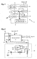
- FIG. 1 shows in the form of block diagram an electrical apparatus, said "slave module”, intended to establish or interrupt an electrical connection between two terminals 4, 6 at scheduled times of the day.
- a slave module 2 can be provided with a single pair of terminals 4, 6, as in the illustrated case, or several such pairs of terminals. In this In the latter case, different pairs of terminals can be programmed on periods independently of each other.
- the slave module 2 is managed by an associated processing logic 12 to a central memory 14.
- the latter has a fixed memory (ROM) containing data relating to the fixed aspects of the functioning of the device 2, for example the internal management codes of the various under control, and a random access memory (RAM) intended to receive inter alia programming data allowing the control of the block 8 free contact of potential based on data received from the outside, as will be described more far.
- ROM fixed memory
- RAM random access memory
- processing logic 12 and the central memory 14 operate in a known manner from binary signals clocked by means of a local oscillator.
- the programming data are downloaded by an infrared link by means of a receiving diode 16.
- This is a photodiode with integrated amplification with high immunity to light ambient, tuned to a frequency of the order of 950 nm and having a sensitivity of 0.2 to 0.4 milliwatt per square meter (mW / m 2 ).
- All of the aforementioned members 8-16 is powered by a unit of voltage output 18 connected externally to a low voltage network 20.
- the voltage output unit 18 may be constituted by a battery.
- the slave module 2 further comprises interface means with a user who, in the example, are constituted by a push-button switch 22 and, optionally, a display 24.
- FIG. 2 represents in simplified schematic form the part main processing logic 12, built around a microprocessor 12 'in accordance with a conventional architecture.
- the microprocessor 12 ' has a Din data entry which, in this case, is an input series type connected to the receiving diode 16, possibly via a circuit interface (not shown) for shaping the signals.
- the microprocessor 12 ' is furthermore connected to the bidirectional bus 10 in order to be able to exchange signals with the central memory 14 and with the block 8 free contact potential based on its internal management and data received from outside by means of the entrance Din.
- the microprocessor 12 ' is clocked by signals Sclk clock provided to a CLK input of the latter. These signals allow in particular to operate the internal logic of the microprocessor 12 ', which is synchronous type.
- Sclk clock signals are produced by an oscillator circuit specific 26 which can be either internal or external microprocessor 12 '.
- the oscillator is made from an ECL circuit (transmitter coupled logic) which includes an operational amplifier.
- the noninverting (positive) input 28a of the operational amplifier 28 is connected directly to the output 28b of the latter to form a positive loopback.
- the output 28b of the operational amplifier 28 is also looped back to the inverting (negative) input 28c of the latter through a resistor 30 of value R.
- the common node of the resistor 30 and the inverting input 28c is also connected to a frame of a capacitor 32 having a capacitance C.
- the other armature of capacitor 32 is connected to ground.
- the output 28b of the operational amplifier is biased to a negative voltage (for example - 5.2 volts) across a resistor 34 having a typical value of 3.9 kOhm.
- the frequency f of the oscillating signal Sclk, produced at the output 28b of the operational amplifier 28 is approximately 0.32 / RC.
- the values of R and C are chosen to give a frequency f of the order of 33 MHz.
- the microprocessor 12 ' is associated with a counting circuit 36 configured to form a time base from the Sclk signals of the oscillator 26.
- the counting circuit 36 has an input of counting Cin connected to the Sclk signal, and a Count output output that produces a pulse with a periodicity T for each number N of pulses of the Sclk signal totalized at the input Cin.
- T is equal to f / N.
- N is a value programmed according to the frequency f of the oscillator 26 of way that a pulse occurs regularly at the exit Cout at a predetermined time interval, for example once a minute or by fraction of a minute (for example every second).
- the microprocessor 12 receives the aforementioned pulses and exploits them to count the flow of time from a given reference. So, thanks to the pulses produced by the counting circuit 36, the microprocessor 12 'can fulfill a clock function recording the time, for example, time of day (hour, minutes, seconds, or time, minutes only).
- the microprocessor 12 comprises a reset output Raz, connected to a corresponding input of the counter 36, allowing the latter on the one hand to interrupt its count of N pulses in progress and on the other hand to simultaneously start counting N new pulses, and to continue to send a pulse after each count of N pulses.
- This reset function makes it possible in particular to resynchronize the counter 36, and hence the aforementioned clock, from a time signal outside received from the receive diode 16, as it will be detailed more far.
- the counter 36 is not necessarily a circuit physically separated from the microprocessor 12 '. It can indeed be integrated into microprocessor according to the availability of the internal functions of the latter. Of same, the clock function, ie the counting of time, can be performed outside the microprocessor 12 ', either by a specific circuit or by the counter 36.
- an important part of the base of time of the slave module 2 is constituted by the oscillator 26 which is intended for timing of the microprocessor 12 '. Thus, little - if not even - additional components are needed to implement this base of time.
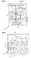
- FIG. 3 is a simplified block diagram of a device 40 for input and transmission of programming and synchronization data, suitable for cooperate with the slave module 2 of FIGS. 1 and 2.
- This apparatus 40 which will be hereinafter referred to as "master module” or "inter-hourly post", is intended to establish transmit to each slave module 2 on the one hand data from programming and secondly temporal data allowing a resynchronization of their internal clock constituted by the oscillator assembly 26, the counter 36 and the microprocessor 12 '.
- the master module 40 has a processing logic 42 designed to manage the internal functions of the latter as well as the transmission of programming and synchronization data.
- This logic of treatment 42 is carried out according to a conventional architecture based on a microprocessor or a microcontroller. It is connected to a central memory 44 via a bus bidirectionnel 46.
- the central memory 44 includes a frozen memory (ROM) containing a fixed program for performing pre-established tasks for logic 42 and a programmable random access memory (RAM) for others to store variable programming data.
- ROM frozen memory
- RAM programmable random access memory
- the master module 40 also includes a time base 43 of accuracy greater than the time base of the slave module 2.
- the time base of the master module is made from a high oscillator Frequency, driven by quartz. It can be possibly associated with circuits of stabilization against temperature differences.
- the processing logic 42 and the central memory 44 are moreover connected, by means of the bidirectional bus 46, to a display device 48, a user interface 50 and a block 52 "potential free contact".
- the latter is functionally identical to the block 8 "free contact of potential "of Figure 1, and will not be described again for the sake of brevity.
- this block 52 also includes two terminals 54 and 56 functionally equivalent to terminals 4 and 6 of block 8.
- the module master 40 can also perform the same functions as a module slave 2.
- Programming and control of block 52 free contact of potential are substantially identical to those of the slave module 2, except that in this case it is possible to manage the activation and deactivation times of the block 52 directly from the clock 43 by wiring.
- the processing logic 42 is also connected to an interface of transmission of data which, in the example, is in the form of a infrared emission diode 58.
- the emission characteristics of this diode 58 are adapted to the receiving characteristics of the diode 16 of each slave module 2 which depends on the master module.
- the diode 58 emits at a wavelength of 950 nanometers (nm), under a power of 40 milliwatts per steradian (mW / sr) and at an emission angle of between 90 ° and 150 °, for example 120 °, the emission being done in pulsed mode to maximize the reach with acceptable power.
- All of the aforementioned active members is supplied with voltage by a power supply 59 connected to a low voltage network.
- a power supply 59 connected to a low voltage network.
- the master module being intended to be joined with one or more apparatuses 16 in an envelope common, as will be explained later.
- FIG. 4 represents a part of a group of slave modules 2 depending on a master module 40.
- the slave modules 2 (two of which only are represented) and the master module 40 are mounted so removable on rails 60 attached to the structure of an envelope 62.
- the latter can be a cabinet, a housing, or any other enclosure capable of integrating modular electrical appliances.
- the optical path between the diode transmitter 58 of the master module 40 and the receiver diodes 16 of the modules slaves 2 for the communication of programming data and synchronization comprises at least one reflection of the optical energy by a part of the envelope 62, for example the rear face 62a or elements of side wall, upper or lower.
- the diodes 58 and 16 are placed facing a reflective portion of the envelope, here the rear wall 62a.
- the communication does not depend on a direct aim of the module master 40 to the different slave modules 2. This arrangement allows to establish a communication with a slave module 2 wherever that is last, either on the same rail 60 as the master module 40, or on another rail.
- the display 48 of the master module 40 represented in FIG. 4 is a screen on the one hand a digital display 48a for present the hours and minutes corresponding either at the present time or at a reference time, and secondly segments 48b arranged in a circle representing a 24-hour dial.
- the segments of the dial can be activated (for example by being darkened) to display at least one schedule.
- the screen 48 further comprises one or more displays alphanumeric 48c which make it possible to visualize, among other things, a number assigned to a block 8, 52 potential-free contact belonging either to the module master 40, either to a slave module 2. This number, the role of which is described more far, may be specific to either a slave module 2 or a block 8, 52 in the where the device manages several blocks independently of each other.
- the user interface 50 has a set of buttons 64 to program time slots and set the time of the module 40.
- the programmed time slots correspond to periods during which a block 8, 52 potential-free potential contact is active, this belonging either to the master module 40 or to a slave module 2 of the assembly.
- the button 22 is accessible for set the latter to receive programming data.
- a first press on the button 22 of a module Slave 2 selected activates the data reception mode, and a second pressing this button deactivates this mode.
- a display (not shown), for example in the form of a light-emitting diode flashing light, indicating that the device is in programming. This display may possibly indicate a number assigned to the device.
- the activation of the data reception mode is done by a button 22 'on the front side.
- the programming consists in establishing, from the master module 40, the minus a time slot during which the block 8 potential-free contact of a slave module 2 selected must be activated.
- programming allows to transfer hourly data individually to different devices depending on the master module, the latter being able to also be for example time stamps associated with an event.
- the programming phase is activated from a "normal" mode of operation, in which the master module 40 as well as the modules Slaves 2 are in the execution configuration of a program.
- the initial state is first in the mode normal (step E70).
- the processing logic 12 then remains ready to detect a first pressing the button 22 (step E72). As soon as we press on it, the apparatus enters the programming mode (step E74).
- step E76 At the level of the master module 40, we start with the opening of the menu programming (step E76). It then appears on the display screen 48 a choice of modes, including channel programming mode. We select this mode (step E78) by one of the buttons 64 of the user interface 50 ( Figure 4). This action puts the master module 40 in the mode of programming itself.
- the master module displays on the screen 48 a channel number, which can be either imposed in a sequence by the processing logic 42 is selected by the user (step E80): the optional character of this step is indicated by the dotted lines that delimit the corresponding box of the organization chart.
- Assigning a channel number allows to register within the master module a one-to-one relationship between following programming data and the slave module 2 selected for receive these data.
- the channel number can be incremented by one unit after each complete programming cycle of one slave module 2, so as to automatically assign a new number channel to the next slave module 2 to be programmed.
- this number can be selected by the user.
- the channel number thus recorded in the master module 40 can be also registered at the corresponding slave module 2, in order to allow the user to identify later which of the slave modules 2 which corresponds to the programming data associated with a given channel.
- the registration of the channel number at the level of the slave modules 2 can be carried out by various means. It can be performed for example by affixing a label with the channel number on a visible part of each slave module, or by writing the number directly on it. In variant, we can consider transmitting the information relating to the channel as well as determined to the slave module 2 being programmed so that it records it internally and can, if necessary, display it, for example on the display 24.
- this programming involves entering one or more activation time slots of the block 8 potential-free contact of the slave module 2 selected. To this end, you first enter the hour and minute of the beginning of the first range to be programmed (step E82).
- this data is displayed for control on the screen 48 (step E84).
- the screen 48 displays for control the range corresponding timetable, for example in the form of segments activated on the 48 hours 48b display (step E88).
- the master module 40 goes into a detection configuration of a possible new time slot to be programmed for the same slave module 2, which can handle several different time slots.
- the master module 40 is automatically repositioned on the step of entering a new start time (step E82) - corresponding in this case to a second time programming range - if it does not detect not an order to send the programmed data (loopback b1). In this way, he is possible to record in the master module 40 a succession of ranges schedules by subsequently defining a concatenation of hours and minutes of beginning and end.
- step E90 the user controls the transmission of the data thus programmed to the slave module 2 having been previously activated to acknowledge and register these data in the aforementioned step E72 (step E90).
- This command is performed by pressing one of the buttons 64 of the user interface 50.
- the processing logic 42 of the master 40 command module the transmission of the programmed data by means of the infrared diode 58 (step E92) and exit channel programming mode (step E94).
- Those data are structured according to specific frames, called configuration frames, which will be described later with reference to FIG.
- step E96 the slave module 2 is in a message waiting phase (step E96) which is successive to the change to programming mode.
- the slave module 2 On receipt of the programming data, the slave module 2 stores them in the central memory 14 (step E98) so as to be able to use them in normal mode to govern over time the functions of its block 8 potential free contact.
- the slave module 2 then remains in the programming mode, for wait for the arrival of any other data frame to be recorded, until the programming mode within the device is deactivated by a second press of the button 22 (step E100).
- the slave module When this button is pressed for the second time (the first one being the aforementioned step E72), the slave module returns to the normal mode (loopback b2) in which it executes the program thus loaded.
- FIG. 6 schematically represents a configuration frame 110 as transmitted by the master module 40 to download the data of programming to the slave module 2.
- each time slot programmed gives rise to a corresponding configuration frame. So, in the case of a programming of n time slots for a slave module 2, that is to say when n-1 loopbacks b1 (FIG. 5) are carried out, n frames of configuration 110 are transmitted during the step E92 IR message transmission.
- the configuration frames 110 are transmitted as signals binary digits according to a pre-established protocol. In the example, each frame occupies 12 bytes.
- the master module 40 When the master module 40 is in normal operating mode, it transmits at regular intervals, for example every minute, data daily schedules and schedules to each of the slave modules 2 which depends on it. These daily data are developed from the internal time base 43 at master module 40.
- each slave module 2 can be periodically reset on a more precise time base to avoid major drifts in time, and on the other hand stay synchronized with each other.
- the daily and hourly data are transmitted in the form of frames, called "current frames".
- FIG. 7 schematically represents a current frame 112 transmitted by the master module 40 in normal operating mode.
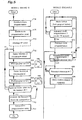
- step E120 We start with the setting of the slave module 2 in normal mode (step E120).
- the slave module 2 executes two routines in parallel: a first routine R1 for reading the current frames 112 in order to allow to resynchronize the internal clock and a second routine R2 of control of the 8 free potential contact block from the internal clock.
- These two routines R1 and R2 start from step 120 of setting in normal mode.
- Routine R1 begins with waiting for the next current frame 112 of the master module 40 (steps E122 and E124). As soon as a current frame 112 is received, this is transmitted from the receiving diode 16 to the processing logic 12 of each slave module 2. The data relating to the hour and the minutes - and possibly the data concerning the date - are read in the corresponding field (step E126) and used to resynchronize the internal clock (step E128). As explained above, this resynchronization is to reset the counter 36 (FIG. 2) and start again the measurement of the time by the internal clock of the module slave 2 from the new data provided by the current frame 112.
- the control routine R2 of the block 8 potential-free contact starts with setting the time according to the internal clock of the module slave (step E130).
- this step may include a calculation and / or conversion of a counting number of the counter 36 in hourly data in the same format as that used for recording of the programming data.
- the time established according to the internal clock is then compared with a start time of the time slot stored in the main memory 14 (step E132). If there is concordance, the block 8 potential-free contact is activated (step E134).
- step E136 the time established according to the internal clock is compared with a time of end of time slot stored in the central memory 14 (step E136). If there is a match, the 8 potential-free contact block is deactivated (step E138).
- the routine R2 then returns to the step E130 for setting the time according to the internal clock to repeat all of the steps E132 to E138.
- the internal time base of the slave module 2 essentially serves as a relay for temporal data from the master module 40.
- the control of the 8 free potential contact block is governed with high precision of the time base 43 of the master module 40, without it being necessary to physically achieve such a precise time base within of each slave module 2.
- the slave modules 2 can nevertheless perform their tasks programmed by referring to their internal timebase.
- the latter being used only as an auxiliary means, may be of design relatively simple and therefore less expensive than the module timebase master.
- the number of master and slave modules implemented in a installation is arbitrary. These modules can be grouped into one envelope, or distant from each other.
- programming frames and / or current frames can be carried out by any appropriate technical means: wired link, radio waves across the spectrum, or acoustic links.
- the action linked to a location in time can be other than activation and deactivation of contacts.
- This may include storage of time data, for example the time at which a event is detected within a slave module, which can be equipped one or more sensors of physical or electrical parameters: overvoltage detector (for example for a surge arrester function), smoke, burglary, temperature, lighting, anomaly on a system of data communication, etc.
Description
La présente invention concerne les appareils électriques qui réalisent au moins une action liée à un repérage dans le temps. L'action en question peut être une manifestation telle que l'activation de contacts électriques, la transmission d'un signal, l'enregistrement d'un événement avec repérage dans le temps de ce dernier, etc., ainsi qu'une gestion interne de divers organes, par exemple pour un paramétrage temporel vis-à-vis d'une référence externe.The present invention relates to electrical apparatus which carries out less an action related to a location in time. The action in question may be an event such as the activation of electrical contacts, the transmission of a signal, the recording of an event with tracking in the time, etc., as well as internal management of various bodies, for example for a temporal parameterization vis-à-vis an external reference.
Dans l'exemple non-limitatif de la présente description, l'action considérée se trouve être l'activation et la désactivation de contacts électriques en fonction de plages horaires programmées. Dans ce cas, chaque appareil constitue un commutateur - à simple ou multiples sortie(s) - programmé pour activer la ou les sortie(s) à des heures choisies, par exemple pour fournir et interrompre une alimentation vers des postes branchés sur les sorties (prises de courant, alarmes, systèmes de sécurité, etc.) selon les moments du jour.In the non-limiting example of the present description, the action considered happens to be the activation and deactivation of electrical contacts according to programmed time slots. In this case, each device constitutes a switch - with single or multiple output (s) - programmed for activate the exit (s) at chosen times, for example to provide and interrupt a power supply to stations connected to the outputs (sockets current, alarms, security systems, etc.) according to the time of day.
Lorsque l'on envisage de réaliser un ensemble comportant plusieurs appareils du type précité, deux conceptions principales peuvent être envisagées :
- soit chaque appareil est complètement autonome en ce qui concerne à la fois l'entrée, la gestion de données temporelles et la mesure du temps, afin de pouvoir fonctionner de manière totalement indépendante ; ceci est le cas notamment avec les commutateurs programmables du type électromécanique ou électronique qui intègrent une prise gigogne destinée à se brancher sur une prise de courant ;
- soit chaque appareil dépend d'un poste central pour recevoir des commandes de commutation, par exemple au moyen d'une liaison filaire, infrarouge ou radio, en fonction d'une programmation réalisée et gérée par le poste central ; l'appareil est dans ce cas simplement un organe télécommandé d'exécution de fonctions (par exemple de commutation), dépourvu de moyens internes de gestion et de mesure du temps.
- either each device is completely autonomous with regard to both the input, the temporal data management and the time measurement, in order to be able to operate completely independently; this is particularly the case with programmable switches of the electromechanical or electronic type which incorporate a socket for plugging into a socket;
- either each device depends on a central station to receive switching commands, for example by means of a wired connection, infrared or radio, according to a program performed and managed by the central station; the apparatus is in this case simply a remote control device for performing functions (for example switching), devoid of internal means of management and time measurement.
Dans le premier cas, on s'affranchit de moyens de communication de données temporelles nécessaires lorsque l'on met en oeuvre un système centralisé, mais moyennant les inconvénients suivants. D'une part, il est nécessaire de prévoir pour chaque appareil des moyens propres de mesure du temps qui, pour maintenir une précision adéquate sur des périodes raisonnables, doivent être précis. On prévoit à cette fin des bases de temps réalisées à partir d'oscillateurs spécifiques pilotés par quartz, associés à des moyens de programmation, de mise à l'heure et d'affichage. Or, dans un ensemble comportant un nombre relativement important d'appareils, la démultiplication de tels moyens grève sur le prix et augmente considérablement la complexité du système. Par ailleurs, la décentralisation de la base de temps et de la programmation rendent la gestion du système plus difficile. Il faut en effet prévoir une présence locale pour une programmation, et le maintien de la synchronisation des bases de temps individuelles requiert des remises à l'heure régulières au niveau de chaque appareil.In the first case, the means of communication of temporal data required when implementing a system centralized, but with the following disadvantages. On the one hand, it is necessary to provide for each device own means of measuring the time which, to maintain adequate accuracy over reasonable periods, must be precise. For this purpose, time bases based on specific oscillators controlled by quartz, combined with programming, time setting and display. Now, in a set with a relatively large number of devices, the multiplication of such means strike on the price and greatly increases the complexity of the system. In addition, the decentralization of the time base and the programming make system management more difficult. It is necessary to foresee a local presence for programming, and maintaining the synchronization of individual timebases requires time discounts regularly on each device.
Qui plus est, lorsque cette approche est mise en oeuvre dans un ensemble modulaire regroupé dans un espace limité, par exemple dans une enveloppe contenant divers modules, certains au moins des modules étant des appareils du type précité, la démultiplication des circuits de base de temps, d'affichage et d'interface d'entrée de programmation augmente sensiblement l'encombrement.Moreover, when this approach is implemented in a modular set grouped together in a limited space, for example in a envelope containing various modules, at least some of the modules being devices of the aforementioned type, the multiplication of the time base circuits, display and programming input interface significantly increases clutter.
Dans le second cas, les appareils sont totalement tributaires du poste central pour pouvoir effectuer une action avec un repérage dans le temps. Il en résulte une fiabilité inférieure par rapport au premier cas en ce sens qu'une avarie au niveau du poste central peut empêcher le fonctionnement de tous les appareils qui en dépendent. Par ailleurs, s'il se produisait une perturbation sur le lien de communication entre le poste central et l'un ou plusieurs des appareils, ces derniers ne pourraient plus assurer leurs fonctions correctement. Or, de telles perturbations ne sont pas rares, celles-ci pouvant être occasionnées par des signaux parasites (causant une action manquée, ou provoquée de manière intempestive) ou des ruptures de communication. Ces perturbations peuvent être présentes de manière constante sur une longue durée, ou occasionnelles et aléatoires, ce qui est le cas par exemple avec certains bruits parasites sur la liaison entre le poste central et les appareils. In the second case, the devices are totally dependent on the position central to be able to perform an action with a location in time. It results in a lower reliability compared to the first case in that damage at the central station may prevent the operation of all devices that depend on it. Moreover, if there was a disturbance on the communication link between the central station and one or more of the apparatus, they could no longer perform their duties properly. However, Such disturbances are not uncommon, as they may be caused by spurious signals (causing a missed action, or caused by untimely) or communication breaks. These disturbances can be constant over a long period of time, or occasional and which is the case for example with certain parasitic noise on the link between the central station and the devices.
On connaít par WO 98 30941 A un appareil électroménager muni d'un système de commande comportant une mémoire dans une première zone de laquelle sont stockées les données nécessaires pour effectuer les fonctions de base et une deuxième zone dans laquelle sont stockés des données et programmes permettant à cet appareil d'effectuer des fonctions additionnelles en fonction de données provenant d'un dispositif externe tel qu'un micro-ordinateur ou une télécommande. Une fonction additionnelle concerne la remise à l'heure de l'horloge de l'appareil après une coupure de courant, qui s'effectue en entrant une simple instruction sur le micro-ordinateur ou en pressant un bouton approprié de la télécommande.WO 98 30941 A discloses a household appliance provided with a control system having a memory in a first zone of which are stored the data necessary to perform the functions of base and a second area in which data are stored and programs that allow this device to perform additional functions in function of data coming from an external device such as a microcomputer or a remote control. An additional function concerns the time setting the clock of the device after a power failure, which is done by entering a simple instruction on the microcomputer or pressing a button appropriate remote control.
On connaít déjà par GB 2 060 953 A un interrupteur horaire qui comprend :
- des moyens de réception et d'enregistrement de données temporelles de programmation, émises sous forme de signaux ;
- des moyens d'exécution permettant la réalisation d'une action liée à un repérage dans le temps en fonction desdites données temporelles de programmation ;
- des moyens de réception de données de synchronisation, émises sous forme de signaux, permettant d'établir une synchronisation avec une référence temporelle externe ; et
- des moyens de mesure du temps, référencés à partir desdites données de synchronisation, permettant de fournir un repérage dans le temps auxdits moyens d'exécution ;
- means for receiving and recording temporal programming data, transmitted in the form of signals;
- execution means for performing an action related to a location in time according to said programming time data;
- means for receiving synchronization data, transmitted in the form of signals, making it possible to establish a synchronization with an external time reference; and
- time measuring means, referenced from said synchronization data, making it possible to provide a time tracking to said execution means;
Cet l'appareil peut fonctionner en mode autonome, disposant de son propre programme et de ses propres moyens d'exécution d'actions et de mesure du temps, tout en permettant de se synchroniser par signaux sur une référence temporelle externe.This unit can operate in standalone mode, with sound own program and its own means of executing actions and measuring of time, while allowing to synchronize by signals on a reference external temporal
L'invention vise à permettre, lorsque plusieurs tels appareils sont dépendants d'une source commune de programmation, de mettre en mode de réception de données de programmation seulement l'appareil choisi. The invention aims to enable, when several such devices are dependent on a common source of programming, to put in receiving programming data only the chosen device.
L'appareil selon l'invention se caractérise en ce qu'il comporte en outre des moyens de mise en mode de programmation, dans lequel les moyens de réception et d'enregistrement de données temporelles de programmation sont actifs, et des moyens de mise hors de mode de programmation, dans lequel les moyens de réception et d'enregistrement de données temporelles de programmation sont inactifs, lesdits moyens de mise en mode de programmation et lesdits moyens de mise hors de mode de programmation comportant des moyens d'interface avec un utilisateur.The apparatus according to the invention is characterized in that it further comprises means for setting programming mode, in which the means of reception and recording of temporal programming data are assets, and means of putting out of programming mode, in which the means for receiving and recording temporal data of programming are inactive, said means for setting programming mode and said means for deactivating programming mode comprising interface means with a user.
Ainsi, les données de programmation peuvent être transmises vers tous les appareils de l'ensemble, c'est-à-dire non sélectivement, sans perturber l'état des appareils non sélectionnés. Il est alors possible de s'affranchir de la nécessité de spécifier un appareil désigné au niveau de la source de données de programmation (comme on le ferait au moyen d'une adresse propre à un appareil).Thus, the programming data can be transmitted to all the devices of the whole, that is to say, not selectively, without disturbing the state unselected devices. It is then possible to get rid of the need to specify a designated device at the data source programming (as one would do by means of an address specific to a apparatus).
L'appareil peut néanmoins, pour des raisons de convenance, comprendre des moyens de présentation d'une identité établie lors d'une phase de programmation.The apparatus may nevertheless, for reasons of convenience, understand ways of presenting an identity established during a phase programming.
Avantageusement, l'appareil comprend un oscillateur servant à la fois de source de signaux de cadencement pour les moyens d'exécution et de source de signal périodique pour les moyens de mesure du temps.Advantageously, the apparatus comprises an oscillator serving both to source of timing signals for the means of execution and source of periodic signal for the time measuring means.
Il peut alors comprendre des moyens de comptage de cycles du signal périodique permettant le calcul de l'évolution du temps en unités prédéterminées (par exemple heures et minutes) à partir de données de synchronisation acquises antérieurement.It can then comprise means of counting cycles of the signal periodic method for calculating the evolution of time in predetermined units (eg hours and minutes) from synchronization data previously acquired.
Les moyens de mesure du temps peuvent être configurés pour se synchroniser à chaque réception de données de synchronisation.The means for measuring the time can be configured to synchronize with each reception of synchronization data.
Les moyens d'exécution peuvent comporter des moyens d'activation et de désactivation de contacts électriques, par exemple sous forme d'au moins un commutateur permettant l'ouverture et la fermeture de contacts électriques.The execution means may comprise activation means and for deactivating electrical contacts, for example in the form of at least one switch for opening and closing electrical contacts.
Dans le mode de réalisation décrit, l'appareil se présente sous forme de module prévu pour une fixation amovible dans une enveloppe.In the embodiment described, the apparatus is in the form of module provided for removable attachment in an envelope.
Egalement dans le mode de réalisation, l'élément récepteur de signaux est sensible à un rayonnement infrarouge. Also in the embodiment, the signal receiving element is sensitive to infrared radiation.
Dans ce cas, il est possible de prévoir que l'élément récepteur est tourné vers une paroi de l'enveloppe afin de recevoir une énergie lumineuse réfléchie par cette dernière.In this case, it is possible to predict that the receiver element is turned to a wall of the envelope to receive reflected light energy by the latter.
L'invention vise également un appareil (module maítre) destiné à transmettre des données temporelles de programmation et des données de synchronisation vers un appareil précité (module esclave), caractérisé en ce qu'il comprend :
- des moyens d'entrée de données de programmation temporelles ;
- des moyens d'élaboration et de transmission de signaux correspondant aux données temporelles de programmation ;
- des moyens formant horloge ; et
- des moyens d'élaboration et de transmission de signaux correspondant aux données de synchronisation à partir de données fournies par les moyens formant horloge, les données de synchronisation étant transmises à intervalles régulier ;
l'appareil étant configuré pour fonctionner selon un premier mode dans lequel il est actif pour permettre l'entrée de données de programmation temporelles et la transmission de signaux correspondant aux données de programmation, et selon un deuxième mode dans lequel il est actif pour permettre la transmission de signaux correspondant aux données de synchronisation, par sélection grâce à une interface utilisateur.The invention also relates to an apparatus (master module) for transmitting programming time data and synchronization data to an aforementioned apparatus (slave module), characterized in that it comprises:
- time programming data input means;
- means for generating and transmitting signals corresponding to the programming time data;
- clock means; and
- means for generating and transmitting signals corresponding to the synchronization data from data supplied by the clock means, the synchronization data being transmitted at regular intervals;
the apparatus being configured to operate in a first mode in which it is active to allow the input of time programming data and the transmission of signals corresponding to the programming data, and in a second mode in which it is active to enable the signal transmission corresponding to the synchronization data, by selection through a user interface.
De préférence, les moyens permettant l'entrée de données de programmation temporelles sont configurés pour permettre d'introduire une succession de telles données à la chaíne, l'ensemble de celles-ci étant destiné à un module esclave spécifique.Preferably, the means for entering data from time programming are configured to allow to introduce a succession of such data to the chain, all of them being intended for a specific slave module.
Les données de programmation temporelles comprennent de préférence au moins une donnée relative à un moment de début d'action et une donnée relative à un moment de fin d'action. Time programming data preferably includes at least one datum relating to an action start time and a datum relating to an end of action moment.
Les données de programmation temporelles et les données de synchronisation sont avantageusement élaborées sous forme de trames réparties en champs selon une structure commune.The time programming data and the data of synchronization are advantageously developed in the form of frames distributed in fields according to a common structure.
De préférence, l'appareil comprend des moyens de mémorisation d'une identité d'un module esclave associé à une programmation affectée à cet appareil.Preferably, the apparatus comprises means for storing a the identity of a slave module associated with a program assigned to that apparatus.
Dans le mode de réalisation envisagé, les données de synchronisation correspondent à des unités de temps instantané (par exemple heure, minutes, secondes).In the embodiment envisaged, the synchronization data correspond to units of instantaneous time (for example hour, minute, seconds).
Avantageusement, l'intervalle de temps séparant les transmissions consécutives des données de synchronisation peut être sensiblement égal à un pas élémentaire dans la résolution des données de programmation.Advantageously, the time interval separating the transmissions consecutive synchronization data may be substantially equal to one not elementary in the resolution of the programming data.
L'appareil peut comprendre en outre des moyens d'exécution d'une action en fonction desdites données temporelles de programmation. The apparatus may further comprise means for executing a action according to said timing data of programming.
Il peut se présenter sous forme de module prévu pour une fixation amovible dans une enveloppe.It can be in the form of module provided for fixing removable in an envelope.
L'élément émetteur de signaux émet de préférence par un rayonnement infrarouge.The signal emitter element preferably emits radiation infrared.
Il peut être tourné vers une paroi de l'enveloppe afin de transmettre vers cette dernière une énergie lumineuse pour réflexion vers au moins un module esclave.It can be turned to a wall of the envelope to transmit to the latter a light energy for reflection towards at least one module slave.
L'invention concerne également un ensemble de programmation et gestion d'actions liées à un repérage dans le temps, caractérisé en ce qu'il comprend :
- au moins un module esclave ;
- au moins un module maítre ; et
- des moyens de liaison permettant d'établir une liaison du premier appareil vers le deuxième appareil.
- at least one slave module;
- at least one master module; and
- connecting means for establishing a connection of the first device to the second device.
Avantageusement - notamment pour des raisons de simplicité de mise en oeuvre - la liaison est unidirectionnelle seulement.Advantageously - especially for the sake of simplicity of implementation implemented - the link is unidirectional only.
Dans le mode de réalisation envisagé, au moins un module maítre et au moins un module esclave sont logés dans une enveloppe commune.In the embodiment envisaged, at least one master module and at least least one slave module are housed in a common envelope.
La liaison du module maítre vers le module esclave peut être réalisée par chemin optique, par exemple dans le spectre infrarouge, avec réflexion sur au moins une surface réfléchissante de l'enveloppe commune.The link of the master module to the slave module can be realized by optical path, for example in the infrared spectrum, with reflection on at least one reflecting surface of the common envelope.
D'autres avantages et caractéristiques de l'invention apparaítront plus clairement à la lecture de la description qui suit d'un mode de réalisation préféré, donnée purement à titre d'exemple non limitatif, à l'aide des dessins annexés dans lesquels :
- la figure 1 est un schéma bloc simplifié d'un appareil électrique programmé, dit "module esclave", destiné à accomplir au moins une action liée à un repérage dans le temps, conforme à la présente invention ;
- la figure 2 est un schéma simplifié d'une partie de la logique de traitement incorporée dans le module esclave de la figure 1 et permettant la mesure du temps ;
- la figure 3 est un schéma bloc simplifié d'un appareil d'établissement et de transmission de données de programmation et de synchronisation pour le module esclave, dit "module maítre", conforme à la présente invention ;
- la figure 4 est une vue partielle et schématique d'un ensemble de modules esclaves et d'un module maítre au sein d'une enveloppe ;
- la figure 5 est un organigramme représentant les étapes principales de la programmation d'un module esclave à partir d'un module maítre ;
- la figure 6 est un schéma de principe représentant les différents champs constitutifs d'une trame dite "de configuration" émise par le module maítre vers un module esclave lors d'un mode de programmation ;
- la figure 7 est un schéma de principe d'une trame dite "courante" émise par le module maítre vers au moins un module esclave durant un mode de fonctionnement normal ; et
- la figure 8 est un organigramme représentant les étapes principales exécutées par un module esclave en mode de fonctionnement normal.
- FIG. 1 is a simplified block diagram of a programmed electrical device, called a "slave module", intended to perform at least one time-tracking action in accordance with the present invention;
- FIG. 2 is a simplified diagram of a part of the processing logic incorporated in the slave module of FIG. 1 and allowing the measurement of time;
- FIG. 3 is a simplified block diagram of an apparatus for establishing and transmitting programming and synchronization data for the slave module, referred to as the "master module", in accordance with the present invention;
- Figure 4 is a partial schematic view of a set of slave modules and a master module within an envelope;
- Figure 5 is a flowchart showing the main steps of programming a slave module from a master module;
- FIG. 6 is a block diagram representing the various constituent fields of a so-called "configuration" frame transmitted by the master module to a slave module during a programming mode;
- FIG. 7 is a block diagram of a so-called "current" frame sent by the master module to at least one slave module during a normal operating mode; and
- Fig. 8 is a flowchart showing the main steps performed by a slave module in normal operating mode.
La figure 1 montre sous forme de schéma bloc un appareil électrique, dit
"module esclave", destiné à établir ou à interrompre une liaison électrique entre
deux bornes 4, 6 à des périodes programmées de la journée.FIG. 1 shows in the form of block diagram an electrical apparatus, said
"slave module", intended to establish or interrupt an electrical connection between
two
Un module esclave 2 peut être doté d'une seule paire de bornes 4, 6,
comme dans le cas illustré, ou de plusieurs telles paires de bornes. Dans ce
dernier cas, différentes paires de bornes peuvent être programmées sur des
périodes indépendamment les unes des autres.A
Quel que soit le type de connexion retenu pour les bornes 4, 6, celles-ci
sont intégrées à un bloc 8 dit de "contact libre de potentiel" qui comporte les
divers organes de commutation nécessaires, par exemple des relais. Ces
organes permettent de réaliser la connexion ou la déconnexion des bornes 4, 6
à partir de signaux de commande transmis au contact libre de potentiel par un
bus bidirectionnel 10. Ce bus 10 est commun à l'ensemble du module esclave 2
et permet en outre l'échange d'autres signaux de commande ou de données au
sein de ce dernier.Whatever the type of connection used for
Le module esclave 2 est géré par une logique de traitement 12 associée
à une mémoire centrale 14. Cette dernière comporte une mémoire figée (ROM)
contenant des données relatives aux aspects fixes du fonctionnement du
dispositif 2, par exemple les codes de gestion interne des différents organes
sous contrôle, et une mémoire vive (RAM) destinée à recevoir entre autres des
données de programmation permettant la commande du bloc 8 contact libre de
potentiel en fonction de données reçues de l'extérieur, comme il sera décrit plus
loin.The
On notera ici que la logique de traitement 12 et la mémoire centrale 14
fonctionnent de manière connue à partir de signaux binaires cadencés au moyen
d'un oscillateur local.It will be noted here that the
Dans l'exemple, les données de programmation sont téléchargées par
une liaison infrarouge au moyen d'une diode réceptrice 16. Il s'agit en
l'occurrence d'une photodiode à amplification intégrée à haute immunité vis-à-vis
de la lumière ambiante, accordée sur une fréquence de l'ordre de 950 nm et
ayant une sensibilité de 0,2 à 0,4 milliwatt par mètre carré (mW/m2).In the example, the programming data are downloaded by an infrared link by means of a receiving
L'ensemble des organes précités 8-16 est alimenté par une unité de
sortie de tension 18 reliée par l'extérieur à un réseau basse tension 20. En
variante, l'unité de sortie de tension 18 peut être constituée par une batterie.All of the aforementioned members 8-16 is powered by a unit of
Le module esclave 2 comprend en outre des moyens d'interface avec un
utilisateur qui, dans l'exemple, sont constitués par un commutateur à poussoir 22
et, à titre optionnel, d'un afficheur 24.The
La figure 2 représente sous forme de schéma simplifié la partie
principale de la logique de traitement 12, réalisée autour d'un microprocesseur
12' conformément à une architecture classique. Le microprocesseur 12'
comporte une entrée de données Din qui, dans le cas envisagé, est une entrée
de type série reliée à la diode réceptrice 16, éventuellement via un circuit
d'interface (non représenté) permettant la mise en forme des signaux. Le
microprocesseur 12' est par ailleurs relié au bus bidirectionnel 10 afin de pouvoir
échanger des signaux avec la mémoire centrale 14 et avec le bloc 8 contact libre
de potentiel en fonction de sa gestion interne et des données reçues de
l'extérieur au moyen de l'entrée Din.FIG. 2 represents in simplified schematic form the part
De manière connue, le microprocesseur 12' est cadencé par des signaux d'horloge Sclk fournis à une entrée CLK de ce dernier. Ces signaux permettent notamment de faire fonctionner la logique interne du microprocesseur 12', qui est du type synchrone. In known manner, the microprocessor 12 'is clocked by signals Sclk clock provided to a CLK input of the latter. These signals allow in particular to operate the internal logic of the microprocessor 12 ', which is synchronous type.
Les signaux d'horloge Sclk sont produits par un circuit oscillateur
spécifique 26 qui peut être soit interne, soit externe au microprocesseur 12'.
Dans l'exemple de la figure 2, l'oscillateur est réalisé à partir d'un circuit ECL
(logique à couplage d'émetteur) qui comprend un amplificateur opérationnel.
L'entrée non-inverseuse (positive) 28a de l'amplificateur opérationnel 28 est
reliée directement à la sortie 28b de ce dernier pour former un rebouclage positif.
La sortie 28b de l'amplificateur opérationnel 28 est également rebouclée à
l'entrée inverseuse (négative) 28c de ce dernier à travers une résistance 30 de
valeur R. Le noeud commun de la résistance 30 et de l'entrée inverseuse 28c est
également relié à une armature d'un condensateur 32 ayant une capacité C.
L'autre armature du condensateur 32 est reliée à la masse.Sclk clock signals are produced by an oscillator circuit
specific 26 which can be either internal or external microprocessor 12 '.
In the example of FIG. 2, the oscillator is made from an ECL circuit
(transmitter coupled logic) which includes an operational amplifier.
The noninverting (positive)
Par ailleurs, la sortie 28b de l'amplificateur opérationnel est polarisée à
une tension négative (par exemple de - 5,2 volts) à travers une résistance 34
ayant une valeur typique de 3,9 kOhms.Furthermore, the
La fréquence f du signal oscillant Sclk, produit à la sortie 28b de
l'amplificateur opérationnel 28, est approximativement égale à 0,32/RC. Les
valeurs de R et de C sont choisies pour donner une fréquence f de l'ordre de
33 MHz.The frequency f of the oscillating signal Sclk, produced at the
On notera qu'il existe de nombreux types de circuits oscillants de différentes technologies de fabrication ou de conception qui sont aptes à produire des signaux d'horloge Sclk, et que le circuit représenté à la figure 2 n'est nullement limitatif.It will be noted that there are many types of oscillating circuits of different manufacturing or design technologies that are suitable for producing clock signals Sclk, and that the circuit shown in FIG. is in no way limiting.
Le microprocesseur 12' est associé à un circuit de comptage 36
configuré pour constituer une base de temps à partir des signaux Sclk de
l'oscillateur 26. A cette fin, le circuit de comptage 36 présente une entrée de
comptage Cin reliée au signal Sclk, et une sortie Cout de comptage qui produit
une impulsion avec une périodicité T pour chaque nombre N d'impulsions du
signal Sclk totalisées à l'entrée Cin. Autrement dit, T est égal à f/N. Ici, N est
une valeur programmée en fonction de la fréquence f de l'oscillateur 26 de
manière qu'une impulsion se produise régulièrement à la sortie Cout à un
intervalle de temps prédéterminé, par exemple une fois par minute ou par
fraction de minute (par exemple toutes les secondes). The microprocessor 12 'is associated with a
Le microprocesseur 12' reçoit les impulsions précitées et les exploite
pour comptabiliser l'écoulement du temps à partir d'une référence donnée. Ainsi,
grâce aux impulsions produites par le circuit de comptage 36, le
microprocesseur 12' peut remplir une fonction d'horloge enregistrant le temps,
par exemple en heure de la journée (heure, minutes, secondes, ou heure,
minutes seulement).The microprocessor 12 'receives the aforementioned pulses and exploits them
to count the flow of time from a given reference. So,
thanks to the pulses produced by the
Le microprocesseur 12' comprend une sortie Raz de remise à zéro,
reliée à une entrée correspondante du compteur 36, permettant à ce dernier
d'une part d'interrompre son comptage de N impulsions en cours et d'autre part
de recommencer simultanément le comptage de N nouvelles impulsions, et de
continuer d'envoyer une impulsion après chaque comptage de N impulsions.
Cette fonction de remise à zéro permet notamment de resynchroniser le
compteur 36, et par là même l'horloge précitée, à partir d'un signal temporel
extérieur reçu à partir de la diode de réception 16, comme il sera détaillé plus
loin.The microprocessor 12 'comprises a reset output Raz,
connected to a corresponding input of the
On comprendra que le compteur 36 n'est par forcément un circuit
physiquement séparé du microprocesseur 12'. Il peut en effet être intégré au
microprocesseur selon la disponibilité des fonctions internes de ce dernier. De
même, la fonction horloge, c'est-à-dire la comptabilisation du temps, peut être
réalisée en dehors du microprocesseur 12', soit par un circuit spécifique, soit par
le compteur 36.It will be understood that the
Dans le mode de réalisation décrit, une partie importante de la base de
temps du module esclave 2 est constituée par l'oscillateur 26 qui est destiné au
cadencement du microprocesseur 12'. Ainsi, peu - voire même pas - de
composants supplémentaires sont nécessaires pour mettre en oeuvre cette base
de temps.In the embodiment described, an important part of the base of
time of the
La figure 3 est un schéma bloc simplifié d'un appareil 40 d'entrée et de
transmission des données de programmation et de synchronisation, apte à
coopérer avec le module esclave 2 des figures 1 et 2. Cet appareil 40, qui sera
désigné ci-après "module maítre" ou "poste inter horaire", est destiné à établir et
transmettre vers chaque module esclave 2 d'une part des données de
programmation et d'autre part des données temporelles permettant une
resynchronisation de leur horloge interne constituée par l'ensemble oscillateur
26, le compteur 36 et le microprocesseur 12'.FIG. 3 is a simplified block diagram of a
Le module maítre 40 comporte une logique de traitement 42 conçue
pour gérer les fonctions internes de ce dernier ainsi que la transmission des
données de programmation et de synchronisation. Cette logique de traitement
42 est réalisée selon une architecture classique basée sur un microprocesseur
ou un microcontrôleur. Elle est reliée à une mémoire centrale 44 via un bus
bidirectionnel 46. La mémoire centrale 44 comporte une mémoire figée (ROM)
contenant un programme fixe d'exécution de tâches préétablies pour la logique
de traitement 42 et une mémoire vive programmable (RAM) destinée entre
autres à stocker des données variables de programmation.The
Le module maítre 40 comporte également une base de temps 43 de
précision supérieure à la base de temps du module esclave 2. Typiquement, la
base de temps du module maítre est réalisée à partir d'un oscillateur à haute
fréquence, piloté par quartz. Il peut être éventuellement associé à des circuits de
stabilisation contre des écarts de température.The
La logique de traitement 42 et la mémoire centrale 44 sont par ailleurs
reliées, au moyen du bus bidirectionnel 46, à un dispositif d'affichage 48, d'une
interface utilisateur 50 et d'un bloc 52 "contact libre de potentiel". Dans
l'exemple, ce dernier est fonctionnellement identique au bloc 8 "contact libre de
potentiel" de la figure 1, et ne sera pas décrit à nouveau par souci de concision.
On note que ce bloc 52 comporte également deux bornes 54 et 56
fonctionnellement équivalentes aux bornes 4 et 6 du bloc 8. De la sorte, le
module maítre 40 peut réaliser en outre les mêmes fonctions qu'un module
esclave 2. La programmation et la commande du bloc 52 contact libre de
potentiel sont sensiblement identiques à celles du module esclave 2, sauf que
dans ce cas il est possible de gérer les temps d'activation et de désactivation du
bloc 52 directement à partir de l'horloge 43 par câblage.The
La logique de traitement 42 est également reliée à une interface de
transmission de données qui, dans l'exemple, se présente sous la forme d'une
diode d'émission infrarouge 58. Les caractéristiques d'émission de cette diode
58 sont adaptées aux caractéristiques de réception de la diode 16 de chaque
module esclave 2 qui dépend du module maítre. A titre indicatif, la diode 58 émet
à une longueur d'onde de 950 nanomètres (nm), sous une puissance de 40
milliwatts par stéradian (mW/sr) et sous un angle d'émission compris entre 90° et
150°, par exemple 120°, l'émission se faisant en mode pulsé pour maximiser la
portée avec une puissance acceptable.The
L'ensemble des organes actifs précités est alimenté en tension par un
bloc d'alimentation 59 relié à un réseau basse tension. Dans l'exemple illustré, il
s'agit du réseau basse tension 20 représenté à la figure 1, le module maítre
étant destiné à être réuni avec un ou plusieurs appareils 16 dans une enveloppe
commune, comme il sera expliqué plus loin.All of the aforementioned active members is supplied with voltage by a
La figure 4 représente une partie d'un groupement de modules esclaves
2 dépendant d'un module maítre 40. Les modules esclaves 2 (dont deux
seulement sont représentés) et le module maítre 40 sont montés de façon
amovible sur des rails 60 fixés à la structure d'une enveloppe 62. Cette dernière
peut être une armoire, un boítier, ou tout autre enceinte apte à intégrer des
appareils électriques modulaires.FIG. 4 represents a part of a group of
Dans le mode de réalisation représenté, le chemin optique entre la diode
émettrice 58 du module maítre 40 et les diodes réceptrices 16 des modules
esclaves 2 pour la communication de données de programmation et de
synchronisation comprend au moins une réflexion de l'énergie optique par une
partie de l'enveloppe 62, par exemple la face arrière 62a ou des éléments de
paroi latéral, supérieur ou inférieur. A cette fin, les diodes 58 et 16 sont placées
en regard d'une portion réfléchissante de l'enveloppe, ici la paroi arrière 62a.
Autrement dit, la communication ne dépend pas d'une visée directe du module
maítre 40 vers les différents modules esclaves 2. Cette disposition permet
d'établir une communication avec un module esclave 2 où que se trouve ce
dernier, soit sur le même rail 60 que le module maítre 40, soit sur un autre rail.In the embodiment shown, the optical path between the
L'affichage 48 du module maítre 40 représenté à la figure 4 est un écran
à cristaux liquides comportant d'une part un afficheur numérique 48a destiné à
présenter les heures et minutes correspondant soit à l'heure actuelle, soit à une
heure repère, et d'autre part des segments 48b disposés selon un cercle
représentant un cadran de 24 heures. Les segments du cadran peuvent être
activés (par exemple en étant mis en foncé) pour afficher au moins une plage
horaire. The
L'écran 48 comporte en outre un ou plusieurs afficheurs
alphanumériques 48c qui permettent de visualiser, entre autres, un numéro
affecté à un bloc 8, 52 contact libre de potentiel appartenant soit au module
maítre 40, soit à un module esclave 2. Ce numéro, dont le rôle est décrit plus
loin, peut être spécifique soit à un module esclave 2, soit à un bloc 8, 52 dans le
cas où l'appareil gère plusieurs blocs indépendamment les uns des autres.The
L'interface utilisateur 50 présente un ensemble de boutons 64
permettant de programmer des plages horaires et de mettre à l'heure le module
maítre 40. Les plages horaires programmées correspondent à des périodes
durant lesquelles est actif un bloc 8, 52 contact libre de potentiel désigné, celui-ci
appartenant soit au module maítre 40, soit à un module esclave 2 de l'ensemble.The
Au niveau de chaque module esclave 2, le bouton 22 est accessible pour
mettre ce dernier en mode de réception de données de programmation. Dans le
mode de réalisation illustré, une première pression sur le bouton 22 d'un module
esclave 2 sélectionné active le mode de réception de données, et une seconde
pression sur ce bouton désactive ce mode. Il est possible de prévoir un afficheur
(non représenté), par exemple sous forme de diode électroluminescente
clignotante, permettant d'indiquer le fait que l'appareil est en mode de
programmation. Cet afficheur peut éventuellement indiquer un numéro attribué à
l'appareil.At each
Pour la programmation du bloc 52 contact libre de potentiel du module
maítre 40, l'activation du mode réception de données s'effectue par un bouton
22' sur la face avant.For programming the
La programmation d'un module esclave 2 à partir du module maítre 40
sera maintenant décrite par référence à l'organigramme de la figure 5. Cet
organigramme est divisé en deux colonnes : les étapes spécifiques au module
maítre 40 et au module esclave 2 en cours de programmation sont représentées
respectivement aux colonnes de gauche et de droite.Programming a
La programmation consiste à établir, à partir du module maítre 40, au
moins une plage horaire durant laquelle le bloc 8 contact libre de potentiel d'un
module esclave 2 sélectionné doit être activé. On note que dans le cas général,
la programmation permet de transférer des données horaires individuellement
vers différents appareils dépendant du module maítre, ces dernières pouvant
être aussi par exemple des marquages horaires associés à un événement.The programming consists in establishing, from the
La phase de programmation est activée à partir d'un mode dit "normal"
de fonctionnement, dans lequel le module maítre 40 ainsi que les modules
esclaves 2 sont en configuration d'exécution d'un programme.The programming phase is activated from a "normal" mode
of operation, in which the
Ainsi, au niveau du module esclave 2, l'état initial est d'abord au mode
normal (étape E70). La logique de traitement 12 reste alors prête à détecter une
première pression sur le bouton 22 (étape E72). Dès que l'on appuie sur celui-ci,
l'appareil passe au mode de programmation (étape E74).Thus, at the level of the
Au niveau du module maítre 40, on commence par l'ouverture du menu
de programmation (étape E76). Il apparaít alors sur l'écran d'affichage 48 un
choix de modes possibles, dont le mode de programmation canal. On
sélectionne ce mode (étape E78) par l'un des boutons 64 de l'interface utilisateur
50 (figure 4). Cette action met le module maítre 40 dans le mode de
programmation proprement dit.At the level of the
Selon un mode de réalisation optionnel, le module maítre affiche sur
l'écran 48 un numéro de canal, qui peut être soit imposé selon une séquence par
la logique de traitement 42, soit sélectionné par l'utilisateur (étape E80) : le
caractère optionnel de cette étape est indiqué par les pointillées qui délimitent la
case correspondante de l'organigramme. L'affectation d'un numéro de canal
permet d'enregistrer au sein du module maítre une relation biunivoque entre les
données de programmation qui suivent et le module esclave 2 sélectionné pour
recevoir ces données. A titre d'exemple, le numéro de canal peut être
incrémenté d'une unité après chaque cycle complet de programmation d'un
module esclave 2, de manière à attribuer automatiquement un nouveau numéro
de canal au prochain module esclave 2 devant être programmé. En variante, ce
numéro peut être sélectionné par l'utilisateur.According to an optional embodiment, the master module displays on
the
Le numéro de canal ainsi enregistré dans le module maítre 40 peut être
également inscrit au niveau du module esclave 2 correspondant, afin de
permettre à l'utilisateur d'identifier ultérieurement celui des modules esclaves 2
qui correspond aux données de programmation associées à un canal donné.
L'inscription du numéro de canal au niveau des modules esclaves 2 peut être
réalisée par divers moyens. Elle peut être effectuée par exemple en apposant
une étiquette portant le numéro de canal sur une partie visible de chaque
module esclave, ou en écrivant le numéro directement sur ce dernier. En
variante, on peut envisager de transmettre l'information relative au canal ainsi
déterminé vers le module esclave 2 en cours de programmation afin que celui-ci
l'enregistre en interne et puisse le cas échéant l'afficher, par exemple sur
l'afficheur 24.The channel number thus recorded in the
Une fois que le module maítre 40 est mis en mode de programmation,
avec affichage éventuel de numéro de canal, il se positionne en configuration de
saisie de données de programmation. Dans le cas considéré, cette
programmation consiste à inscrire une ou plusieurs plages horaires d'activation
du bloc 8 contact libre de potentiel du module esclave 2 sélectionné. A cette fin,
on procède d'abord à la saisie de l'heure et de la minute de début de la première
plage à programmer (étape E82).Once the
Une fois saisie, cette donnée est affichée pour contrôle sur l'écran 48 (étape E84).Once entered, this data is displayed for control on the screen 48 (step E84).
Ensuite, on procède à la saisie de l'heure et de la minute de fin de la première plage à programmer (étape E86).Then we enter the hour and minute of the end of the first range to be programmed (step E86).
Cette opération étant terminée, l'écran 48 affiche pour contrôle la plage
horaire correspondante, par exemple sous forme de segments activés sur
l'affichage 48 heures 48b (étape E88).This operation being completed, the
Ensuite, le module maítre 40 se met en configuration de détection d'une
éventuelle nouvelle plage horaire à programmer pour le même module esclave
2, celui-ci pouvant gérer plusieurs plages horaires différentes.Then, the
Dans l'exemple, le module maítre 40 se repositionne automatiquement
sur l'étape de saisie d'une nouvelle heure de début (étape E82) - correspondant
dans ce cas à une deuxième plage de programmation horaire - s'il ne détecte
pas un ordre d'envoi des données programmées (rebouclage b1). De la sorte, il
est possible d'enregistrer dans le module maítre 40 une succession de plages
horaires en définissant à la suite une concaténation d'heures et minutes de
début et de fin.In the example, the
Lorsque la saisie d'une ou de plusieurs plages horaires est terminée,
l'utilisateur commande la transmission des données ainsi programmées vers le
module esclave 2 ayant été préalablement activé pour acquitter et enregistrer
ces données à l'étape E72 précitée (étape E90). Cette commande est effectuée
en appuyant sur l'un des boutons 64 de l'interface utilisateur 50.When the entry of one or more time slots is completed,
the user controls the transmission of the data thus programmed to the
En réponse, la logique de traitement 42 du module maítre 40 commande
l'émission des données programmées au moyen de la diode infrarouge 58
(étape E92) et sort du mode programmation de canal (étape E94). Ces données
sont structurées selon des trames spécifiques, dites trames de configuration, qui
seront décrites plus loin par référence à la figure 6.In response, the
Au moment de la transmission des données par le module maítre 40, le
module esclave 2 se trouve dans une phase d'attente de message (étape E96)
qui est successive au passage au mode programmation.At the moment of data transmission by the
A la réception des données de programmation, le module esclave 2
enregistre ces dernières dans la mémoire centrale 14 (étape E98) de manière à
pouvoir les exploiter en mode normal pour régir dans le temps les fonctions de
son bloc 8 contact libre de potentiel.On receipt of the programming data, the
Le module esclave 2 reste alors dans le mode programmation, pour
attendre l'arrivée d'une éventuelle autre trame de données à enregistrer,
jusqu'au moment où le mode de programmation au sein de l'appareil est
désactivé, par une seconde pression du bouton 22 (étape E100).The
Lorsque ce bouton est appuyé pour la seconde fois (la première étant à l'étape E72 précitée), le module esclave retourne au mode normal (rebouclage b2) dans lequel il exécute le programme ainsi chargé.When this button is pressed for the second time (the first one being the aforementioned step E72), the slave module returns to the normal mode (loopback b2) in which it executes the program thus loaded.
Ainsi, l'ensemble des opérations permet de sélectionner un module
esclave 2 parmi une pluralité à programmer, de saisir et de visualiser des
données de programmation au niveau du module maítre et de télécharger ces
données à l'appareil sélectionné.Thus, all the operations make it possible to select a
La figure 6 représente schématiquement une trame de configuration 110
telle que transmise par le module maítre 40 pour télécharger les données de
programmation vers le module esclave 2. Dans l'exemple, chaque plage horaire
programmée donne lieu à une trame de configuration correspondante. Ainsi,
dans le cas d'une programmation de n plages horaires pour un module esclave
2, c'est-à-dire lorsqu'il s'effectue n-1 rebouclages b1 (figure 5), n trames de
configuration 110 sont transmises lors de l'étape E92 d'émission de message IR. FIG. 6 schematically represents a
Une trame de configuration 110 comporte un nombre de champs qui sont, dans l'ordre d'émission :
- un champ "En-tête" qui comporte des données d'initialisation des
protocoles internes de gestion du
module esclave 2, permettant notamment à ce dernier de reconnaítre les données qui suivent ; - un champ "Application" qui contient diverses données préliminaires, et notamment une indication de la nature de l'information contenue dans la trame, en l'occurrence le fait qu'il s'agit d'une trame de configuration ;
- un champ "Heure(s) début" qui spécifie l'heure et les minutes du début de la plage horaire ;
- un champ "Heure(s) fin" qui spécifie l'heure et les minutes de la fin de la plage horaire ; et
- un champ "Contrôle" qui permet de vérifier l'exactitude des données transmises, basé sur un algorithme classique.
- a "Header" field which includes initialization data of the internal management protocols of the
slave module 2, in particular allowing the latter to recognize the following data; - an "Application" field which contains various preliminary data, and in particular an indication of the nature of the information contained in the frame, in this case the fact that it is a configuration frame;
- a "Start Time (s)" field that specifies the hour and minutes of the start of the time range;
- a "End Time (s)" field that specifies the hour and minutes of the end of the time range; and
- a "Control" field which makes it possible to check the accuracy of the transmitted data, based on a conventional algorithm.
Les trames de configuration 110 sont transmises sous forme de signaux numériques binaires selon un protocole préétabli. Dans l'exemple, chaque trame occupe 12 octets.The configuration frames 110 are transmitted as signals binary digits according to a pre-established protocol. In the example, each frame occupies 12 bytes.
Lorsque le module maítre 40 est en mode de fonctionnement normal, il
transmet à intervalles réguliers, par exemple toutes les minutes, des données
journalières et horaires à chacun des modules esclaves 2 qui en dépend. Ces
données journalières sont élaborées à partir de la base de temps 43 interne au
module maítre 40.When the
Ainsi, chaque module esclave 2 peut se recaler périodiquement sur une
base de temps plus précise pour d'une part éviter des dérives importantes dans
le temps, et d'autre part rester synchronisés entre eux.Thus, each
Les données journalières et horaires sont transmises sous forme de trames, dites "trames courantes".The daily and hourly data are transmitted in the form of frames, called "current frames".
La figure 7 représente schématiquement une trame courante 112
transmise par le module maítre 40 en mode de fonctionnement normal.FIG. 7 schematically represents a
La trame courante 112 comporte un nombre de champs qui sont, dans l'ordre d'émission :
- un champ "En-tête" qui comporte des données d'initialisation des
protocoles internes de gestion du
module esclave 2 récepteur, permettant notamment à ce dernier de reconnaítre les données qui suivent ; - un champ "Application" qui contient diverses données préliminaires, et notamment une indication de la nature de l'information contenue dans la trame, en l'occurrence le fait qu'il s'agit d'une trame courante ;
- un champ "Date" qui spécifie le jour, le mois et l'année en cours ;
- un champ "Heure" qui spécifie l'heure, les minutes et les secondes en cours ; et
- un champ "Contrôle" qui permet de vérifier l'exactitude des données transmises, basé sur un algorithme classique.
- a "Header" field which includes initialization data of the internal management protocols of the
slave module 2 receiver, allowing the latter to recognize the following data; - an "Application" field which contains various preliminary data, and in particular an indication of the nature of the information contained in the frame, in this case the fact that it is a current frame;
- a "Date" field that specifies the current day, month, and year;
- a "Time" field that specifies the current time, minutes and seconds; and
- a "Control" field which makes it possible to check the accuracy of the transmitted data, based on a conventional algorithm.
On remarque que la structure de la trame courante 112 est semblable à
celle de la trame de configuration 110, notamment en ce qui concerne les
champs "En-tête", "Application" et "Contrôle".Note that the structure of the
Il sera maintenant décrit par référence à la figure 8 les étapes
principales de l'exécution du programme d'activation et de désactivation du bloc
8 contact libre de potentiel d'un des modules esclaves 2 dépendant d'un module
maítre 40, avec synchronisation sur les trames courantes 112.It will now be described with reference to FIG.
key to running the block activation and
On commence avec la mise du module esclave 2 en mode normal
(étape E120). Dans ce mode, le module esclave 2 exécute deux routines en
parallèle : une première routine R1 de lecture des trames courantes 112 afin de
permettre de resynchroniser l'horloge interne et une seconde routine R2 de
commande du bloc 8 contact libre de potentiel à partir de l'horloge interne. Ces
deux routines R1 et R2 démarrent dès l'étape 120 de mise en mode normal.We start with the setting of the
La routine R1 commence avec l'attente de la prochaine trame courante
112 du module maítre 40 (étapes E122 et E124). Dès qu'une trame courante
112 est reçue, celle-ci est transmise à partir de la diode réceptrice 16 vers la
logique de traitement 12 de chaque module esclave 2. Les données concernant
l'heure et les minutes - et éventuellement les données concernant la date - sont
lues dans le champ correspondant (étape E126) et utilisées pour resynchroniser
l'horloge interne (étape E128). Comme expliqué plus haut, cette
resynchronisation consiste à effectuer une remise à zéro du compteur 36 (figure
2) et de recommencer ainsi la mesure du temps par l'horloge interne du module
esclave 2 à partir des nouvelles données fournies par la trame courante 112.Routine R1 begins with waiting for the next
La routine R2 de commande du bloc 8 contact libre de potentiel
commence par l'établissement de l'heure d'après l'horloge interne du module
esclave (étape E130). Selon le protocole interne utilisé, cette étape peut
comporter un calcul et/ou une conversion d'un nombre de comptage du
compteur 36 en des données horaires au même format que celui utilisé pour
l'enregistrement des données de programmation.The control routine R2 of the
L'heure établie d'après l'horloge interne est alors comparée avec une
heure de début de plage horaire enregistrée dans la mémoire centrale 14 (étape
E132). S'il y a concordance, le bloc 8 contact libre de potentiel est activé (étape
E134).The time established according to the internal clock is then compared with a
start time of the time slot stored in the main memory 14 (step
E132). If there is concordance, the
Ensuite, l'heure établie d'après l'horloge interne est comparée avec une heure de fin de plage horaire enregistrée dans la mémoire centrale 14 (étape E136). S'il y a concordance, le bloc 8 contact libre de potentiel est désactivé (étape E138).Then, the time established according to the internal clock is compared with a time of end of time slot stored in the central memory 14 (step E136). If there is a match, the 8 potential-free contact block is deactivated (step E138).
La routine R2 retourne alors à l'étape E130 d'établissement de l'heure d'après l'horloge interne afin de répéter l'ensemble des étapes E132 à E138.The routine R2 then returns to the step E130 for setting the time according to the internal clock to repeat all of the steps E132 to E138.
On note que lorsqu'il n'y pas d'interruption dans la transmission des
trames courantes 112, c'est-à-dire que celles-ci sont reçues régulièrement, la
base de temps interne du module esclave 2 sert essentiellement de relais de
données temporelles provenant du module maítre 40. Il en résulte que la
commande du bloc 8 contact libre de potentiel est régie avec la précision élevée
de la base de temps 43 du module maítre 40, sans qu'il soit pour autant
nécessaire de réaliser matériellement une base de temps aussi précise au sein
de chaque module esclave 2.It is noted that where there is no interruption in the transmission of
Lorsqu'il y a une rupture dans la transmission des trames courantes,
faisant qu'une ou plusieurs trames courantes 112 ne sont pas émise ou reçues,
les modules esclaves 2 peuvent néanmoins accomplir leurs tâches
programmées en se référant à leur base de temps interne. Cette dernière,
n'étant utilisée qu'en tant que moyen auxiliaire, peut être de conception
relativement simple et donc moins coûteuse que la base de temps du module
maítre. When there is a break in the transmission of current frames,
making one or more
On comprendra que la présente invention se prête à de nombreuses variantes tout en restant dans le cadre des revendications.It will be understood that the present invention lends itself to many variants while remaining within the scope of the claims.
Ainsi, le nombre de modules maítre et esclaves mis en oeuvre dans une installation est arbitraire. Ces modules peuvent être regroupés dans une même enveloppe, ou éloignés les uns des autres.Thus, the number of master and slave modules implemented in a installation is arbitrary. These modules can be grouped into one envelope, or distant from each other.
Par ailleurs, la transmission des trames de programmation et/ou des trames courantes peut s'effectuer par tous moyens techniques appropriés : par liaison filaire, ondes hertziennes sur tout le spectre, ou par liaisons acoustiques.In addition, the transmission of programming frames and / or current frames can be carried out by any appropriate technical means: wired link, radio waves across the spectrum, or acoustic links.
Enfin, l'action liée à un repérage dans le temps peut être autre que l'activation et la désactivation de contacts. Il peut s'agir notamment de mémorisation de données temporelles, par exemple l'heure à laquelle un événement est détecté au sein d'un module esclave, celui-ci pouvant être équipé d'un ou de plusieurs capteurs de paramètres physiques ou électriques : détecteur de surtension (par exemple pour une fonction de parafoudre), de fumée, d'effraction, de température, d'éclairage, d'anomalie sur un système de communication de données, etc.Finally, the action linked to a location in time can be other than activation and deactivation of contacts. This may include storage of time data, for example the time at which a event is detected within a slave module, which can be equipped one or more sensors of physical or electrical parameters: overvoltage detector (for example for a surge arrester function), smoke, burglary, temperature, lighting, anomaly on a system of data communication, etc.
Claims (25)
- A device (2) for carrying out at least one action linked to a point in time, comprising:in which said means for receiving temporal programming data (110) and said means for receiving synchronization data (112) comprise the same signal receiving element (16);means (12, 14, 16) for receiving and recording temporal programming data (110) emitted in the form of signals;execution means (12, 8) for carrying out an action linked to a point in time as a function of said temporal programming data;means (12, 14, 16) for receiving synchronization data (112), emitted in the form of signals, to establish synchronization with an external temporal reference (43); andtime measuring means (12', 26, 36) which refers to said synchronization data to provide a point in time to said execution means (12, 8);
said device being characterized in that it also comprises means for switching into programming mode in which the means (12, 14, 16) for receiving and recording temporal programming data (110) are active, and means for switching out of programming mode in which the means for receiving and recording temporal programming data (110) are inactive, said means for switching into programming mode and said means for switching out of programming mode comprising user interface means (22). - A device according to claim 1, characterized in that it comprises an oscillator (26) serving both as a source of timing signals for the execution means (12, 8) and as a source of a periodic signal for the time measuring means (12', 26, 36).
- A device according to claim 2, characterized in that it comprises means (36) for counting the cycles of the periodic signal to calculate the change in time in predetermined units (for example hours and minutes) from previously acquired synchronization data.
- A device according to any one of claims 1 to 3, characterized in that the time measuring means (12', 26, 36) are configured to synchronize each time synchronization data (112) are received.
- A device according to any one of claims 1 to 4, characterized in that the execution means (8) comprise means for activating and deactivating electrical contacts.
- A device according to claim 5, characterized in that the execution means (8) comprise at least one switch which can open and close electrical contacts.
- A device according to any one of claims 1 to 6, characterized in that it is in the form of a module (2) provided for removable fixing in a casing (62).
- A device according to any one of claims 1 to 7, characterized in that said signal receiving element (16) is sensitive to infrared radiation.
- A device according to claim 8 in combination with claim 7, characterized in that the receiving element (16) is turned towards a wall (62a) of the casing (62) to receive light energy reflected thereby.
- A device according to any one of claims 1 to 9, characterized in that it comprises means (24) for presenting an identity established during the programming phase.
- A device (40) for transmitting temporal programming data (110) and synchronization data (112) to a device (2) according to any one of claims 1 to 10, characterized in that it comprises:said device being configured to function in accordance with a first mode in which it is active to allow input of temporal programming data and transmission of signals corresponding to the programming data (110), and in accordance with a second mode in which it is active to allow transmission of signals corresponding to the synchronization data (112), selection being by means of a user interface (50).means (42-50) for inputting temporal programming data;means (58) for producing and transmitting signals corresponding to the temporal programming data;means forming a clock (43); andmeans (58) for producing and transmitting signals corresponding to the synchronization data from data supplied by the clock means, the synchronization data being transmitted at regular intervals;in which said means for transmitting signals corresponding to the temporal programming data (110) and said means for transmitting signals corresponding to the synchronization data (112) comprise the same signal emitting element (58);
- A device according to claim 11, characterized in that the means (42-50) for inputting temporal programming data (110) are configured to allow a succession of said data to be introduced continuously, the ensemble thereof being intended for a specific device according to any one of claims 1 to 10.
- A device according to claim 11 or claim 12, characterized in that the temporal programming data (110) comprise at least one datum relating to an action start time and a datum relating to an action end time.
- A device according to any one of claims 11 to 13, characterized in that the temporal programming data and the synchronization data are produced in the form of frames (110, 112 respectively) distributed in fields in accordance with a common structure.
- A device according to any one of claims 11 to 14, characterized in that it comprises means for memorizing an identity of a device according to any one of claims 1 to 10 associated with a programming allocated to said device.
- A device according to any one of claims 11 to 15, characterized in that the synchronization data correspond to instant time units (for example hours, minutes, seconds).
- A device according to any one of claims 11 to 16, characterized in that the time interval separating consecutive transmissions of the synchronization data is substantially equal to an elementary step in the resolution of the programming data.
- A device according to any one of claims 11 to 17, characterized in that it also comprises means (42, 52) for executing an action as a function of said temporal programming data.
- A device according to any one of claims 11 to 18, characterized in that it is in the form of a module (40) provided for removable fixing in a casing (62).
- A device according to any one of claims 11 to 19, characterized in that said signal emitting element (58) emits in the infrared range.
- A device according to claim 20 in combination with claim 19, characterized in that the signal emitting element (58) is turned towards a wall (62a) of the casing (62) to transmit light energy towards the casing for reflection towards at least one device according to any one of claims 1 to 10.
- An ensemble for programming and controlling actions linked to a timing signal, characterized in that it comprises:at least one first device (2) according to any one of claims 1 to 10;at least one second device (40) according to any one of claims 11 to 21; andconnection means (62) which can establish a connection of the first device with the second device.
- An ensemble according to claim 22, characterized in that said connection is exclusively unidirectional.
- An ensemble according to claim 22 or claim 23, characterized in that the first device (2) is housed with the second device (40) in a common casing (62).
- An ensemble according to claim 24, characterized in that connection of the first device (2) with the second device (40) is made optically, for example in the infrared spectrum, with reflection via at least one reflecting surface (62a) of the common casing (62).
Applications Claiming Priority (3)
| Application Number | Priority Date | Filing Date | Title |
|---|---|---|---|
| FR0006446A FR2809217B1 (en) | 2000-05-19 | 2000-05-19 | ELECTRICAL APPARATUSES AND SYSTEM FOR ACCOMPLISHING AT LEAST ONE ACTION RELATED TO A TRACKING IN TIME |
| FR0006446 | 2000-05-19 | ||
| PCT/FR2001/001543 WO2001088645A1 (en) | 2000-05-19 | 2001-05-18 | Electrical appliances and system for performing at least an action related to a time mark |
Publications (2)
| Publication Number | Publication Date |
|---|---|
| EP1200883A1 EP1200883A1 (en) | 2002-05-02 |
| EP1200883B1 true EP1200883B1 (en) | 2005-11-09 |
Family
ID=8850424
Family Applications (1)
| Application Number | Title | Priority Date | Filing Date |
|---|---|---|---|
| EP01936590A Expired - Lifetime EP1200883B1 (en) | 2000-05-19 | 2001-05-18 | Electrical appliances and system for performing at least an action related to a time mark |
Country Status (7)
| Country | Link |
|---|---|
| EP (1) | EP1200883B1 (en) |
| AU (1) | AU6246601A (en) |
| DE (1) | DE60114746T2 (en) |
| ES (1) | ES2248334T3 (en) |
| FR (1) | FR2809217B1 (en) |
| PL (1) | PL203945B1 (en) |
| WO (1) | WO2001088645A1 (en) |
Families Citing this family (2)
| Publication number | Priority date | Publication date | Assignee | Title |
|---|---|---|---|---|
| IT201600095427A1 (en) * | 2016-09-22 | 2018-03-22 | Finder Spa | PERFECT TIME SWITCH DEVICE |
| CN111127869A (en) * | 2019-12-30 | 2020-05-08 | 深圳市杰普特光电股份有限公司 | Industrial control equipment and infrared coupling triggering method |
Family Cites Families (3)
| Publication number | Priority date | Publication date | Assignee | Title |
|---|---|---|---|---|
| GB2060953B (en) * | 1979-10-02 | 1983-08-10 | Central Electr Generat Board | Automatic synchronizing of time-pieces eg time switches by radio |
| AU6966196A (en) * | 1995-09-05 | 1997-03-27 | C. Eric Youngberg | System, method, and device for automatic setting of clocks |
| IT1291005B1 (en) * | 1997-01-13 | 1998-12-14 | Merloni Elettrodomestici Spa | Control system for household appliance with electronic control unit |
-
2000
- 2000-05-19 FR FR0006446A patent/FR2809217B1/en not_active Expired - Fee Related
-
2001
- 2001-05-18 PL PL351789A patent/PL203945B1/en not_active IP Right Cessation
- 2001-05-18 AU AU62466/01A patent/AU6246601A/en not_active Abandoned
- 2001-05-18 EP EP01936590A patent/EP1200883B1/en not_active Expired - Lifetime
- 2001-05-18 DE DE60114746T patent/DE60114746T2/en not_active Expired - Fee Related
- 2001-05-18 WO PCT/FR2001/001543 patent/WO2001088645A1/en active IP Right Grant
- 2001-05-18 ES ES01936590T patent/ES2248334T3/en not_active Expired - Lifetime
Also Published As
| Publication number | Publication date |
|---|---|
| AU6246601A (en) | 2001-11-26 |
| ES2248334T3 (en) | 2006-03-16 |
| DE60114746D1 (en) | 2005-12-15 |
| FR2809217A1 (en) | 2001-11-23 |
| DE60114746T2 (en) | 2006-07-06 |
| FR2809217B1 (en) | 2003-10-24 |
| EP1200883A1 (en) | 2002-05-02 |
| WO2001088645A1 (en) | 2001-11-22 |
| PL203945B1 (en) | 2009-11-30 |
| PL351789A1 (en) | 2003-06-16 |
Similar Documents
| Publication | Publication Date | Title |
|---|---|---|
| EP0365402B1 (en) | Arrangement for the transfer and remote collection of counter data | |
| EP0447278A2 (en) | Installation for remote control of price displays in a shop | |
| EP1200883B1 (en) | Electrical appliances and system for performing at least an action related to a time mark | |
| EP0320390B1 (en) | Remote control system for domestic appliances | |
| EP0064025B1 (en) | Electronic watch having fixed control means | |
| EP0044232A1 (en) | Portable digital dosimeter for measuring and monitoring ionizing radiation | |
| EP0495322B1 (en) | Electrical control and monitoring system for a functional unit, in particular a house, building, ship or similar | |
| FR2704957A1 (en) | Data entry device intended to be attached to a mobile electronic multimeter, in particular a portable multimeter. | |
| EP0718730B1 (en) | Controller to open and close motorized occulation means, especially roller blinds | |
| EP0068977A1 (en) | Method of transmitting messages between autonomous transceiver modules having independent clocks and internal synchronisation means | |
| EP0065181A2 (en) | System for electronic identification | |
| FR2493552A1 (en) | Programmable switching timer - has time display and independently operated display for indicating on periods of programmable controller | |
| FR2467946A1 (en) | Electronic door lock using code number - has microprocessor with permanent memory storing emergency access code for use in case of loss of normal access number in live memory | |
| FR2615306A1 (en) | Centralised communication system, with a portable box and network of fixed terminals, especially for remote identification of persons, corresponding box and method of operating such a system | |
| FR2598829A1 (en) | General-purpose domestic control device | |
| EP1499154A1 (en) | Method for bidirectional radio communication among several modules of a system. | |
| EP0317428A1 (en) | Remote control and remote surveillance system in time sharing | |
| FR2844084A1 (en) | Fire prevention control electronic remote control detector/drive having control inputs/information display and wireless transmission with message generator remotely sending requests/test requests | |
| FR2540648A1 (en) | Electronic programming system, especially for heating installation | |
| FR2547670A1 (en) | Method of checking the status of the exits from a site and installation for surveillance of such a site | |
| WO2006048435A1 (en) | Remote control method and device | |
| WO2003044660A2 (en) | Module and modular installation for controlling execution of a programme | |
| FR2544564A1 (en) | Transmission line connected static control receiver | |
| EP0446090B1 (en) | Digital device for generating a train of pulses and its application for generating wake-up pulse trains for electronic modules | |
| EP0079831A1 (en) | Sequential generator with manual control for a digital code |
Legal Events
| Date | Code | Title | Description |
|---|---|---|---|
| PUAI | Public reference made under article 153(3) epc to a published international application that has entered the european phase |
Free format text: ORIGINAL CODE: 0009012 |
|
| 17P | Request for examination filed |
Effective date: 20020114 |
|
| AK | Designated contracting states |
Kind code of ref document: A1 Designated state(s): AT BE CH CY DE DK ES FI FR GB GR IE IT LI LU MC NL PT SE TR |
|
| AX | Request for extension of the european patent |
Free format text: AL;LT;LV;MK;RO;SI |
|
| RBV | Designated contracting states (corrected) |
Designated state(s): DE ES FR IT |
|
| 17Q | First examination report despatched |
Effective date: 20040901 |
|
| GRAP | Despatch of communication of intention to grant a patent |
Free format text: ORIGINAL CODE: EPIDOSNIGR1 |
|
| GRAS | Grant fee paid |
Free format text: ORIGINAL CODE: EPIDOSNIGR3 |
|
| GRAA | (expected) grant |
Free format text: ORIGINAL CODE: 0009210 |
|
| AK | Designated contracting states |
Kind code of ref document: B1 Designated state(s): DE ES FR IT |
|
| REF | Corresponds to: |
Ref document number: 60114746 Country of ref document: DE Date of ref document: 20051215 Kind code of ref document: P |
|
| REG | Reference to a national code |
Ref country code: ES Ref legal event code: FG2A Ref document number: 2248334 Country of ref document: ES Kind code of ref document: T3 |
|
| PLBE | No opposition filed within time limit |
Free format text: ORIGINAL CODE: 0009261 |
|
| STAA | Information on the status of an ep patent application or granted ep patent |
Free format text: STATUS: NO OPPOSITION FILED WITHIN TIME LIMIT |
|
| 26N | No opposition filed |
Effective date: 20060810 |
|
| REG | Reference to a national code |
Ref country code: FR Ref legal event code: CD |
|
| PGFP | Annual fee paid to national office [announced via postgrant information from national office to epo] |
Ref country code: ES Payment date: 20090522 Year of fee payment: 9 |
|
| PGFP | Annual fee paid to national office [announced via postgrant information from national office to epo] |
Ref country code: DE Payment date: 20090512 Year of fee payment: 9 Ref country code: FR Payment date: 20090427 Year of fee payment: 9 Ref country code: IT Payment date: 20090523 Year of fee payment: 9 |
|
| REG | Reference to a national code |
Ref country code: FR Ref legal event code: ST Effective date: 20110131 |
|
| PG25 | Lapsed in a contracting state [announced via postgrant information from national office to epo] |
Ref country code: IT Free format text: LAPSE BECAUSE OF NON-PAYMENT OF DUE FEES Effective date: 20100518 |
|
| PG25 | Lapsed in a contracting state [announced via postgrant information from national office to epo] |
Ref country code: DE Free format text: LAPSE BECAUSE OF NON-PAYMENT OF DUE FEES Effective date: 20101201 |
|
| PG25 | Lapsed in a contracting state [announced via postgrant information from national office to epo] |
Ref country code: FR Free format text: LAPSE BECAUSE OF NON-PAYMENT OF DUE FEES Effective date: 20100531 |
|
| REG | Reference to a national code |
Ref country code: ES Ref legal event code: FD2A Effective date: 20110714 |
|
| PG25 | Lapsed in a contracting state [announced via postgrant information from national office to epo] |
Ref country code: ES Free format text: LAPSE BECAUSE OF NON-PAYMENT OF DUE FEES Effective date: 20110704 |
|
| PG25 | Lapsed in a contracting state [announced via postgrant information from national office to epo] |
Ref country code: ES Free format text: LAPSE BECAUSE OF NON-PAYMENT OF DUE FEES Effective date: 20100519 |