EP1200883B1 - Elektrische vorrichtungen und system zur durchführung mindestens einer aktion zu einer vorbestimmten zeit - Google Patents
Elektrische vorrichtungen und system zur durchführung mindestens einer aktion zu einer vorbestimmten zeit Download PDFInfo
- Publication number
- EP1200883B1 EP1200883B1 EP01936590A EP01936590A EP1200883B1 EP 1200883 B1 EP1200883 B1 EP 1200883B1 EP 01936590 A EP01936590 A EP 01936590A EP 01936590 A EP01936590 A EP 01936590A EP 1200883 B1 EP1200883 B1 EP 1200883B1
- Authority
- EP
- European Patent Office
- Prior art keywords
- data
- programming
- time
- temporal
- module
- Prior art date
- Legal status (The legal status is an assumption and is not a legal conclusion. Google has not performed a legal analysis and makes no representation as to the accuracy of the status listed.)
- Expired - Lifetime
Links
Images

Classifications
-
- G—PHYSICS
- G05—CONTROLLING; REGULATING
- G05B—CONTROL OR REGULATING SYSTEMS IN GENERAL; FUNCTIONAL ELEMENTS OF SUCH SYSTEMS; MONITORING OR TESTING ARRANGEMENTS FOR SUCH SYSTEMS OR ELEMENTS
- G05B19/00—Programme-control systems
- G05B19/02—Programme-control systems electric
- G05B19/04—Programme control other than numerical control, i.e. in sequence controllers or logic controllers
- G05B19/042—Programme control other than numerical control, i.e. in sequence controllers or logic controllers using digital processors
- G05B19/0421—Multiprocessor system
-
- G—PHYSICS
- G05—CONTROLLING; REGULATING
- G05B—CONTROL OR REGULATING SYSTEMS IN GENERAL; FUNCTIONAL ELEMENTS OF SUCH SYSTEMS; MONITORING OR TESTING ARRANGEMENTS FOR SUCH SYSTEMS OR ELEMENTS
- G05B2219/00—Program-control systems
- G05B2219/20—Pc systems
- G05B2219/25—Pc structure of the system
- G05B2219/25403—Compare real clock time with programmed time, if equal execute next command
-
- G—PHYSICS
- G05—CONTROLLING; REGULATING
- G05B—CONTROL OR REGULATING SYSTEMS IN GENERAL; FUNCTIONAL ELEMENTS OF SUCH SYSTEMS; MONITORING OR TESTING ARRANGEMENTS FOR SUCH SYSTEMS OR ELEMENTS
- G05B2219/00—Program-control systems
- G05B2219/20—Pc systems
- G05B2219/25—Pc structure of the system
- G05B2219/25483—Synchronize several controllers using messages over data bus
-
- G—PHYSICS
- G05—CONTROLLING; REGULATING
- G05B—CONTROL OR REGULATING SYSTEMS IN GENERAL; FUNCTIONAL ELEMENTS OF SUCH SYSTEMS; MONITORING OR TESTING ARRANGEMENTS FOR SUCH SYSTEMS OR ELEMENTS
- G05B2219/00—Program-control systems
- G05B2219/20—Pc systems
- G05B2219/26—Pc applications
- G05B2219/2642—Domotique, domestic, home control, automation, smart house
Definitions
- the present invention relates to electrical apparatus which carries out less an action related to a location in time.
- the action in question may be an event such as the activation of electrical contacts, the transmission of a signal, the recording of an event with tracking in the time, etc., as well as internal management of various bodies, for example for a temporal parameterization vis-à-vis an external reference.
- each device constitutes a switch - with single or multiple output (s) - programmed for activate the exit (s) at chosen times, for example to provide and interrupt a power supply to stations connected to the outputs (sockets current, alarms, security systems, etc.) according to the time of day.
- the devices are totally dependent on the position central to be able to perform an action with a location in time. It results in a lower reliability compared to the first case in that damage at the central station may prevent the operation of all devices that depend on it. Moreover, if there was a disturbance on the communication link between the central station and one or more of the apparatus, they could no longer perform their duties properly. However, Such disturbances are not uncommon, as they may be caused by spurious signals (causing a missed action, or caused by untimely) or communication breaks. These disturbances can be constant over a long period of time, or occasional and which is the case for example with certain parasitic noise on the link between the central station and the devices.
- WO 98 30941 A discloses a household appliance provided with a control system having a memory in a first zone of which are stored the data necessary to perform the functions of base and a second area in which data are stored and programs that allow this device to perform additional functions in function of data coming from an external device such as a microcomputer or a remote control.
- An additional function concerns the time setting the clock of the device after a power failure, which is done by entering a simple instruction on the microcomputer or pressing a button appropriate remote control.
- This unit can operate in standalone mode, with sound own program and its own means of executing actions and measuring of time, while allowing to synchronize by signals on a reference external temporal
- the invention aims to enable, when several such devices are dependent on a common source of programming, to put in receiving programming data only the chosen device.
- the apparatus according to the invention is characterized in that it further comprises means for setting programming mode, in which the means of reception and recording of temporal programming data are assets, and means of putting out of programming mode, in which the means for receiving and recording temporal data of programming are inactive, said means for setting programming mode and said means for deactivating programming mode comprising interface means with a user.
- the programming data can be transmitted to all the devices of the whole, that is to say, not selectively, without disturbing the state unselected devices. It is then possible to get rid of the need to specify a designated device at the data source programming (as one would do by means of an address specific to a apparatus).
- the apparatus may nevertheless, for reasons of convenience, understand ways of presenting an identity established during a phase programming.
- the apparatus comprises an oscillator serving both to source of timing signals for the means of execution and source of periodic signal for the time measuring means.
- It can then comprise means of counting cycles of the signal periodic method for calculating the evolution of time in predetermined units (eg hours and minutes) from synchronization data previously acquired.
- the means for measuring the time can be configured to synchronize with each reception of synchronization data.
- the execution means may comprise activation means and for deactivating electrical contacts, for example in the form of at least one switch for opening and closing electrical contacts.
- the apparatus is in the form of module provided for removable attachment in an envelope.
- the signal receiving element is sensitive to infrared radiation.
- the receiver element is turned to a wall of the envelope to receive reflected light energy by the latter.
- the means for entering data from time programming are configured to allow to introduce a succession of such data to the chain, all of them being intended for a specific slave module.
- Time programming data preferably includes at least one datum relating to an action start time and a datum relating to an end of action moment.
- time programming data and the data of synchronization are advantageously developed in the form of frames distributed in fields according to a common structure.
- the apparatus comprises means for storing a the identity of a slave module associated with a program assigned to that apparatus.
- the synchronization data correspond to units of instantaneous time (for example hour, minute, seconds).
- the time interval separating the transmissions consecutive synchronization data may be substantially equal to one not elementary in the resolution of the programming data.
- the apparatus may further comprise means for executing a action according to said timing data of programming.
- module provided for fixing removable in an envelope.
- the signal emitter element preferably emits radiation infrared.
- It can be turned to a wall of the envelope to transmit to the latter a light energy for reflection towards at least one module slave.
- the link is unidirectional only.
- At least one master module and at least least one slave module are housed in a common envelope.
- the link of the master module to the slave module can be realized by optical path, for example in the infrared spectrum, with reflection on at least one reflecting surface of the common envelope.
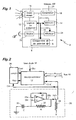
- FIG. 1 shows in the form of block diagram an electrical apparatus, said "slave module”, intended to establish or interrupt an electrical connection between two terminals 4, 6 at scheduled times of the day.
- a slave module 2 can be provided with a single pair of terminals 4, 6, as in the illustrated case, or several such pairs of terminals. In this In the latter case, different pairs of terminals can be programmed on periods independently of each other.
- the slave module 2 is managed by an associated processing logic 12 to a central memory 14.
- the latter has a fixed memory (ROM) containing data relating to the fixed aspects of the functioning of the device 2, for example the internal management codes of the various under control, and a random access memory (RAM) intended to receive inter alia programming data allowing the control of the block 8 free contact of potential based on data received from the outside, as will be described more far.
- ROM fixed memory
- RAM random access memory
- processing logic 12 and the central memory 14 operate in a known manner from binary signals clocked by means of a local oscillator.
- the programming data are downloaded by an infrared link by means of a receiving diode 16.
- This is a photodiode with integrated amplification with high immunity to light ambient, tuned to a frequency of the order of 950 nm and having a sensitivity of 0.2 to 0.4 milliwatt per square meter (mW / m 2 ).
- All of the aforementioned members 8-16 is powered by a unit of voltage output 18 connected externally to a low voltage network 20.
- the voltage output unit 18 may be constituted by a battery.
- the slave module 2 further comprises interface means with a user who, in the example, are constituted by a push-button switch 22 and, optionally, a display 24.
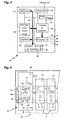
- FIG. 2 represents in simplified schematic form the part main processing logic 12, built around a microprocessor 12 'in accordance with a conventional architecture.
- the microprocessor 12 ' has a Din data entry which, in this case, is an input series type connected to the receiving diode 16, possibly via a circuit interface (not shown) for shaping the signals.
- the microprocessor 12 ' is furthermore connected to the bidirectional bus 10 in order to be able to exchange signals with the central memory 14 and with the block 8 free contact potential based on its internal management and data received from outside by means of the entrance Din.
- the microprocessor 12 ' is clocked by signals Sclk clock provided to a CLK input of the latter. These signals allow in particular to operate the internal logic of the microprocessor 12 ', which is synchronous type.
- Sclk clock signals are produced by an oscillator circuit specific 26 which can be either internal or external microprocessor 12 '.
- the oscillator is made from an ECL circuit (transmitter coupled logic) which includes an operational amplifier.
- the noninverting (positive) input 28a of the operational amplifier 28 is connected directly to the output 28b of the latter to form a positive loopback.
- the output 28b of the operational amplifier 28 is also looped back to the inverting (negative) input 28c of the latter through a resistor 30 of value R.
- the common node of the resistor 30 and the inverting input 28c is also connected to a frame of a capacitor 32 having a capacitance C.
- the other armature of capacitor 32 is connected to ground.
- the output 28b of the operational amplifier is biased to a negative voltage (for example - 5.2 volts) across a resistor 34 having a typical value of 3.9 kOhm.
- the frequency f of the oscillating signal Sclk, produced at the output 28b of the operational amplifier 28 is approximately 0.32 / RC.
- the values of R and C are chosen to give a frequency f of the order of 33 MHz.
- the microprocessor 12 ' is associated with a counting circuit 36 configured to form a time base from the Sclk signals of the oscillator 26.
- the counting circuit 36 has an input of counting Cin connected to the Sclk signal, and a Count output output that produces a pulse with a periodicity T for each number N of pulses of the Sclk signal totalized at the input Cin.
- T is equal to f / N.
- N is a value programmed according to the frequency f of the oscillator 26 of way that a pulse occurs regularly at the exit Cout at a predetermined time interval, for example once a minute or by fraction of a minute (for example every second).
- the microprocessor 12 receives the aforementioned pulses and exploits them to count the flow of time from a given reference. So, thanks to the pulses produced by the counting circuit 36, the microprocessor 12 'can fulfill a clock function recording the time, for example, time of day (hour, minutes, seconds, or time, minutes only).
- the microprocessor 12 comprises a reset output Raz, connected to a corresponding input of the counter 36, allowing the latter on the one hand to interrupt its count of N pulses in progress and on the other hand to simultaneously start counting N new pulses, and to continue to send a pulse after each count of N pulses.
- This reset function makes it possible in particular to resynchronize the counter 36, and hence the aforementioned clock, from a time signal outside received from the receive diode 16, as it will be detailed more far.
- the counter 36 is not necessarily a circuit physically separated from the microprocessor 12 '. It can indeed be integrated into microprocessor according to the availability of the internal functions of the latter. Of same, the clock function, ie the counting of time, can be performed outside the microprocessor 12 ', either by a specific circuit or by the counter 36.
- an important part of the base of time of the slave module 2 is constituted by the oscillator 26 which is intended for timing of the microprocessor 12 '. Thus, little - if not even - additional components are needed to implement this base of time.
- FIG. 3 is a simplified block diagram of a device 40 for input and transmission of programming and synchronization data, suitable for cooperate with the slave module 2 of FIGS. 1 and 2.
- This apparatus 40 which will be hereinafter referred to as "master module” or "inter-hourly post", is intended to establish transmit to each slave module 2 on the one hand data from programming and secondly temporal data allowing a resynchronization of their internal clock constituted by the oscillator assembly 26, the counter 36 and the microprocessor 12 '.
- the master module 40 has a processing logic 42 designed to manage the internal functions of the latter as well as the transmission of programming and synchronization data.
- This logic of treatment 42 is carried out according to a conventional architecture based on a microprocessor or a microcontroller. It is connected to a central memory 44 via a bus bidirectionnel 46.
- the central memory 44 includes a frozen memory (ROM) containing a fixed program for performing pre-established tasks for logic 42 and a programmable random access memory (RAM) for others to store variable programming data.
- ROM frozen memory
- RAM programmable random access memory
- the master module 40 also includes a time base 43 of accuracy greater than the time base of the slave module 2.
- the time base of the master module is made from a high oscillator Frequency, driven by quartz. It can be possibly associated with circuits of stabilization against temperature differences.
- the processing logic 42 and the central memory 44 are moreover connected, by means of the bidirectional bus 46, to a display device 48, a user interface 50 and a block 52 "potential free contact".
- the latter is functionally identical to the block 8 "free contact of potential "of Figure 1, and will not be described again for the sake of brevity.
- this block 52 also includes two terminals 54 and 56 functionally equivalent to terminals 4 and 6 of block 8.
- the module master 40 can also perform the same functions as a module slave 2.
- Programming and control of block 52 free contact of potential are substantially identical to those of the slave module 2, except that in this case it is possible to manage the activation and deactivation times of the block 52 directly from the clock 43 by wiring.
- the processing logic 42 is also connected to an interface of transmission of data which, in the example, is in the form of a infrared emission diode 58.
- the emission characteristics of this diode 58 are adapted to the receiving characteristics of the diode 16 of each slave module 2 which depends on the master module.
- the diode 58 emits at a wavelength of 950 nanometers (nm), under a power of 40 milliwatts per steradian (mW / sr) and at an emission angle of between 90 ° and 150 °, for example 120 °, the emission being done in pulsed mode to maximize the reach with acceptable power.
- All of the aforementioned active members is supplied with voltage by a power supply 59 connected to a low voltage network.
- a power supply 59 connected to a low voltage network.
- the master module being intended to be joined with one or more apparatuses 16 in an envelope common, as will be explained later.
- FIG. 4 represents a part of a group of slave modules 2 depending on a master module 40.
- the slave modules 2 (two of which only are represented) and the master module 40 are mounted so removable on rails 60 attached to the structure of an envelope 62.
- the latter can be a cabinet, a housing, or any other enclosure capable of integrating modular electrical appliances.
- the optical path between the diode transmitter 58 of the master module 40 and the receiver diodes 16 of the modules slaves 2 for the communication of programming data and synchronization comprises at least one reflection of the optical energy by a part of the envelope 62, for example the rear face 62a or elements of side wall, upper or lower.
- the diodes 58 and 16 are placed facing a reflective portion of the envelope, here the rear wall 62a.
- the communication does not depend on a direct aim of the module master 40 to the different slave modules 2. This arrangement allows to establish a communication with a slave module 2 wherever that is last, either on the same rail 60 as the master module 40, or on another rail.
- the display 48 of the master module 40 represented in FIG. 4 is a screen on the one hand a digital display 48a for present the hours and minutes corresponding either at the present time or at a reference time, and secondly segments 48b arranged in a circle representing a 24-hour dial.
- the segments of the dial can be activated (for example by being darkened) to display at least one schedule.
- the screen 48 further comprises one or more displays alphanumeric 48c which make it possible to visualize, among other things, a number assigned to a block 8, 52 potential-free contact belonging either to the module master 40, either to a slave module 2. This number, the role of which is described more far, may be specific to either a slave module 2 or a block 8, 52 in the where the device manages several blocks independently of each other.
- the user interface 50 has a set of buttons 64 to program time slots and set the time of the module 40.
- the programmed time slots correspond to periods during which a block 8, 52 potential-free potential contact is active, this belonging either to the master module 40 or to a slave module 2 of the assembly.
- the button 22 is accessible for set the latter to receive programming data.
- a first press on the button 22 of a module Slave 2 selected activates the data reception mode, and a second pressing this button deactivates this mode.
- a display (not shown), for example in the form of a light-emitting diode flashing light, indicating that the device is in programming. This display may possibly indicate a number assigned to the device.
- the activation of the data reception mode is done by a button 22 'on the front side.
- the programming consists in establishing, from the master module 40, the minus a time slot during which the block 8 potential-free contact of a slave module 2 selected must be activated.
- programming allows to transfer hourly data individually to different devices depending on the master module, the latter being able to also be for example time stamps associated with an event.
- the programming phase is activated from a "normal" mode of operation, in which the master module 40 as well as the modules Slaves 2 are in the execution configuration of a program.
- the initial state is first in the mode normal (step E70).
- the processing logic 12 then remains ready to detect a first pressing the button 22 (step E72). As soon as we press on it, the apparatus enters the programming mode (step E74).
- step E76 At the level of the master module 40, we start with the opening of the menu programming (step E76). It then appears on the display screen 48 a choice of modes, including channel programming mode. We select this mode (step E78) by one of the buttons 64 of the user interface 50 ( Figure 4). This action puts the master module 40 in the mode of programming itself.
- the master module displays on the screen 48 a channel number, which can be either imposed in a sequence by the processing logic 42 is selected by the user (step E80): the optional character of this step is indicated by the dotted lines that delimit the corresponding box of the organization chart.
- Assigning a channel number allows to register within the master module a one-to-one relationship between following programming data and the slave module 2 selected for receive these data.
- the channel number can be incremented by one unit after each complete programming cycle of one slave module 2, so as to automatically assign a new number channel to the next slave module 2 to be programmed.
- this number can be selected by the user.
- the channel number thus recorded in the master module 40 can be also registered at the corresponding slave module 2, in order to allow the user to identify later which of the slave modules 2 which corresponds to the programming data associated with a given channel.
- the registration of the channel number at the level of the slave modules 2 can be carried out by various means. It can be performed for example by affixing a label with the channel number on a visible part of each slave module, or by writing the number directly on it. In variant, we can consider transmitting the information relating to the channel as well as determined to the slave module 2 being programmed so that it records it internally and can, if necessary, display it, for example on the display 24.
- this programming involves entering one or more activation time slots of the block 8 potential-free contact of the slave module 2 selected. To this end, you first enter the hour and minute of the beginning of the first range to be programmed (step E82).
- this data is displayed for control on the screen 48 (step E84).
- the screen 48 displays for control the range corresponding timetable, for example in the form of segments activated on the 48 hours 48b display (step E88).
- the master module 40 goes into a detection configuration of a possible new time slot to be programmed for the same slave module 2, which can handle several different time slots.
- the master module 40 is automatically repositioned on the step of entering a new start time (step E82) - corresponding in this case to a second time programming range - if it does not detect not an order to send the programmed data (loopback b1). In this way, he is possible to record in the master module 40 a succession of ranges schedules by subsequently defining a concatenation of hours and minutes of beginning and end.
- step E90 the user controls the transmission of the data thus programmed to the slave module 2 having been previously activated to acknowledge and register these data in the aforementioned step E72 (step E90).
- This command is performed by pressing one of the buttons 64 of the user interface 50.
- the processing logic 42 of the master 40 command module the transmission of the programmed data by means of the infrared diode 58 (step E92) and exit channel programming mode (step E94).
- Those data are structured according to specific frames, called configuration frames, which will be described later with reference to FIG.
- step E96 the slave module 2 is in a message waiting phase (step E96) which is successive to the change to programming mode.
- the slave module 2 On receipt of the programming data, the slave module 2 stores them in the central memory 14 (step E98) so as to be able to use them in normal mode to govern over time the functions of its block 8 potential free contact.
- the slave module 2 then remains in the programming mode, for wait for the arrival of any other data frame to be recorded, until the programming mode within the device is deactivated by a second press of the button 22 (step E100).
- the slave module When this button is pressed for the second time (the first one being the aforementioned step E72), the slave module returns to the normal mode (loopback b2) in which it executes the program thus loaded.
- FIG. 6 schematically represents a configuration frame 110 as transmitted by the master module 40 to download the data of programming to the slave module 2.
- each time slot programmed gives rise to a corresponding configuration frame. So, in the case of a programming of n time slots for a slave module 2, that is to say when n-1 loopbacks b1 (FIG. 5) are carried out, n frames of configuration 110 are transmitted during the step E92 IR message transmission.
- the configuration frames 110 are transmitted as signals binary digits according to a pre-established protocol. In the example, each frame occupies 12 bytes.
- the master module 40 When the master module 40 is in normal operating mode, it transmits at regular intervals, for example every minute, data daily schedules and schedules to each of the slave modules 2 which depends on it. These daily data are developed from the internal time base 43 at master module 40.
- each slave module 2 can be periodically reset on a more precise time base to avoid major drifts in time, and on the other hand stay synchronized with each other.
- the daily and hourly data are transmitted in the form of frames, called "current frames".
- FIG. 7 schematically represents a current frame 112 transmitted by the master module 40 in normal operating mode.
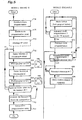
- step E120 We start with the setting of the slave module 2 in normal mode (step E120).
- the slave module 2 executes two routines in parallel: a first routine R1 for reading the current frames 112 in order to allow to resynchronize the internal clock and a second routine R2 of control of the 8 free potential contact block from the internal clock.
- These two routines R1 and R2 start from step 120 of setting in normal mode.
- Routine R1 begins with waiting for the next current frame 112 of the master module 40 (steps E122 and E124). As soon as a current frame 112 is received, this is transmitted from the receiving diode 16 to the processing logic 12 of each slave module 2. The data relating to the hour and the minutes - and possibly the data concerning the date - are read in the corresponding field (step E126) and used to resynchronize the internal clock (step E128). As explained above, this resynchronization is to reset the counter 36 (FIG. 2) and start again the measurement of the time by the internal clock of the module slave 2 from the new data provided by the current frame 112.
- the control routine R2 of the block 8 potential-free contact starts with setting the time according to the internal clock of the module slave (step E130).
- this step may include a calculation and / or conversion of a counting number of the counter 36 in hourly data in the same format as that used for recording of the programming data.
- the time established according to the internal clock is then compared with a start time of the time slot stored in the main memory 14 (step E132). If there is concordance, the block 8 potential-free contact is activated (step E134).
- step E136 the time established according to the internal clock is compared with a time of end of time slot stored in the central memory 14 (step E136). If there is a match, the 8 potential-free contact block is deactivated (step E138).
- the routine R2 then returns to the step E130 for setting the time according to the internal clock to repeat all of the steps E132 to E138.
- the internal time base of the slave module 2 essentially serves as a relay for temporal data from the master module 40.
- the control of the 8 free potential contact block is governed with high precision of the time base 43 of the master module 40, without it being necessary to physically achieve such a precise time base within of each slave module 2.
- the slave modules 2 can nevertheless perform their tasks programmed by referring to their internal timebase.
- the latter being used only as an auxiliary means, may be of design relatively simple and therefore less expensive than the module timebase master.
- the number of master and slave modules implemented in a installation is arbitrary. These modules can be grouped into one envelope, or distant from each other.
- programming frames and / or current frames can be carried out by any appropriate technical means: wired link, radio waves across the spectrum, or acoustic links.
- the action linked to a location in time can be other than activation and deactivation of contacts.
- This may include storage of time data, for example the time at which a event is detected within a slave module, which can be equipped one or more sensors of physical or electrical parameters: overvoltage detector (for example for a surge arrester function), smoke, burglary, temperature, lighting, anomaly on a system of data communication, etc.
Claims (25)
- Vorrichtung (2), welche dazu bestimmt ist, wenigstens eine Aktion, welche mit einer zeitlichen Markierung verbunden ist, durchzuführen, umfassend:wobei die Mittel zum Empfangen von zeitlichen Programmierdaten (110) und die Mittel zum Empfangen von Synchronisationsdaten (112) einen gemeinsamen Signalempfänger (16) umfassen;Mittel (12, 14, 16) zum Empfangen und Speichern von zeitlichen Programmierdaten (110), welche in Form von Signalen ausgesendet werden;Ausführungsmittel (12, 8), welche die Umsetzung einer mit einer zeitlichen Markierung verbundenen Aktion in Abhängigkeit von diesen zeitlichen Programmierdaten erlauben;Mittel (12, 14, 16) zum Empfangen von in Form von Signalen ausgesendeten Synchronisationsdaten (112), welche es erlauben, eine Synchronisierung mit einer externen Zeitreferenz (43) durchzuführen; undMittel zur Zeitmessung (12', 26, 36), welche von diesen Synchronisationsdaten referenziert sind und es erlauben, den Ausführungsmitteln (12, 8) eine zeitliche Markierung zu liefern;
wobei die Vorrichtung dadurch gekennzeichnet ist, dass sie des weiteren Mittel zum Versetzen in einen Programmiermodus umfassen, in dem die Mittel zum Empfangen und Speichern (12, 14, 16) von zeitlichen Programmierdaten (110) aktiv sind, und Mittel zum aus dem Programmiermodus setzen, in denen die Mittel zum Empfangen und Speichern von zeitlichen Programmierdaten inaktiv sind, wobei die Mittel zum Versetzen in den Programmiermodus und die Mittel zum Setzen aus diesem Programmiermodus eine Benutzerschnittstelle (22) umfassen. - Vorrichtung nach Anspruch 1,
dadurch gekennzeichnet, dass sie einen Oszillator (26) umfasst, welcher gleichzeitig als Signalquelle zur Taktversorgung der Ausführungsmittel (12, 8) und als periodische Signalquelle für die Mittel zur Zeitmessung (12', 26, 36) dient. - Vorrichtung nach Anspruch 2,
dadurch gekennzeichnet, dass sie Mittel (36) zum Zählen von Zyklen des periodischen Signals umfasst, welche die Berechnung der Entwicklung der Zeit in vorbestimmten Einheiten (beispielsweise Stunden und Minuten) ausgehend von zuvor gewonnenen Synchronisationsdaten erlaubt. - Vorrichtung nach einem der Ansprüche 1 bis 3,
dadurch gekennzeichnet, dass die Mittel zur Zeitmessung (12', 26, 36) so konfiguriert sind, dass sie sich bei jedem Empfang von Synchronisationsdaten (112) synchronisieren. - Vorrichtung nach einem der Ansprüche 1 bis 4,
dadurch gekennzeichnet, dass die Ausführungsmittel (8) Mittel zur Aktivierung und Deaktivierung von elektrischen Kontakten umfassen. - Vorrichtung nach Anspruch 5,
dadurch gekennzeichnet, dass die Ausführungsmittel (8) wenigstens einen Schalter umfassen, der das Öffnen und Schließen von elektrischen Kontakten erlaubt. - Vorrichtung nach einem der Ansprüche 1 bis 6,
dadurch gekennzeichnet, dass sie in Form eines Moduls (2) vorliegt, welches für eine lösbare Befestigung in einer Hülle (62) vorgesehen ist. - Vorrichtung nach einem der Ansprüche 1 bis 7,
dadurch gekennzeichnet, dass der Signalempfänger (16) empfindlich für infrarote Strahlung ist. - Vorrichtung nach Anspruch 8 zusammen mit Anspruch 7,
dadurch gekennzeichnet, dass das Empfangselement (16) in Richtung einer Wand (62a) der Hülle (62) gewandt ist, um eine von letzterer reflektierte Lichtenergie zu empfangen. - Vorrichtung nach einem der Ansprüche 1 bis 9,
dadurch gekennzeichnet, dass sie Mittel (24) zum Darstellen einer während einer Programmierphase etablierten Identität umfasst. - Vorrichtung (40), welche dazu bestimmt ist, zeitliche Programmierdaten (110) und Synchronisationsdaten (112) an eine Vorrichtung (2) gemäß einem der Ansprüche 1 bis 10 zu übertragen,
dadurch gekennzeichnet, dass sie umfasst:wobei diese Mittel zur Übertragung von Signalen, welche den zeitlichen Programmierdaten (110) entsprechen, und die Mittel zur Übertragung von Signalen, welchen den Synchronisationsdaten (112) entsprechen, einen gemeinsamen Signalsender (58) umfassen;Mittel (42 bis 50) zum Eingeben von zeitlichen Programmierdaten;Mittel (58) zum Erstellen und Übertragen von Signalen, welche den zeitlichen Programmierdaten entsprechen;Mittel, welche eine Uhr (43) bilden; undMittel (58) zum Erstellen und Übertragen von Signalen, die den Synchronisationsdaten entsprechen, ausgehend von Daten, welche von den eine Uhr bildenden Mitteln geliefert worden sind, wobei die Synchronisationsdaten in regelmäßigen Intervallen übertragen werden;
wobei die Vorrichtung so konfiguriert ist, dass sie über eine Auswahl mittels einer Benutzerschnittstelle (50) gemäß eines ersten Modus funktioniert, in dem sie aktiv ist, um das Eingeben von zeitlichen Programmierdaten und die Übertragung von Signalen, zu erlauben, welche den Programmierdaten (110) entsprechen, und gemäß eines zweiten Modus, in dem sie aktiv ist, um die Übertragung von Signalen zu erlauben, welche den Synchronisationsdaten (112) entsprechen. - Vorrichtung nach Anspruch 11,
dadurch gekennzeichnet, dass die Mittel (42 bis 50), welche das Eingeben von zeitlichen Programmierdaten (110) erlauben, so konfiguriert sind, dass sie es erlauben, eine Aufeinanderfolge von solchen Daten in einer Kette einzuführen, wobei die Gesamtheit von diesen für eine bestimmte Vorrichtung gemäß einem der Ansprüche 1 bis 10 bestimmt ist. - Vorrichtung nach einem der Ansprüche 11 oder 12,
dadurch gekennzeichnet, dass die zeitlichen Programmierdaten (110) wenigstens einen Wert umfassen, der sich auf einen Anfangsmoment einer Aktion bezieht und einen Wert, der sich auf einen Endmoment einer Aktion bezieht. - Vorrichtung nach einem der Ansprüche 11 bis 13,
dadurch gekennzeichnet, dass die zeitlichen Programmierdaten und die Synchronisationsdaten in Form von Rastern (jeweils 110, 112) erstellt sind, welche gemäß einer gemeinsamen Struktur in Feldern verteilt sind. - Vorrichtung nach einem der Ansprüche 11 bis 14,
dadurch gekennzeichnet, dass sie Mittel zum Speichern einer Identität einer Vorrichtung nach einem der Ansprüche 1 bis 10 umfasst, welche mit einer Programmierung verbunden sind, die dieser Vorrichtung zugeordnet ist. - Vorrichtung nach einem der Ansprüche 11 bis 15,
dadurch gekennzeichnet, dass die Synchronisationsdaten instantanen Zeiteinheiten entsprechen (beispielsweise Stunde, Minuten, Sekunden). - Vorrichtung nach einem der Ansprüche 11 bis 16,
dadurch gekennzeichnet, dass das Zeitintervall, welches aufeinanderfolgende Übertragungen von Synchronisationsdaten voneinander trennt, im Wesentlichen gleich einem Elementarschritt in der Auflösung der Programmierdaten ist. - Vorrichtung nach einem der Ansprüche 11 bis 17,
dadurch gekennzeichnet, dass sie des weiteren Mittel (42, 52) zum Ausführen einer Aktion in Abhängigkeit von diesen zeitlichen Programmierdaten umfasst. - Vorrichtung nach einem der Ansprüche 11 bis 18,
dadurch gekennzeichnet, dass sie in Form eines Moduls (40) vorliegt, welches für eine lösbare Befestigung in einer Hülle (62) vorgesehen ist. - Vorrichtung nach einem der Ansprüche 11 bis 19,
dadurch gekennzeichnet, dass der Signalsender (58) über eine Infrarotstrahlung sendet. - Vorrichtung nach Anspruch 20 kombiniert mit Anspruch 19,
dadurch gekennzeichnet, dass der Signalsender (58) in Richtung einer Wand (62a) der Hülle (62) gewandt ist, um in Richtung letzterer eine Lichtenergie zur Reflexion in Richtung wenigstens einer Vorrichtung nach einem der Ansprüche 1 bis 10 zu übertragen. - System zur Programmierung und Verwaltung von Aktionen, welche mit einer zeitlichen Markierung verbunden sind,
dadurch gekennzeichnet, dass es umfasst:wenigstens eine erste Vorrichtung (2) nach einem der Ansprüche 1 bis 10;wenigstens eine zweite Vorrichtung (40) nach einem der Ansprüche 11 bis 21; undVerbindungsmittel (62), welche es erlauben, eine Verbindung der ersten Vorrichtung mit der zweiten Vorrichtung herzustellen. - System nach Anspruch 22,
dadurch gekennzeichnet, dass diese Verbindung nur in eine Richtung wirksam ist. - System nach Anspruch 22 oder 23,
dadurch gekennzeichnet, dass die erste Vorrichtung (2) und die zweite Vorrichtung (40) in einer gemeinsamen Hülle (62) untergebracht sind. - Vorrichtung nach Anspruch 24,
dadurch gekennzeichnet, dass die Verbindung der ersten Vorrichtung (2) in Richtung der zweiten Vorrichtung (40) über einen optischen Weg realisiert ist, beispielsweise im infraroten Spektrum, mit einer Reflexion an wenigstens einer reflektierenden Oberfläche (62a) der gemeinsamen Hülle (62).
Applications Claiming Priority (3)
| Application Number | Priority Date | Filing Date | Title |
|---|---|---|---|
| FR0006446A FR2809217B1 (fr) | 2000-05-19 | 2000-05-19 | Appareils electriques et systeme destines a accomplir au moins une action liee a un reperage dans le temps |
| FR0006446 | 2000-05-19 | ||
| PCT/FR2001/001543 WO2001088645A1 (fr) | 2000-05-19 | 2001-05-18 | Appareils electriques et systeme destines a accomplir au moins une action liee a un reperage dans le temps |
Publications (2)
| Publication Number | Publication Date |
|---|---|
| EP1200883A1 EP1200883A1 (de) | 2002-05-02 |
| EP1200883B1 true EP1200883B1 (de) | 2005-11-09 |
Family
ID=8850424
Family Applications (1)
| Application Number | Title | Priority Date | Filing Date |
|---|---|---|---|
| EP01936590A Expired - Lifetime EP1200883B1 (de) | 2000-05-19 | 2001-05-18 | Elektrische vorrichtungen und system zur durchführung mindestens einer aktion zu einer vorbestimmten zeit |
Country Status (7)
| Country | Link |
|---|---|
| EP (1) | EP1200883B1 (de) |
| AU (1) | AU6246601A (de) |
| DE (1) | DE60114746T2 (de) |
| ES (1) | ES2248334T3 (de) |
| FR (1) | FR2809217B1 (de) |
| PL (1) | PL203945B1 (de) |
| WO (1) | WO2001088645A1 (de) |
Families Citing this family (2)
| Publication number | Priority date | Publication date | Assignee | Title |
|---|---|---|---|---|
| IT201600095427A1 (it) * | 2016-09-22 | 2018-03-22 | Finder Spa | Dispositivo interruttore orario perfezionato |
| CN111127869A (zh) * | 2019-12-30 | 2020-05-08 | 深圳市杰普特光电股份有限公司 | 工控设备及红外耦合触发方法 |
Family Cites Families (3)
| Publication number | Priority date | Publication date | Assignee | Title |
|---|---|---|---|---|
| GB2060953B (en) * | 1979-10-02 | 1983-08-10 | Central Electr Generat Board | Automatic synchronizing of time-pieces eg time switches by radio |
| AU6966196A (en) * | 1995-09-05 | 1997-03-27 | C. Eric Youngberg | System, method, and device for automatic setting of clocks |
| IT1291005B1 (it) * | 1997-01-13 | 1998-12-14 | Merloni Elettrodomestici Spa | Sistema di controllo per un apparato elettrodomestico. |
-
2000
- 2000-05-19 FR FR0006446A patent/FR2809217B1/fr not_active Expired - Fee Related
-
2001
- 2001-05-18 AU AU62466/01A patent/AU6246601A/en not_active Abandoned
- 2001-05-18 PL PL351789A patent/PL203945B1/pl not_active IP Right Cessation
- 2001-05-18 EP EP01936590A patent/EP1200883B1/de not_active Expired - Lifetime
- 2001-05-18 ES ES01936590T patent/ES2248334T3/es not_active Expired - Lifetime
- 2001-05-18 DE DE60114746T patent/DE60114746T2/de not_active Expired - Fee Related
- 2001-05-18 WO PCT/FR2001/001543 patent/WO2001088645A1/fr active IP Right Grant
Also Published As
| Publication number | Publication date |
|---|---|
| EP1200883A1 (de) | 2002-05-02 |
| AU6246601A (en) | 2001-11-26 |
| FR2809217B1 (fr) | 2003-10-24 |
| ES2248334T3 (es) | 2006-03-16 |
| DE60114746D1 (de) | 2005-12-15 |
| WO2001088645A1 (fr) | 2001-11-22 |
| DE60114746T2 (de) | 2006-07-06 |
| PL351789A1 (en) | 2003-06-16 |
| FR2809217A1 (fr) | 2001-11-23 |
| PL203945B1 (pl) | 2009-11-30 |
Similar Documents
| Publication | Publication Date | Title |
|---|---|---|
| EP0365402B1 (de) | Einrichtung zur Übertragung und Fernerfassung von Zählerdaten | |
| CA2036278C (fr) | Installation pour commander a distance l'affichage des prix dans un magasin | |
| FR2961055A1 (fr) | Reseau de balises lumineuses autonomes synchrones | |
| EP1200883B1 (de) | Elektrische vorrichtungen und system zur durchführung mindestens einer aktion zu einer vorbestimmten zeit | |
| FR2678755A1 (fr) | Telecommande a securite optimisee. | |
| EP0320390B1 (de) | Fernsteuereinrichtung für Haushaltsgeräte | |
| EP0064025B1 (de) | Elektronische Uhr mit unbewegbarer Steuervorrichtung | |
| EP0044232A1 (de) | Tragbarer digitaler Dosismesser zum Messen und Überwachen einer ionisierenden Strahlung | |
| EP0495322B1 (de) | Elektrisches Kontroll- und Steuerungssystem einer Funktionseinheit, insbesondere eines Hauses eines Gebäudes, eines Schiffes oder dergleichen | |
| EP0718730B1 (de) | Steuergerät zum Öffnen und Schliessen motorisierter Verdunklungsmittel, insbesondere Rolläden | |
| EP0068977A1 (de) | Verfahren zur Nachrichtenübertragung zwischen selbständigen Sende- und Empfangsmodulen welche unabhängige Taktgeber und interne Synchronisationseinrichtungen besitzen | |
| EP0065181A2 (de) | Verfahren zur elektronischen Identifikation | |
| FR2493552A1 (fr) | Compteur de temps numerique programmable et a fonction de chronodeclenchement | |
| FR2467946A1 (fr) | Serrure electronique a alarme | |
| FR2615306A1 (fr) | Systeme centralise de communication, a boitier portatif et reseau de terminaux fixes, notamment pour la teleidentification de personnes, boitier correspondant et procede de fonctionnement d'un tel systeme | |
| FR2598829A1 (fr) | Dispositif de commande domestique a usage general. | |
| EP1499154A1 (de) | Verfahren zur bidirektionalen Funkkommunikation zwischen mehreren Modulen eines Systemes | |
| FR2844084A1 (fr) | Telecommande pour capteur ou actionneur electronique | |
| FR2531587A1 (fr) | Procede pour la transmission d'informations sur un canal d'echanges unique et application de ce procede notamment a des dispositifs formant un systeme d'alarme | |
| FR2540648A1 (fr) | Systeme de programmation electronique, notamment pour installation de chauffage | |
| FR2547670A1 (fr) | Procede de controle des etats des issues d'un site et installation de surveillance d'un tel site | |
| WO2006048435A1 (fr) | Procede et dispositif de telecommande | |
| FR2623316A1 (fr) | Systeme de telecommande et de telesurveillance en temps partage | |
| WO2003044660A2 (fr) | Module et installation modulaire pour commander l'execution d'un programme | |
| FR2544564A1 (fr) | Recepteur de telecommande centralisee |
Legal Events
| Date | Code | Title | Description |
|---|---|---|---|
| PUAI | Public reference made under article 153(3) epc to a published international application that has entered the european phase |
Free format text: ORIGINAL CODE: 0009012 |
|
| 17P | Request for examination filed |
Effective date: 20020114 |
|
| AK | Designated contracting states |
Kind code of ref document: A1 Designated state(s): AT BE CH CY DE DK ES FI FR GB GR IE IT LI LU MC NL PT SE TR |
|
| AX | Request for extension of the european patent |
Free format text: AL;LT;LV;MK;RO;SI |
|
| RBV | Designated contracting states (corrected) |
Designated state(s): DE ES FR IT |
|
| 17Q | First examination report despatched |
Effective date: 20040901 |
|
| GRAP | Despatch of communication of intention to grant a patent |
Free format text: ORIGINAL CODE: EPIDOSNIGR1 |
|
| GRAS | Grant fee paid |
Free format text: ORIGINAL CODE: EPIDOSNIGR3 |
|
| GRAA | (expected) grant |
Free format text: ORIGINAL CODE: 0009210 |
|
| AK | Designated contracting states |
Kind code of ref document: B1 Designated state(s): DE ES FR IT |
|
| REF | Corresponds to: |
Ref document number: 60114746 Country of ref document: DE Date of ref document: 20051215 Kind code of ref document: P |
|
| REG | Reference to a national code |
Ref country code: ES Ref legal event code: FG2A Ref document number: 2248334 Country of ref document: ES Kind code of ref document: T3 |
|
| PLBE | No opposition filed within time limit |
Free format text: ORIGINAL CODE: 0009261 |
|
| STAA | Information on the status of an ep patent application or granted ep patent |
Free format text: STATUS: NO OPPOSITION FILED WITHIN TIME LIMIT |
|
| 26N | No opposition filed |
Effective date: 20060810 |
|
| REG | Reference to a national code |
Ref country code: FR Ref legal event code: CD |
|
| PGFP | Annual fee paid to national office [announced via postgrant information from national office to epo] |
Ref country code: ES Payment date: 20090522 Year of fee payment: 9 |
|
| PGFP | Annual fee paid to national office [announced via postgrant information from national office to epo] |
Ref country code: DE Payment date: 20090512 Year of fee payment: 9 Ref country code: FR Payment date: 20090427 Year of fee payment: 9 Ref country code: IT Payment date: 20090523 Year of fee payment: 9 |
|
| REG | Reference to a national code |
Ref country code: FR Ref legal event code: ST Effective date: 20110131 |
|
| PG25 | Lapsed in a contracting state [announced via postgrant information from national office to epo] |
Ref country code: IT Free format text: LAPSE BECAUSE OF NON-PAYMENT OF DUE FEES Effective date: 20100518 |
|
| PG25 | Lapsed in a contracting state [announced via postgrant information from national office to epo] |
Ref country code: DE Free format text: LAPSE BECAUSE OF NON-PAYMENT OF DUE FEES Effective date: 20101201 |
|
| PG25 | Lapsed in a contracting state [announced via postgrant information from national office to epo] |
Ref country code: FR Free format text: LAPSE BECAUSE OF NON-PAYMENT OF DUE FEES Effective date: 20100531 |
|
| REG | Reference to a national code |
Ref country code: ES Ref legal event code: FD2A Effective date: 20110714 |
|
| PG25 | Lapsed in a contracting state [announced via postgrant information from national office to epo] |
Ref country code: ES Free format text: LAPSE BECAUSE OF NON-PAYMENT OF DUE FEES Effective date: 20110704 |
|
| PG25 | Lapsed in a contracting state [announced via postgrant information from national office to epo] |
Ref country code: ES Free format text: LAPSE BECAUSE OF NON-PAYMENT OF DUE FEES Effective date: 20100519 |