EP1199616A2 - Zeitschaltvorrichtung insbesondere für Jalousien - Google Patents
Zeitschaltvorrichtung insbesondere für Jalousien Download PDFInfo
- Publication number
- EP1199616A2 EP1199616A2 EP01122067A EP01122067A EP1199616A2 EP 1199616 A2 EP1199616 A2 EP 1199616A2 EP 01122067 A EP01122067 A EP 01122067A EP 01122067 A EP01122067 A EP 01122067A EP 1199616 A2 EP1199616 A2 EP 1199616A2
- Authority
- EP
- European Patent Office
- Prior art keywords
- time
- switch
- timing device
- microprocessor
- opening
- Prior art date
- Legal status (The legal status is an assumption and is not a legal conclusion. Google has not performed a legal analysis and makes no representation as to the accuracy of the status listed.)
- Granted
Links
- 230000008859 change Effects 0.000 claims description 7
- 230000004913 activation Effects 0.000 claims description 6
- 238000012360 testing method Methods 0.000 claims description 6
- 238000003825 pressing Methods 0.000 claims description 4
- 238000009434 installation Methods 0.000 claims description 3
- 238000004804 winding Methods 0.000 claims description 3
- 239000004020 conductor Substances 0.000 claims description 2
- 238000012790 confirmation Methods 0.000 claims description 2
- 230000007935 neutral effect Effects 0.000 claims description 2
- 230000006870 function Effects 0.000 description 9
- 238000010586 diagram Methods 0.000 description 3
- 238000000034 method Methods 0.000 description 3
- 230000008569 process Effects 0.000 description 3
- 238000011156 evaluation Methods 0.000 description 2
- 230000001932 seasonal effect Effects 0.000 description 2
- 230000006978 adaptation Effects 0.000 description 1
- 230000000903 blocking effect Effects 0.000 description 1
- 239000003990 capacitor Substances 0.000 description 1
- 238000006243 chemical reaction Methods 0.000 description 1
- 230000003750 conditioning effect Effects 0.000 description 1
- 238000010276 construction Methods 0.000 description 1
- 230000009849 deactivation Effects 0.000 description 1
- 230000000694 effects Effects 0.000 description 1
- 238000005516 engineering process Methods 0.000 description 1
- 238000002955 isolation Methods 0.000 description 1
- 230000002441 reversible effect Effects 0.000 description 1
- 230000037072 sun protection Effects 0.000 description 1
- 230000036962 time dependent Effects 0.000 description 1
- 238000012546 transfer Methods 0.000 description 1
Images




Classifications
-
- G—PHYSICS
- G04—HOROLOGY
- G04G—ELECTRONIC TIME-PIECES
- G04G15/00—Time-pieces comprising means to be operated at preselected times or after preselected time intervals
- G04G15/006—Time-pieces comprising means to be operated at preselected times or after preselected time intervals for operating at a number of different times
Definitions
- the invention relates to a time switching device, in particular for opening and closing a blind using a limit switch controlled direction reversible motor, wherein one by means of input signals in a microprocessor current time, an on-switching time and an on-switching time are entered and by means of a clock generator
- the current actual time is saved in increments and on one Time display is shown and each time by a first comparison, the exceeding of the on-switching point is determined, the taxation takes place and each time when by a second comparison of exceeding the switch-on time is determined by the actual time, the control he follows.
- the solution is that the on-switching time and the on-switching time of a scaled input signal generator are fed to the microprocessor and the control and that Control for one up to one limit switch actuation sufficient period of time.
- the novel time switch device thus allows both at any time to change the timing and the timing by adjusting the signal generator.
- the setting is read on the scales.
- the setting ranges are expediently placed between 5 and 10 a.m. and 5 and 10 p.m.
- a Setting accuracy is of the order of 10 minutes sufficient for practical use.
- buttons are just two buttons, the one setting the clock and on the other hand overriding the set tax times serve. Setting the clock will by simultaneously pressing both buttons via one predetermined period initiated. A flashing control of the Time display shows readiness for operation. An actuation of the one or the other key then leads to an up or Counting down the time memory content. After a short Waiting time after the clock is set to standby leave and the flashing stops.
- the blind control is advantageous ended immediately when the button was released, so that Intermediate positions can be controlled as desired.
- the buttons controls of the blind control outputs advantageously also their control via external control means provided, the signals of the microprocessor not to Clock positions, however for immediate control in the same way as that Key control signals uses. This way too switch several timers virtually synchronously or on Use the brightness signal or the like for control.
- the requirements of On and off switching times are advantageous over Potentiometer signals made between their maximum signal levels and minimum signal level proportional to about thirty Signal ranges assigned to the respective scaled time range become.
- the potentiometer signals are sent via a multiplexer fed to an analog / digital converter. Because only about 32 values must be resolved by measuring the time using a simple ramp voltage of a timing element the digital signal can be obtained, which represents the analog signal.
- the potentiometers are advantageously approximately semicircular trained, with the opening potentiometer and the close potentiometer are located below.
- To be readable To enable scales and convenient operation are the Potentiometer operating lever arranged on the edge of a housing and inside of it the time display and the Provides buttons. The latter are again obvious to open up and below to close the blind or above to introduce and provided below for resetting the time.
- the zero position of the Input signal generator d. H. the position signal generator or Potentiometer, to be evaluated separately in the microprocessor in such a way that then no switch-on or switch-off time for comparison with the time is provided and therefore no corresponding Control signal is output.
- the rest of the adjustment range Input signal generator is expediently distributed over 5 hours, so that in the case of thirty partial areas, a resolution of the time default of 10 Minutes is reached.
- the construction of the device is advantageous in a flush-mounted block executed on which a cover plate similar to one Switch cover plate is mounted under which the input signal transmitter and switch contacts are mounted and by their Breakthroughs are sufficient on the setting levers of the input signal transmitters which pointers are aligned to the scales.
- the Keys are preferably attached to the cover plate with a film hinge hinged. In the middle is a breakthrough for the LCD clock display intended.
- the microprocessor In the flush-mounted block are the microprocessor, its power supply, the switching relays and a terminal block.
- One of the Relay expediently has a make contact, which is the mains phase line switches to a changeover contact of the second relay, its work and rest contact via the respective associated Limit switch of the blind drive to the direction connections of the Motors to be switched, between which a phase-shifting Reactance is arranged.
- Another advantageous embodiment is a panel-mounted version, which is preferred as a multiple control device is trained.
- this control device is for designed three blinds and thus exhibits six scaled Time setting means, e.g. B. potentiometer, and two for each blind associated relays on.
- Switch inputs are provided for one blind each.
- the entrances and outputs are operated in a multiplex program.
- the entire arrangement requires six standard module widths usual installation system.
- the clock display and the setting means of the clock are shared for all channels.
- buttons are also for a date and Advantageous to use weekday setting by the Date setting is initiated by a "date button", whereupon the date on the LCD display device during the setting process is given in the form of month and day.
- the currently set day of the week is expediently on an LED bar displayed with the appropriate caption.
- the saved date is used in conjunction with a corresponding program in a known manner a summer / - Winter time changeover.
- Another button "SU / WI" can be used by adjusting the actual time for each Activate Europe, USA, GB or to a manual changeover or switch an off state. The selected state is flashing briefly on the LCD display.
- the ongoing day of the week calculation and display is advantageous used by a weekend blocking function for each blind channel is introduced, each activated by pressing a button and is signaled on an LED display assigned to the channel and is deactivated by pressing another key.
- the weekend lock allows it to be used in one The automatic function on Saturday and Sunday for block individual channels.
- the Weekend lock function only suppresses the automatic function, manual control is always possible.
- Figure 1 shows a block diagram with the wiring of the Microprocessor (MP). This is on the input side with two Input signal transmitters, here potentiometers (P1, P2) connected, whose control signals via an input multiplexer (MPX) one Analog / digital conversion (A / D) are supplied. There are also two Buttons (TA, TZ) and two inputs for external signals (S1, S2) Digital inputs connected.
- a clock circuit (CL) controls the microprocessor chip's internal time counter.
- a time display LCD is connected on the output side as well two relays (R1, R2).
- One of the relays (R1) controls a make contact (AK), which the Mains phase (P) on a changeover contact (W) of the second relay (R2) switches, its work and break contact via terminals from the Switch block are brought out.
- These contact connections are in the In the case of blind control via an associated one Limit switch (EA, EZ) to the connections (MA, MZ) of the directional windings of the motor (M) connected, between which a capacitor (C) as a phase shifter connected.
- the mains neutral (N) is on the motor (M) and connected to a power supply (NT), which can also be connected to the Phase conductor (P) is connected.
- Figure 2 shows the top view of a flush-mounted device, the Cover plate (AP) carries all display and operating parts. In the middle is after a breakthrough placed the time display LCD and above and underneath there is an almost semicircular section introduced, in each of which an adjusting lever (H1, H2) with a Scale pointer is arranged on a time scale of Installation time (AS) or closing time (ZS) shows.
- the scales are with the hour names 5 to 10 or 17 - 22 labeled, and with an exhibition -OFF-.
- Figure 3 shows an exploded view of the front Components of the arrangement of Figure 2.
- the cover plate (AP) has the partially ring-shaped cutouts (D2, D3) with the scales (AS, ZS), the Key buttons (TAT, TZT) and the central breakthrough (D1) for the LCD display on.
- Locking webs are molded on the edge, which for Serve bracket of the unit in the flush-mounted box.
- each one of the Carry adjustment lever (H1, H2) on the front and on the back with a Sliding contact are provided, which on one of the signal transmitter, or potentiometer tracks (PB1, PB2) that grinds on the Contact plate (KP) are.
- PB1, PB2 potentiometer tracks
- KP potentiometer tracks
- This also carries connections (LCK) for the LCD display and for the key contacts (TK1, TK2) as well on the other hand connections for the microprocessor.
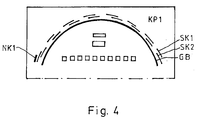
- Figure 4 shows half of an alternative contact plate (KP1), the instead of the potentiometer tracks with each other connected, angularly offset contacts (SK1, SK2), each through the contact grinder on the sliders (L1, L2) with the Basic contact path (GB) are connected and when adjusting give directional de / increment signals.
- KP1 potentiometer tracks with each other connected, angularly offset contacts
- SK1, SK2 angularly offset contacts
- L1, L2 the contact grinder on the sliders
- GB Basic contact path
- GB Basic contact path
- Figure 5 shows a functional diagram of the program of the microprocessor. Gate symbols are used, which are the logical ones Illustrate links between the signals and states. There are two interconnected complexes are shown, one of which the evaluation of the key operations and the other the evaluation concerns the input signals of the setting means.
- the two key signals (TA, TZ) are in their four states a key signal decoder (TDEC) decoded.
- TDEC key signal decoder
- a first time counter (Z1) is activated, the one Test time (PZ) of z. B. 3 seconds. Is the test time (PZ) expired and the two buttons (TA, TZ) are still a second time counter is activated, the one Clock period of z. B. 5 sec.
- a LCD flashing is controlled and with a clock signal (CL) ahead or Reset clock positions (CL +, CL-) is released as long as only one of the buttons (TA, TZ) is pressed.
- the control signals (CL +, CL-) are in a suitable place in the actual time counter (ISTT) fed in at the base entrance like the others Time counter is fed with the clock signals (CL), so that it Counts time of day.
- the second time counter (Z2) which counts the time setting period (UZ), always put on hold.
- the fourth counter is operated longer than the limit time (GZ) come to its final state, the exit to first relay (R1) and depending on the flag setting the output to the second relay (R2).
- GZ limit time
- a test is carried out for the automatic time-dependent control and conditioning the input signals (ES1, ES2) to determine whether they are not zero or the initial position is in which no automatic control should take place. Furthermore, each the determined position value of the input controller to a Time according to the scaling with a calibration (cal) standardized and in the associated memory of the switch-on time (AT) or switch-on time (ZT) loaded. Their content will be continuously with the actual time in the time counter (ISTT) with the associated comparisons (V1, V2) compared. Equality occurs and if the corresponding input signal (ES1, ES2) is not zero, then the flag (FF) is set accordingly and the fourth Time counter (Z4) activated, whereby the outputs to the relays (R1, R2) can be activated according to the flag setting.
- Figure 6 shows a panel-mounted device for three blind drive controls. There are two potentiometers each (P1 - P6) provided with scaled setting means and two Keys (11, 12; 21, 22; 31, 32) that the immediate or Serve direct control of the associated blind.
- the width of the Mounting block corresponds to six module widths in the standard system.
- buttons are used to set the time "clock symbol”, ("+”, "-") and "OK” in a known manner.
- the weekday display made of LED elements serves as a weekend lock function and the respective blind channel for the lock display another LED and if necessary. one associated key each (1-3).
- a “Date” key is used to enter a current date and an "SU / WI” button is used to select the type of switchover between the seasonal changes in various states or the Deactivation of the function.
- Figure 6 shows the front of a three-channel blind control device.
- the terminal assignment is in the List of reference symbols compiled.
- extension inputs are with each a push button (TE1, -TE6), each of which is a pair for opening and closing close to the associated blind (J1-J5) is arranged.
- Another pair of buttons (TP) serves one complete opening or closing of all blinds; it is preferably installed in a centrally accessible location.
- An example is a blind group (J3 - J5) with one each Isolation relay (TR) per blind on one output channel connected, so that a parallel operation up to individual limit switch.
Landscapes
- Physics & Mathematics (AREA)
- General Physics & Mathematics (AREA)
- Electric Clocks (AREA)
- Blinds (AREA)
Abstract
Description
Claims (21)
- Zeitschaltvorrichtung, insbesondere für das Auf- und Zusteuern einer Jalousie, mittels eines endschaltergesteuerten richtungsumsteuerbaren Motors (M), wobei mittels Eingabesignalen in einem Mikroprozessor (MP) jeweils eine aktuelle Uhrzeit, ein Auf-Schaltzeitpunkt (AT) und ein Zu-Schaltzeitpunkt (ZT) eingegeben sind und mittels eines Taktgebers (CL) die aktuelle Ist-Uhrzeit jeweils fortgezählt gespeichert und auf einer Uhrzeitanzeige dargestellt ist und jeweils, wenn durch einen ersten Vergleich (V1) die Überschreitung des Auf-Schaltzeitpunktes und auf einer Uhrzeitanzeige (LCD) dargestellt ermittelt ist, das Aufsteuern erfolgt und jeweils, wenn durch einen zweiten Vergleich (V2) die Überschreitung des Zu-Schaltzeitpunktes (ZT) durch die Ist-Uhrzeit ermittelt ist, das Zusteuern erfolgt, dadurch gekennzeichnet, daß Auf-Schaltzeitpunkt (AT) und der Zu-Schaltzeitpunkt (ZT) von jeweils einem skalierten Eingangsignalgeber (P1, P2) dem Mikroprozessor (MP) zugeführt sind und das Aufsteuern und das Zusteuern jeweils für einen bis zu einer Endschalterbetätigung ausreichenden Zeitraum (EBZ) erfolgt.
- Zeitschaltvorrichtung nach Anspruch 1, dadurch gekennzeichnet, daß die Eingabesignale für die Einstellung der aktuellen Uhrzeit durch zwei Tasten (TA, TZ) dem Mikroprozessor (MP) signalisiert werden, indem jeweils nachdem eine gleichzeitige Betätigung beider Tasten (TA, TZ) mindestens über einen vorgegebenen Prüfzeitraum (PZ) ermittelt worden ist, während eines Uhrstellzeitraumes beim Feststellen der Betätigung jeweils der einen oder anderen Taste (TA, TZ) ein schnelles Vor- oder Zurückstellen der aktuellen Uhrzeit erfolgt, und daß außerhalb des Uhrstellzeitraumes jeweils beim Feststellen einer Betätigung der einen Taste (TA) ein Aufsteuern erfolgt und jeweils beim Feststellen einer Betätigung der anderen Taste (TZ) ein Zusteuern erfolgt.
- Zeitschaltvorrichtung nach Anspruch 2, dadurch gekennzeichnet, daß jeweils wenn außerhalb des Uhrstellzeitraumes eine Betätigungsdauer einer der Tasten (TA, TZ) unterhalb eines Grenzzeitraumes (GZ) festgestellt worden ist, das Auf-oder Zusteuern für einen zu einer Endschalterbetätigung ausreichenden Zeitraum (EBZ) erfolgt und andernfalls das Auf-oder Zusteuern mit Beendigung der Tastenbetätigung endet.
- Zeitschaltvorrichtung nach einem der vorstehenden Ansprüche, dadurch gekennzeichnet, daß der ausreichende Zeitraum (EBZ) für die Endschalterbetätigung auf ca. 3 Minuten der Grenzzeitraum (GZ) auf ca. 400 ms, der Uhrstellzeitraum (UZ) ca. 5 sec. über eine Tastenbetätigung zur Uhrzeiteinstellung und der Prüfzeitraum auf ca. 3 sec. festgelegt sind.
- Zeitschaltvorrichtung nach einem der Ansprüche 2 bis 4, dadurch gekennzeichnet, daß während des Uhrstellzeitraumes die Uhrzeitanzeige (LCD) blinkend gesteuert ist.
- Zeitschaltvorrichtung nach einem der Ansprüche 2 bis 5, dadurch gekennzeichnet, daß parallel zu den Tasten (TA, TZ) wirkend externe Signalleitungen (S1, S2) an den Mikroprozessor (MP) angeschlossen sind.
- Zeitschaltvorrichtung nach einem der vorstehenden Ansprüche, dadurch gekennzeichnet, daß die Eingangssignalgeber (P1, P2) Potentiometer, digitale Positionscodegeber oder Incrementalcodegeber mit einer Nullstellungsmeldung, sind.
- Zeitschaltvorrichtung nach Anspruch 7, dadurch gekennzeichnet, daß die Endstellungsmeldungen jeweils keinen Auf-Schaltzeitpunkt (AT) oder Zu-Schaltzeitpunkt (ZT) signalisieren und die übrigen Positionswerte oder -codes jeweils 10-Minuten-Schritten zugeordnet sind und dem ersten Positionswert oder -code jeweils der Auf-Schaltzeitpunkt (AT) 5 Uhr bzw. der Zu-Schaltzeitpunkt (ZT) 17 Uhr zugeordnet und skaliert sind.
- Zeitschaltvorrichtung nach einem der vorstehenden Ansprüche, dadurch gekennzeichnet, daß jeweils wenn eine Änderung einer Einstellung eines Eingangssignalgebers (P1, P2) durch einen Vergleich (V3, V4) des neuen normierten Auf- oder Zuschaltzeitpunktes mit dem noch gespeicherten entsprechenden Auf- bzw. Zuschaltzeitpunkt (AT, ZT) ermittelt ist, dieser statt der Ist-Zeit der LCD-Anzeige für eine vorgegebene Zeit zur blinkenden Darstellung zugeführt ist.
- Zeitschaltvorrichtung nach einem der vorstehenden Ansprüche, dadurch gekennzeichnet, daß die Eingangssignalgeber (P1, P2) jeweils auf einem annähernd halbkreisförmigen Teilkreis angeordnet sind, innerhalb dessen die Uhrzeitanzeige (LCD) plaziert ist sowie jeweils eine der Tasten (TA, TZ) dem Auf-bzw. Zuschaltzeitgeber oberhalb bzw. unterhalb der Uhrzeitanzeige (LCD) zugeordnet angeordnet sind.
- Zeitschaltvorrichtung nach Anspruch 10, dadurch gekennzeichnet, daß die Tasten (TA, TZ) kreisabschnittförmig ausgebildet sind.
- Zeitschaltvorrichtung nach einem der Ansprüche 7 bis 11, dadurch gekennzeichnet, daß eine Kontaktplatte (KP) Anschlußpunkte (LCK) für die Uhrzeitanzeige (LCD), die Positionscodekontakte (PK1, PK2) oder Potentionsmeterbahnen (PB1, PB2) der Eingangssignalgeber (P1, P2), Schaltkontakte (TK1, TK2) der Tasten (TA, TZ) und Mikroprozessoranschlüsse trägt.
- Zeitschaltvorrichtung nach Anspruch 12, dadurch gekennzeichnet, daß sie zusammen mit Ausgangsschaltrelais (R1, R2) gekapselt an einem Unterputzeinbaurahmen montiert ist und über der Kontaktplatte (KP) eine äußere Abdeckplatte (AP) gehalten ist, die Durchbrüche (D1 - D3) für die Uhrzeitanzeige (LCD), Stellhebel (H1, H2) der Eingangssignalgeber (P1, P2) und deren Skalierungen (AS, ZS) sowie scharnierartig angelenkte Tastenknöpfe (TAT, TZT) der Tasten (TA, TZ) aufweist.
- Zeitschaltvorrichtung nach Anspruch 13, dadurch gekennzeichnet, daß die Stellhebel (H1, H2) mit konzentrischen Lagerringen (L1, L2) verbunden sind, die unter der Abdeckplatte (AP) verdrehbar gelagert sind und Schleifkontakte der analogen oder digitalen Eingangssignalgeber (P1, P2) tragen.
- Zeitschaltvorrichtung nach Anspruch 13, dadurch gekennzeichnet, daß eines der Ausgangsschaltrelais (R1) einen Wechselkontakt (W) betätigt und das andere einen Arbeitskontakt (AK) betätigt und ein Phasenanschluß (P) an den Arbeitskontakt (AK) gelegt ist und die geschaltete Phase an den Wechselkontakt (W) gelegt ist und dessen Arbeits- und Ruheanschlüsse jeweils mit einem Endschalter (EA, EZ) für eine Aufstellung bzw. Zustellung verbunden sind, zwischen deren abgehenden Kontakten eine Phasenschieberinpedanz (C) geschaltet ist und die jeweils an einen Motorwicklungsanschluß (MA, MZ) geführt sind, dessen Wicklungen andernends mit einem Nulleiter (N) verbunden sind.
- Zeitschaltvorrichtung nach einem der Ansprüche 1 bis 9, dadurch gekennzeichnet, daß an dem Mikroprozessor (MP) mehrere Paare von Eingangssignalgebern (P1 - P6) und Eingabetasten (11, 12; 21, 22; 31, 32) sowie externe Eingabeleitungen (El - E3) sowie Relais mit Ausgabeanschlüssen (A1 - A3) für das Auf- und Zusteuern angeschlossen sind und ein Programm diese in einem Multiplexbetrieb bedient.
- Zeitschaltvorrichtung nach Anspruch 16, dadurch gekennzeichnet, daß Eingangssignalgeber (P1, P2; -P6) Drehpotentiometer sind.
- Zeitschaltvorrichtung nach Anspruch 16 oder 17, dadurch gekennzeichnet, daß sie in ein Schalttafeleinbaugehäuse eingebaut ist und sechs Standard-Modulbreiten belegt.
- Zeitschaltvorrichtung nach einem der Ansprüche 16 bis 18, dadurch gekennzeichnet, daß für die Uhrzeiteingabe eine "Uhrzeit"-Taste, Auf- und Abzähltasten (+, -) und eine Bestätigungstaste (OK) an den Mikroprozessor (MP) angeschlossen sind, dessen Programm diese bedient.
- Zeitschaltvorrichtung nach einem der Ansprüche 16 bis 19, dadurch gekennzeichnet, daß an den Mikroprozessor (MP) eine Datum-Eingabetaste (DAT) und eine Sommerzeit/Winterzeitumschalttaste (SU/WI) angeschlossen sind und das Programm diese bedient, wobei während einer Datumseingabe dieses Datum für eine vorgegebene Zeit blinkend auf der LCD-Anzeige statt der Ist-Zeit dargestellt wird.
- Zeitschaltvorrichtung nach einem der Ansprüche 16 bis 20, dadurch gekennzeichnet, daß an den Mikroprozessor (MP) ausgangsseitig eine Wochentag-LED-Anzeigereihe angeschlossen ist, die programmäßig bedient wird und eine Stillegung der Zeitsteuerung der Ausgänge (A1 - A3) an den Wochenendtagen durch Tasteneingaben (1 - 3) eingebbar ist und auf zugehörigen LEDs angezeigt ist.
Applications Claiming Priority (2)
| Application Number | Priority Date | Filing Date | Title |
|---|---|---|---|
| DE2000151263 DE10051263A1 (de) | 2000-10-16 | 2000-10-16 | Zeitschaltvorrichtung insbesondere für Jalousien |
| DE10051263 | 2000-10-16 |
Publications (3)
| Publication Number | Publication Date |
|---|---|
| EP1199616A2 true EP1199616A2 (de) | 2002-04-24 |
| EP1199616A3 EP1199616A3 (de) | 2006-10-04 |
| EP1199616B1 EP1199616B1 (de) | 2008-12-10 |
Family
ID=7659981
Family Applications (1)
| Application Number | Title | Priority Date | Filing Date |
|---|---|---|---|
| EP20010122067 Expired - Lifetime EP1199616B1 (de) | 2000-10-16 | 2001-09-14 | Zeitschaltvorrichtung insbesondere für Jalousien |
Country Status (3)
| Country | Link |
|---|---|
| EP (1) | EP1199616B1 (de) |
| DE (2) | DE10051263A1 (de) |
| ES (1) | ES2317866T3 (de) |
Cited By (2)
| Publication number | Priority date | Publication date | Assignee | Title |
|---|---|---|---|---|
| FR2900191A1 (fr) * | 2006-04-24 | 2007-10-26 | Delta Dore | Procede de commande d'ouverture et de fermeture d'au moins un volet roulant ou d'au moins un groupe de volets roulants ou stores |
| EP1895371A3 (de) * | 2006-09-01 | 2009-11-25 | Theben AG | Zeitschaltuhr |
Citations (3)
| Publication number | Priority date | Publication date | Assignee | Title |
|---|---|---|---|---|
| EP0447849A1 (de) | 1990-03-20 | 1991-09-25 | elero Antriebs- und Sonnenschutztechnik Gmbh & Co. KG. | Elektronische Rolladensteuerung |
| EP0667440A1 (de) | 1994-02-15 | 1995-08-16 | Robert Bosch Gmbh | Vorrichtung zur elektronischen Steuerung der Bewegungen einer Verdunkelungsvorrichtung |
| DE19743098A1 (de) | 1997-09-30 | 1999-04-08 | Hans Arnhold | Zeitschaltuhr |
Family Cites Families (2)
| Publication number | Priority date | Publication date | Assignee | Title |
|---|---|---|---|---|
| FR2634915B1 (fr) * | 1988-07-29 | 1990-10-19 | Somfy | Installation de commande de plusieurs recepteurs electriques susceptibles d'occuper au moins deux etats |
| US6060852A (en) * | 1993-06-11 | 2000-05-09 | Harmonic Design, Inc. | Head rail-mounted actuator for window covering |
-
2000
- 2000-10-16 DE DE2000151263 patent/DE10051263A1/de not_active Withdrawn
-
2001
- 2001-09-14 EP EP20010122067 patent/EP1199616B1/de not_active Expired - Lifetime
- 2001-09-14 DE DE50114560T patent/DE50114560D1/de not_active Expired - Lifetime
- 2001-09-14 ES ES01122067T patent/ES2317866T3/es not_active Expired - Lifetime
Patent Citations (3)
| Publication number | Priority date | Publication date | Assignee | Title |
|---|---|---|---|---|
| EP0447849A1 (de) | 1990-03-20 | 1991-09-25 | elero Antriebs- und Sonnenschutztechnik Gmbh & Co. KG. | Elektronische Rolladensteuerung |
| EP0667440A1 (de) | 1994-02-15 | 1995-08-16 | Robert Bosch Gmbh | Vorrichtung zur elektronischen Steuerung der Bewegungen einer Verdunkelungsvorrichtung |
| DE19743098A1 (de) | 1997-09-30 | 1999-04-08 | Hans Arnhold | Zeitschaltuhr |
Cited By (2)
| Publication number | Priority date | Publication date | Assignee | Title |
|---|---|---|---|---|
| FR2900191A1 (fr) * | 2006-04-24 | 2007-10-26 | Delta Dore | Procede de commande d'ouverture et de fermeture d'au moins un volet roulant ou d'au moins un groupe de volets roulants ou stores |
| EP1895371A3 (de) * | 2006-09-01 | 2009-11-25 | Theben AG | Zeitschaltuhr |
Also Published As
| Publication number | Publication date |
|---|---|
| EP1199616A3 (de) | 2006-10-04 |
| EP1199616B1 (de) | 2008-12-10 |
| ES2317866T3 (es) | 2009-05-01 |
| DE50114560D1 (de) | 2009-01-22 |
| DE10051263A1 (de) | 2002-04-25 |
Similar Documents
| Publication | Publication Date | Title |
|---|---|---|
| DE69605375T2 (de) | Elektronische Zeitschalter | |
| EP0069046B1 (de) | Elektronisches Regelgerät | |
| DE4008940A1 (de) | Elektronische rolladensteuerung | |
| DE3032390C2 (de) | Elektrischer Uhrenthermostat | |
| EP0341443A1 (de) | Elektronische Digital-Zeituhr | |
| DE2358598A1 (de) | Elektronisches geraet mit einem zeitgeber | |
| DE2257064A1 (de) | Nachstelleinrichtung fuer eine digitaluhr | |
| DE2824510C2 (de) | Vorrichtung zum Steuern der Bewegung eines angetriebenen Tores | |
| EP0667440A1 (de) | Vorrichtung zur elektronischen Steuerung der Bewegungen einer Verdunkelungsvorrichtung | |
| DE3310344A1 (de) | Digitale schaltuhr | |
| EP1199616A2 (de) | Zeitschaltvorrichtung insbesondere für Jalousien | |
| EP0353625B1 (de) | Verfahren zur Bereichsauswahl am Bedienpult einer Druckmaschine, insbesondere einer Offset-Rotationsdruckmaschine | |
| DE19615150A1 (de) | Analoge Funkuhr mit Zeitzonen-Umschaltung | |
| DE3627894C2 (de) | ||
| DE7812259U1 (de) | Geraet zur raumtemperaturregelung | |
| EP0197336B1 (de) | Bedienungseinheit für eine Schaltuhr | |
| DE4419765A1 (de) | Heizungsregler | |
| EP0123729A1 (de) | Kombinationsgerät aus Rundfunkgerät und mindestens einem zusätzlichen elektronischen Gerät | |
| DE2804079A1 (de) | Programmierbarer elektrischer zeitschalter, insbesondere zur programmregelung eines thermostaten | |
| EP1353538A1 (de) | Programmierbarer Dämmerungsschalter | |
| EP0821295B1 (de) | Schaltgerät für die Ansteuerung eines Stellgliedes oder eines Verbrauchers | |
| DE9017816U1 (de) | Programmierbarer Heizungsregler | |
| DE3101861A1 (de) | "steuergeraet fuer eine raumheizungsanlage" | |
| EP0727722A2 (de) | Elektromechanische Herdschaltuhr | |
| DE2432390C3 (de) | Elektronisches Uhrwerk |
Legal Events
| Date | Code | Title | Description |
|---|---|---|---|
| PUAI | Public reference made under article 153(3) epc to a published international application that has entered the european phase |
Free format text: ORIGINAL CODE: 0009012 |
|
| AK | Designated contracting states |
Kind code of ref document: A2 Designated state(s): AT BE CH CY DE DK ES FI FR GB GR IE IT LI LU MC NL PT SE TR |
|
| AX | Request for extension of the european patent |
Free format text: AL;LT;LV;MK;RO;SI |
|
| RAP1 | Party data changed (applicant data changed or rights of an application transferred) |
Owner name: LEGRAND-BTICINO GMBH |
|
| PUAL | Search report despatched |
Free format text: ORIGINAL CODE: 0009013 |
|
| AK | Designated contracting states |
Kind code of ref document: A3 Designated state(s): AT BE CH CY DE DK ES FI FR GB GR IE IT LI LU MC NL PT SE TR |
|
| AX | Request for extension of the european patent |
Extension state: AL LT LV MK RO SI |
|
| AKX | Designation fees paid |
Designated state(s): DE ES FR IT |
|
| 17P | Request for examination filed |
Effective date: 20070524 |
|
| 17Q | First examination report despatched |
Effective date: 20070928 |
|
| GRAP | Despatch of communication of intention to grant a patent |
Free format text: ORIGINAL CODE: EPIDOSNIGR1 |
|
| GRAS | Grant fee paid |
Free format text: ORIGINAL CODE: EPIDOSNIGR3 |
|
| GRAA | (expected) grant |
Free format text: ORIGINAL CODE: 0009210 |
|
| AK | Designated contracting states |
Kind code of ref document: B1 Designated state(s): DE ES FR IT |
|
| REF | Corresponds to: |
Ref document number: 50114560 Country of ref document: DE Date of ref document: 20090122 Kind code of ref document: P |
|
| REG | Reference to a national code |
Ref country code: ES Ref legal event code: FG2A Ref document number: 2317866 Country of ref document: ES Kind code of ref document: T3 |
|
| PLBE | No opposition filed within time limit |
Free format text: ORIGINAL CODE: 0009261 |
|
| STAA | Information on the status of an ep patent application or granted ep patent |
Free format text: STATUS: NO OPPOSITION FILED WITHIN TIME LIMIT |
|
| 26N | No opposition filed |
Effective date: 20090911 |
|
| REG | Reference to a national code |
Ref country code: DE Ref legal event code: R082 Ref document number: 50114560 Country of ref document: DE Representative=s name: MARTIN BACKHAUS, DE |
|
| REG | Reference to a national code |
Ref country code: DE Ref legal event code: R082 Ref document number: 50114560 Country of ref document: DE Representative=s name: BACKHAUS, MARTIN, DIPL.-ING., DE Effective date: 20111207 Ref country code: DE Ref legal event code: R081 Ref document number: 50114560 Country of ref document: DE Owner name: LEGRAND GMBH, DE Free format text: FORMER OWNER: LEGRAND-BTICINO GMBH, 59494 SOEST, DE Effective date: 20111207 |
|
| REG | Reference to a national code |
Ref country code: FR Ref legal event code: CD Owner name: LEGRAND GMBH, DE Effective date: 20120109 |
|
| REG | Reference to a national code |
Ref country code: ES Ref legal event code: PC2A Owner name: LEGRAND GMBH Effective date: 20120214 |
|
| PGFP | Annual fee paid to national office [announced via postgrant information from national office to epo] |
Ref country code: ES Payment date: 20140923 Year of fee payment: 14 |
|
| PGFP | Annual fee paid to national office [announced via postgrant information from national office to epo] |
Ref country code: IT Payment date: 20140923 Year of fee payment: 14 |
|
| PGFP | Annual fee paid to national office [announced via postgrant information from national office to epo] |
Ref country code: FR Payment date: 20140917 Year of fee payment: 14 Ref country code: DE Payment date: 20141017 Year of fee payment: 14 |
|
| REG | Reference to a national code |
Ref country code: DE Ref legal event code: R119 Ref document number: 50114560 Country of ref document: DE |
|
| PG25 | Lapsed in a contracting state [announced via postgrant information from national office to epo] |
Ref country code: IT Free format text: LAPSE BECAUSE OF NON-PAYMENT OF DUE FEES Effective date: 20150914 |
|
| REG | Reference to a national code |
Ref country code: FR Ref legal event code: ST Effective date: 20160531 |
|
| PG25 | Lapsed in a contracting state [announced via postgrant information from national office to epo] |
Ref country code: DE Free format text: LAPSE BECAUSE OF NON-PAYMENT OF DUE FEES Effective date: 20160401 |
|
| PG25 | Lapsed in a contracting state [announced via postgrant information from national office to epo] |
Ref country code: FR Free format text: LAPSE BECAUSE OF NON-PAYMENT OF DUE FEES Effective date: 20150930 |
|
| PG25 | Lapsed in a contracting state [announced via postgrant information from national office to epo] |
Ref country code: ES Free format text: LAPSE BECAUSE OF NON-PAYMENT OF DUE FEES Effective date: 20150915 |
|
| REG | Reference to a national code |
Ref country code: ES Ref legal event code: FD2A Effective date: 20180710 |