EP1199497A2 - Method and device for controlling an automated gearbox - Google Patents
Method and device for controlling an automated gearbox Download PDFInfo
- Publication number
- EP1199497A2 EP1199497A2 EP01119388A EP01119388A EP1199497A2 EP 1199497 A2 EP1199497 A2 EP 1199497A2 EP 01119388 A EP01119388 A EP 01119388A EP 01119388 A EP01119388 A EP 01119388A EP 1199497 A2 EP1199497 A2 EP 1199497A2
- Authority
- EP
- European Patent Office
- Prior art keywords
- signal
- mode
- operating mode
- group
- selection
- Prior art date
- Legal status (The legal status is an assumption and is not a legal conclusion. Google has not performed a legal analysis and makes no representation as to the accuracy of the status listed.)
- Granted
Links
Images

Classifications
-
- F—MECHANICAL ENGINEERING; LIGHTING; HEATING; WEAPONS; BLASTING
- F16—ENGINEERING ELEMENTS AND UNITS; GENERAL MEASURES FOR PRODUCING AND MAINTAINING EFFECTIVE FUNCTIONING OF MACHINES OR INSTALLATIONS; THERMAL INSULATION IN GENERAL
- F16H—GEARING
- F16H59/00—Control inputs to control units of change-speed-, or reversing-gearings for conveying rotary motion
- F16H59/02—Selector apparatus
- F16H59/08—Range selector apparatus
-
- F—MECHANICAL ENGINEERING; LIGHTING; HEATING; WEAPONS; BLASTING
- F16—ENGINEERING ELEMENTS AND UNITS; GENERAL MEASURES FOR PRODUCING AND MAINTAINING EFFECTIVE FUNCTIONING OF MACHINES OR INSTALLATIONS; THERMAL INSULATION IN GENERAL
- F16H—GEARING
- F16H59/00—Control inputs to control units of change-speed-, or reversing-gearings for conveying rotary motion
- F16H59/02—Selector apparatus
- F16H59/0204—Selector apparatus for automatic transmissions with means for range selection and manual shifting, e.g. range selector with tiptronic
-
- F—MECHANICAL ENGINEERING; LIGHTING; HEATING; WEAPONS; BLASTING
- F16—ENGINEERING ELEMENTS AND UNITS; GENERAL MEASURES FOR PRODUCING AND MAINTAINING EFFECTIVE FUNCTIONING OF MACHINES OR INSTALLATIONS; THERMAL INSULATION IN GENERAL
- F16H—GEARING
- F16H59/00—Control inputs to control units of change-speed-, or reversing-gearings for conveying rotary motion
- F16H59/02—Selector apparatus
- F16H2059/0239—Up- and down-shift or range or mode selection by repeated movement
-
- F—MECHANICAL ENGINEERING; LIGHTING; HEATING; WEAPONS; BLASTING
- F16—ENGINEERING ELEMENTS AND UNITS; GENERAL MEASURES FOR PRODUCING AND MAINTAINING EFFECTIVE FUNCTIONING OF MACHINES OR INSTALLATIONS; THERMAL INSULATION IN GENERAL
- F16H—GEARING
- F16H2300/00—Determining of new ratio
- F16H2300/14—Selecting a state of operation, e.g. depending on two wheel or four wheel drive mode
-
- F—MECHANICAL ENGINEERING; LIGHTING; HEATING; WEAPONS; BLASTING
- F16—ENGINEERING ELEMENTS AND UNITS; GENERAL MEASURES FOR PRODUCING AND MAINTAINING EFFECTIVE FUNCTIONING OF MACHINES OR INSTALLATIONS; THERMAL INSULATION IN GENERAL
- F16H—GEARING
- F16H59/00—Control inputs to control units of change-speed-, or reversing-gearings for conveying rotary motion
- F16H59/36—Inputs being a function of speed
- F16H59/44—Inputs being a function of speed dependent on machine speed of the machine, e.g. the vehicle
-
- Y—GENERAL TAGGING OF NEW TECHNOLOGICAL DEVELOPMENTS; GENERAL TAGGING OF CROSS-SECTIONAL TECHNOLOGIES SPANNING OVER SEVERAL SECTIONS OF THE IPC; TECHNICAL SUBJECTS COVERED BY FORMER USPC CROSS-REFERENCE ART COLLECTIONS [XRACs] AND DIGESTS
- Y10—TECHNICAL SUBJECTS COVERED BY FORMER USPC
- Y10T—TECHNICAL SUBJECTS COVERED BY FORMER US CLASSIFICATION
- Y10T74/00—Machine element or mechanism
- Y10T74/19—Gearing
- Y10T74/19219—Interchangeably locked
- Y10T74/19251—Control mechanism
Definitions
- the invention relates to a device and a method for controlling an automatically switching Gearbox according to the categories of the independent claims.
- DE 43 11 886 A1 describes an apparatus and a method for controlling one automatically switching gear known in which the control from an automatic mode to a manual
- the operating mode changes when a position M is tapped with a gear selector switch or when using a shift rocker provided in the steering wheel for a predetermined period of time, for example 0.7 sec Switching signal is given.
- the manual operating mode is exited again when the Tap switch a position M is tapped again or for a predetermined period, for example 1.5 sec, an upshift signal is given.
- leaving the driver influenced operating mode can be provided if this operating mode is active for a predetermined period was. Overall, however, there is always a switch from automatic to manual Operating mode and vice versa.
- the value for the minimum dwell time should preferably be in the range of 25% of the time for manual Operating mode.
- a control device 1 shown in FIG. 1 controls an automatic transmission 2 and receives signals from a speed switch 3, a rocker switch 4 arranged on a steering wheel and a Throttle valve sensor 5, an engine speed sensor 6 and a vehicle speed sensor 7.
- the automatic transmission 2 receives a gear signal g from the control device 1 and sets it with the Gear signal g requested gear.
- the tap changer 3 has a first alley Operation of a first, automatic operating mode with the positions and speed levels P, R, N, D, 3, 2, 1 on. In the P position, the transmission is blocked on the output side for parking the vehicle. In the Position R is in reverse gear. No gear is engaged in position N. In position D the gear to be engaged g is determined from the operating parameters of the vehicle. Positions 3, 2 and 1 correspond to position D, but with the highest gear g to be engaged by Position of the speed switch 3 is determined. Positions 3, 2 and 1 are optional.
- step position D there is a designated M Recess provided.
- a selector lever provided as an operating element of the driving switch 3 snaps into place all positions.
- the rocker switch 4 is arranged on the steering wheel so that it is in the driver's grip area lies and has in addition to a neutral middle position two switching positions HS and RS, from which they automatically returns to the neutral center position after actuation.
- the two switch positions trigger a corresponding upshift signal HS or a downshift signal RS.
- the throttle valve sensor 5 supplies the control device 1 with a throttle valve signal a and the engine speed sensor 6 Engine speed signal n and the vehicle speed sensor 7 a vehicle speed signal v.
- the control device 1 has a first gear ratio determining device 8 for the first, automatic mode and a second translation determination device 9 for the second, from Driver-influenced operating mode and a differentiator 10.
- the first Transmission ratio determining device 8 receives the signals of the gear selector 3 and uses this to determine depending on the operating variables throttle signal a, engine speed signal n and Vehicle speed signal v the gear stage to be engaged, which it then transmits in the form of the gear stage signal g transmits the transmission 2.
- the second gear ratio determining device 9 receives the switching signals HS / RS of the rocker switch 4 and from this generates the gear level signal g, the operating variables Throttle valve signal a, engine speed signal n, vehicle speed signal v for plausibility checks and Safety measures such as overturn protection, chipping protection and the like are used.
- the Gear stage signal g is only generated with the falling edge of the switching signal HS / RS, i.e. when you release the Shift paddle 4 delivered.
- the differentiating device 10 evaluates the signals of the gear selector 3 and the rocker switch 4 and thereafter determines whether the first gear determining device 8 or the second Translation determination device 9 is activated.
- a first one Signal evaluation device 11 is with the speed switch 3 and a second signal evaluation device 12 connected to the rocker switch 4.
- the output signals of the signal evaluation devices 11, 12 are closed a switching device 13, which in turn either the first translation determination device 8 or the second transmission determination device 9, but never both at the same time, activated.
- an input AUT and an input MAN are provided on the switching device 13.
- a signal at the AUT input triggers the switchover device, the first transmission determination device 8 to activate and thus to select the automatic operating mode.
- a signal at the MAN input activates the second gear ratio determination device 9 and selects that from the driver (by means of the rocker switch 4) influenced operating mode.
- Both inputs MAN and AUT can accept several signals and these too if necessary link logically with each other.
- the first signal evaluation device 11 recognizes from the evaluation of the signal of the tap changer 3, whether it is in the M position. If this is the case, it sends a signal to the MAN input Switching device 13, so that the operating mode influenced by the driver is now selected. Recognize the first Signalausnce -cardill that the speed switch 3 is no longer in the M position, so it gives a signal to the AUT input of the switching device 13 and thus selects the automatic one Mode. Overall, the switching device 13 makes the first Gear ratio determining device 8 is activated as long as the speed switch 3 is in position D is located, and the second translation determination device 9 is activated as long as the Speed switch 3 is in the M position.
- the second signal evaluation device 12 evaluates the signal of the rocker switch 4 in such a way that it checks whether an upshift signal HS or a downshift signal RS is present. If this is the case, then an AND gate is used 14 emitted a signal. The other input of the AND gate 14 is with an output of the first Signal detection device 11 connected, which emits a signal when the tap changer 3 in the Position D is.
- the output of the AND gate 14 is guided to a delay element 15, which is a switch-off delay with programmable duration t.
- the output of the delay element 15 is connected to the input MAN the switching device 13 connected.
- the delay element 15 receives at a reset input R. furthermore a signal kd of a kick-down switch 16. If such a signal kd is present on the delay element 15, the delay element 15 is immediately reset and no longer emits a signal.
- An AND gate is between the delay element 15 and the input MAN of the switching device 13 30 provided, the second input receives a signal from a second delay element 31 that includes a switch-off delay with the programmable duration t2.
- the second delay 31 receives the signal of an AND gate 32, which signals aqg of a lateral acceleration limit switch 17 and zs of a train-thrust detector 18 linked together.
- the lateral acceleration limit value transmitter 17 emits the signal aqg when the amount of the Lateral acceleration exceeds a preset value aqmax.
- the train-push detector 18 gives that Signal zs off when there is overrun.
- the duration t2 is here in the size of 25% of the duration t des Delay element 15 selected.
- the second delay element 31 also receives R at a reset input a signal kd of a kick-down switch 16.
- the vehicle is in the automatic mode operated, i.e. the gearbox to be engaged is automatically determined by the vehicle's operating parameters determined and set.
- the driver wishes to switch to the second one influenced by him Operating mode, he moves the speed switch 3 from position D to position M.
- the Trigger upshifts or downshifts via the rocker switch 4 in the steering wheel by pressing the Shift rocker actuated in the sense of an upshift or in the sense of a downshift.
- a shift is triggered even without a shift command from the driver Bring the vehicle back to the permissible operating limits.
- the driver can briefly switch to the second operating mode influenced by him he in position D of the tap changer 3 an upshift or a downshift via the rocker switch 4th requests.
- the changeover follows the requested circuit performed because the signal of the rocker switch 4 at the second Ratio determination device 9 is pending (triggering of the gear stage signal g with the negative Flank of the switching signals HS / RS).
- the first, automatic operating mode is automatically selected again when the programmed duration t after the switching signal HS or RS has expired and both the amount of lateral acceleration below of a predetermined limit value and there is no overrun operation. If during the duration this brief call of the second operating mode influenced by the driver, a signal kd of a kick-down switch 16 is present, the first automatic mode is selected again immediately. But will during the brief call of the times, overrun mode influenced by the driver recognized or if the amount of lateral acceleration exceeds the specified limit, then the Delay element 34 ensures that if a change to the first operating mode is possible again is, the second operating mode can only be exited after the period t2.
- the control device 1 can of course also be designed in the form of a microcomputer. On such a microcomputer works according to a method created according to the method described below Program.
- the control device 1 first controls this with a group of steps, not shown Transmission 2 in the first, automatic operating mode, according to the operating parameters Throttle valve signal a, engine speed signal n and vehicle speed signal v using stored Maps determines the gear to be engaged and a request for this gear the transmission 2 outputs.
- the signal of the rocker 4 is queried.
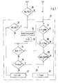
- the in Fig. Step 20 shown in FIG. 3 is part of this query.
- step 20 it is checked whether the rocker switch 4 an upshift or a downshift signal HS / RS has been issued. If this is not the case, the remains Control device 1 in its automatic operating mode, here characterized by the drive level D. Is on the other hand, an upshift or downshift signal HS / RS on, the program becomes manual Short-term influence 21 branches.
- the program 21 begins in its first step 22 with the execution of the upshift or Downshift signal HS / RS requested circuit.
- This first step 22 is an alternative Execution of the method is not provided if the program 21 by a first upshift or Downshift signal HS / RS is initially only to be called without immediately switching is performed.
- a time counter T is reset to the value zero.
- step 24 a kick-down signal kd is requested. If there is such a signal, it becomes Ascent routine 25 branches. Otherwise, the program continues with step 26, where checks are made is whether the counter T has reached its maximum value - here corresponding to a period of 8 seconds. If the maximum value is reached or exceeded, a branch is also made to the ascent routine 25 and otherwise the program continues with step 27 by increasing the time counter T by a time increment dT becomes.
- step 28 it is again checked whether an upshift or downshift signal HS / RS is present. If this is the case, the program flow continues with step 22, while otherwise directly branch to step 24.
- the exit routine 25 consists of three test steps 29 to 31.
- the first test step 29 it is checked whether the signal aqg for the lateral acceleration of the vehicle is less than a preset maximum value aqmax is.
- the signal ZS indicates a train operation of the vehicle.
- step 31 it is checked in step 31 whether the driving speed v of the vehicle is greater than one
- the minimum value vmin from here is 5 km / h.
- step 29 to 31 If the conditions checked in steps 29 to 31 are all met, program 21 is exited. If, on the other hand, one of the three conditions is not met, the time counter T is changed to the value Tmin in step 32 set, which in the present example is a size of 75% of the maximum value checked in step 26 accepts.
- the signal zs of the pull-push detector 18 assumes the value "thrust" when the vehicle is stationary or at low speed (less than 5 km / h) rolls. In normal driving operation, however, the signal zs acts in a manner known per se the position of the throttle valve DK or determined using alternative methods. This results in the Steps 30, 31 the effect that the program 21 with a stationary or rolling vehicle and not accelerator pedal cannot be exited. This makes it possible, for example, to first gear to select as starting gear by actuating the rocker switch 4, while in gear D in automatic mode, the second gear is regularly used as the starting gear.
Landscapes
- Engineering & Computer Science (AREA)
- General Engineering & Computer Science (AREA)
- Mechanical Engineering (AREA)
- Control Of Transmission Device (AREA)
Abstract
Description
Die Erfindung betrifft eine Vorrichtung und ein Verfahren zum Steuern eines selbsttätig schaltenden Getriebes nach den Gattungen der unabhängigen Ansprüche.The invention relates to a device and a method for controlling an automatically switching Gearbox according to the categories of the independent claims.
Um dem Fahrer eines Fahrzeuges in besonderen Situationen auch bei selbsttätig schaltenden Getrieben die
Möglichkeit der direkten Beeinflussung der gewählten Übersetzung zu geben, ist es aus der DE-Z
"Automobiltechnische Zeitschrift" Heft 6/1990, Seite 308 bis 319 bekannt, neben einem Automatikbetrieb
einen Manuellbetrieb vorzusehen, in dem der Fahrer einzelne Gänge des Stufenautomaten direkt anwählen
kann. Zu diesem Zweck ist parallel zu einer Schaltgasse für den Automatikbetrieb eine zweite Schaltgasse
für den manuellen Betrieb vorgesehen, in der der Fahrer durch eine wippenartige Bewegung eines
Schalthebels jeweils eine Rück- oder Hochschaltung um einen Gang veranlassen kann. Eine ähnliche
Vorrichtung für stufenlose Getriebe ist aus der CH-Z "Automobil Revue" Heft 51/1992, Seite 23, bekannt.To the driver of a vehicle in special situations even with automatically shifting transmissions
To give the possibility to directly influence the selected translation, it is from DE-Z
"Automobiltechnische Zeitschrift"
Darüber hinaus ist es bekannt, Gangwechsel in einem fremdkraftbetätigten Getriebe durch eine
Wähleinrichtung von einem Lenkrad eines Fahrzeuges aus zu veranlassen (beispielsweise DE-Z "Auto Motor
Sport" Heft 22/1991, Seite 300).In addition, it is known to change gear in a power-operated transmission through a
To initiate selection device from a steering wheel of a vehicle (for example DE-Z "Auto Motor
Sport "
Außerdem ist aus der DE 43 11 886 A1 eine Vorrichtung und ein Verfahren zum Steuern eines selbsttätig schaltenden Getriebes bekannt, bei der die Steuerung von einer automatischen Betriebsart in eine manuelle Betriebsart wechselt, wenn mit einem Fahrstufenschalter eine Stellung M angetippt wird oder wenn mittels einer im Lenkrad vorgesehenen Schaltwippe für einen vorgegebenen Zeitraum, beispielsweise 0,7 sec, ein Schaltsignal abgegeben wird. Die manuelle Betriebsart wird wieder verlassen, wenn mit dem Fahrstufenschalter eine Stellung M erneut angetippt wird oder für einen vorgegebenen Zeitraum, beispielsweise 1,5 sec, ein Hochschaltsignal gegeben wird. Schließlich kann ein Verlassen der vom Fahrer beeinflussten Betriebsart vorgesehen sein, wenn diese Betriebsart über einen vorgegebenen Zeitraum aktiv war. Insgesamt handelt es sich jedoch stets um eine Umschaltung von der automatischen in die manuelle Betriebsart und umgekehrt.In addition, DE 43 11 886 A1 describes an apparatus and a method for controlling one automatically switching gear known in which the control from an automatic mode to a manual The operating mode changes when a position M is tapped with a gear selector switch or when using a shift rocker provided in the steering wheel for a predetermined period of time, for example 0.7 sec Switching signal is given. The manual operating mode is exited again when the Tap switch a position M is tapped again or for a predetermined period, for example 1.5 sec, an upshift signal is given. Finally, leaving the driver influenced operating mode can be provided if this operating mode is active for a predetermined period was. Overall, however, there is always a switch from automatic to manual Operating mode and vice versa.
Aus der DE 199 12 963 A1 ist bereits eine Vorrichtung und ein Verfahren zum Steuern eines selbsttätig schaltenden Getriebes bekannt, bei der die Steuerung von der in einer Stellung D eines Fahrstufenschalters normalerweise gewählten automatischen Betriebsart ohne Auswahl durch die erste Wähleinrichtung zeitweise in die vom Fahrer beeinflusste Betriebsart wechselt, wenn eine zweite am Lenkrad angeordnete Schaltwippe betätigt wird. Hiermit wird die automatischen Betriebsart nicht dauerhaft verlassen, denn nach Ablauf einer eingestellten Zeitdauer wird wieder die automatische Betriebsart aktiv. Die Zeitdauer beginnt mit jeder Betätigung der Schaltwippe von neuem zu laufen. Eine Rückkehr in die automatische Betriebsart ist nur dann möglich, wenn die aktuelle Querbeschleunigung unterhalb eines vorgegebenen Grenzwertes liegt und gleichzeitig Zugbetrieb herrscht.DE 199 12 963 A1 has already disclosed an apparatus and a method for controlling one switching gearbox known, in which the control of the in a position D of a tap changer normally selected automatic mode without selection by the first selection device temporarily changes to the operating mode influenced by the driver if a second one is arranged on the steering wheel Shift rocker is operated. This does not leave the automatic operating mode permanently, because after The automatic operating mode becomes active again after a set period of time. The period begins run again each time the rocker switch is pressed. A return to automatic mode is only possible if the current lateral acceleration is below a specified limit and there is train operation at the same time.
Es ist Aufgabe der Erfindung, eine Vorrichtung und ein Verfahren zu schaffen, das hinsichtlich seiner Fahrbarkeit weiter verbessert ist.It is an object of the invention to provide an apparatus and a method which with regard to its Drivability is further improved.
Dies Aufgabe wird erfindungsgemäß mit den Merkmalen der unabhängigen Ansprüche gelöst. Es wird vorgeschlagen, nach einer kurzzeitigen Anwahl der zweiten, vom Fahrer beeinflussten Betriebart die verbleibende Zeitdauer vor einer Rückkehr in die automatische Betriebart auf einen Mindestwert zu setzen, sobald eine der genannten Bedingungen, bei der eine Rückkehr in die automatische Betriebsart unterdrückt wird, nicht weiter vorliegt. In vorteilhafter Weise ist hiermit erreicht, dass nach Wegfallen einer der genannten Bedingungen nicht unmittelbar eine Rückkehr in die automatische Betriebsart erfolgt, sondern eine Mindest-Verweildauer in der manuellen Betriebsart gewährleistet ist. Der Erfindung liegt dabei die Erkenntnis zu Grunde, dass die Fahrzustände, die auch nach Ablauf der vorgegebenen Zeitdauer in der manuellen Betriebsart zu einem weiteren Verbleib in der manuellen Betriebsart führen kurzzeitig unterbrochen werden können, ohne dass hiermit gleichzeitig eine Notwendigkeit für den Wechsel in die automatische Betriebsart gegebene wäre. Insgesamt wird das Schaltverhalten des Getriebes und insbesondere die Wahl seiner Betriebsart damit für den Fahrer hinsichtlich der Vorhersehbarkeit und der Überschaubarkeit verbessert. Die Art der genannten Bedingungen für eine Rückkehr in die automatische Betriebsart ist hier nicht von Bedeutung, solange diese Bedingungen besondere Fahrzustände anzeigen.This object is achieved with the features of the independent claims. It will suggested that after a brief selection of the second operating mode influenced by the driver set the remaining time before a return to the automatic mode to a minimum value, as soon as one of the conditions mentioned, in which a return to the automatic mode is suppressed is no longer available. It is hereby advantageously achieved that after one of the conditions mentioned does not immediately return to the automatic operating mode, but instead a minimum dwell time in the manual operating mode is guaranteed. The invention lies in the Underlying knowledge that the driving conditions, even after the specified period of time in the manual operating mode lead to a further remaining in the manual operating mode for a short time can be interrupted without the necessity to switch to the automatic operating mode would be given. Overall, the shift behavior of the transmission and in particular the choice of its operating mode for the driver with regard to predictability and Manageability improved. The type of conditions mentioned for a return to automatic Operating mode is not important here as long as these conditions indicate special driving conditions.
Der Wert für die Mindest-Verweildauer soll vorzugsweise im Bereich von 25% der Zeitdauer für die manuelle Betriebsart liegen.The value for the minimum dwell time should preferably be in the range of 25% of the time for manual Operating mode.
Die Verfahrensansprüche teilen die Wirkungen und Vorteile der entsprechenden Vorrichtungsansprüche.The process claims share the effects and advantages of the corresponding device claims.
Die Erfindung ist nachstehend anhand eines in den Zeichnungen dargestellten Ausführungsbeispieles beschrieben. Es zeigen:
- Fig. 1
- eine erfindungsgemäße Steuervorrichtung,
- Fig. 2
- eine Umschalteinrichtung der Steuervorrichtung und
- Fig. 3
- ein Flussdiagramm des erfindungsgemäßen Verfahrens.
- Fig. 1
- a control device according to the invention,
- Fig. 2
- a switching device of the control device and
- Fig. 3
- a flowchart of the method according to the invention.
Eine in Fig. 1 gezeigte Steuervorrichtung 1 steuert ein automatisches Getriebe 2 und erhält Signale von
einem Fahrstufenschalter 3, einer an einem Lenkrad angeordneten Schaltwippe 4 sowie einem
Drosselklappengeber 5, einem Motordrehzahlgeber 6 und einem Fahrgeschwindigkeitsgeber 7.
Das automatische Getriebe 2 erhält von der Steuervorrichtung 1 ein Gangsignal g und legt den mit dem
Gangsignal g angeforderten Getriebegang ein. Der Fahrstufenschalter 3 weist eine erste Gasse zur
Bedienung einer ersten, automatischen Betriebsart mit den Stellungen und Fahrstufen P, R, N, D, 3, 2, 1
auf. In der Stellung P ist das Getriebe zum Abstellen des Fahrzeuges ausgangsseitig blockiert. In der
Stellung R ist ein Rückwärtsgang eingelegt. In der Stellung N ist kein Gang eingelegt. In der Stellung D wird
der einzulegende Getriebegang g aus Betriebsparametern des Fahrzeuges bestimmt. Die Stellungen 3, 2
und 1 entsprechen der Stellung D, wobei jedoch der höchste einzulegende Getriebegang g durch die
Stellung des Fahrstufenschalters 3 bestimmt ist. Die Stellungen 3, 2 und 1 sind optional.A
Ausgehend von dieser ersten Gasse ist gegenüberliegend der Stufenstellung D eine mit M bezeichnete
Ausnehmung vorgesehen. Ein als Bedienelement des Fahrschalters 3 vorgesehener Wählhebel rastet in
allen Stellungen ein. Die Schaltwippe 4 ist so am Lenkrad angeordnet, dass sie im Griffbereich des Fahrers
liegt und weist neben einer neutralen Mittelstellung zwei Schaltstellungen HS und RS auf, aus denen sie
nach Betätigung wieder selbsttätig in die neutrale Mittelstellung zurückkehrt. Die beiden Schaltstellungen
lösen ein entsprechendes Hochschaltsignal HS bzw. ein Rückschaltsignal RS aus. Der Drosselklappengeber
5 liefert der Steuervorrichtung 1 ein Drosselklappensignal a, der Motordrehzahlgeber 6 ein
Motordrehzahlsignal n und der Fahrgeschwindigkeitsgeber 7 ein Fahrgeschwindigkeitssignal v.Starting from this first lane, opposite to step position D, there is a designated M
Recess provided. A selector lever provided as an operating element of the
Die Steuervorrichtung 1 weist eine erste Übersetzungsbestimmungseinrichtung 8 für die erste,
automatische Betriebsart und eine zweite Übersetzungsbestimmungseinrichtung 9 für die zweite, vom
Fahrer beeinflusste Betriebsart sowie eine Unterscheidungseinrichtung 10 auf. Die erste
Übersetzungsbestimmungseinrichtung 8 erhält die Signale des Fahrstufenschalters 3 und bestimmt hieraus,
abhängig von den Betriebsgrößen Drosselklappensignal a, Motordrehzahlsignal n und
Fahrgeschwindigkeitssignal v die einzulegende Gangstufe, die sie dann in Form des Gangstufensignals g an
das Getriebe 2 weitergibt. Die zweite Übersetzungsbestimmungseinrichtung 9 empfängt die Schaltsignale
HS/RS der Schaltwippe 4 und erzeugt hieraus das Gangstufensignal g, wobei die Betriebsgrößen
Drosselklappensignal a, Motordrehzahlsignal n, Fahrgeschwindigkeitssignal v für Plausibilitätsprüfungen und
Sicherheitsmaßnahmen wie Überdrehschutz, Abwürgeschutz und ähnliches herangezogen werden. Das
Gangstufensignal g wird erst mit der abfallenden Flanke des Schaltsignales HS/RS, d.h. beim Loslassen der
Schaltwippe 4, abgegeben.The
Die Unterscheidungseinrichtung 10 wertet die Signale des Fahrstufenschalters 3 und der Schaltwippe 4 aus
und bestimmt hiernach, ob die erste Übersetzungsbestimmungseinrichtung 8 oder die zweite
Übersetzungsbestimmungseinrichtung 9 aktiviert wird.The differentiating
Der Aufbau der Unterscheidungseinrichtung 10 ist in Fig. 2 beschrieben. Eine erste
Signalauswerteeinrichtung 11 ist mit dem Fahrstufenschalter 3 und eine zweite Signalauswerteeinrichtung
12 mit der Schaltwippe 4 verbunden. Die Ausgangssignale der Signalauswerteeinrichtungen 11, 12 sind zu
einer Umschalteinrichtung 13 geführt, die ihrerseits entweder die erste Übersetzungsbestimmungseinrichtung
8 oder die zweite Übersetzungsbestimmungseinrichtung 9, jedoch nie beide gleichzeitig,
aktiviert. Hierzu sind an der Umschalteinrichtung 13 ein Eingang AUT und ein Eingang MAN vorgesehen. Ein
Signal am Eingang AUT veranlasst die Umschalteinrichtung, die erste Übersetzungsbestimmungseinrichtung
8 zu aktivieren und damit die automatische Betriebsart zu wählen. Ein Signal am Eingang MAN aktiviert die
zweite Übersetzungsbestimmungseinrichtung 9 und wählt die vom Fahrer (mittels der Schaltwippe 4)
beeinflusste Betriebsart. Beide Eingänge MAN und AUT können mehrere Signale aufnehmen und diese auch
ggf. logisch miteinander verknüpfen.The structure of the differentiating
Die erste Signalauswerteeinrichtung 11 erkennt aus der Auswertung des Signals des Fahrstufenschalters 3,
ob sich dieser in der Stellung M befindet. Ist dies der Fall, so gibt sie ein Signal auf den Eingang MAN der
Umschalteinrichtung 13, so dass nun die vom Fahrer beeinflusste Betriebsart gewählt ist. Erkennt die erste
Signalauswerteein-richtungll, dass sich der Fahrstufenschalter 3 nicht mehr in der Stellung M befindet, so
gibt sie ein Signal auf den Eingang AUT der Umschalteinrichtung 13 und wählt damit die automatische
Betriebsart. Insgesamt wird durch die Umschalteinrichtung 13 die erste
Übersetzungsbestimmungseinrichtung 8 aktiviert, solange sich der Fahrstufenschalter 3 in der Stellung D
befindet, und die zweite Übersetzungsbestimmungseinrichtung 9 aktiviert, solange sich der
Fahrstufenschalter 3 in der Stellung M befindet.The first signal evaluation device 11 recognizes from the evaluation of the signal of the
Die zweite Signalauswerteeinrichtung 12 wertet das Signal der Schaltwippe 4 dahingehend aus, dass sie
prüft, ob ein Hochschaltsignal HS oder ein Rückschaltsignal RS anliegt. Ist dies der Fall, so wird an ein UND-Glied
14 ein Signal abgegeben. Der andere Eingang des UND-Gliedes 14 ist mit einem Ausgang der ersten
Signalerkennungseinrichtung 11 verbunden, der ein Signal abgibt, wenn sich der Fahrstufenschalter 3 in der
Stellung D befindet.The second
Der Ausgang des UND-Gliedes 14 ist auf ein Verzögerungsglied 15 geführt, das eine Ausschaltverzögerung
mit programmierbarer Dauer t beinhaltet. Der Ausgang des Verzögerungsgliedes 15 ist mit dem Eingang
MAN der Umschalteinrichtung 13 verbunden. Das Verzögerungsglied 15 erhält an einem Reset-Eingang R
ferner ein Signal kd eines Kick-down-Schalters 16. Liegt ein solches Signal kd am Verzögerungsglied 15 an,
so wird das Verzögerungsglied 15 unmittelbar zurückgesetzt und gibt kein Signal mehr ab.The output of the AND
Zwischen dem Verzögerungsglied 15 und dem Eingang MAN der Umschalteinrichtung 13 ist ein UND-Glied
30 vorgesehen, dessen zweiter Eingang ein Signal von einem zweiten Verzögerungsglied 31 erhält, dass
eine Ausschaltverzögerung mit der programmierbaren Dauer t2 beinhaltet. Das zweite Verzögerungsglied
31 erhält das Signal eines UND-Gliedes 32, das die Signale aqg eines Querbeschleunigungs-Grenzwertgebers
17 und zs eines Zug-Schub-Detektors 18 miteinander verknüpft. Der
Querbeschleunigungs-Grenzwertgebers 17 gibt dabei das Signal aqg ab, wenn der Betrag der
Querbeschleunigung einen voreingestellten Wert aqmax überschreitet. Der Zug-Schub-Detektors 18 gibt das
Signal zs ab, wenn Schubbetrieb herrscht. Die Dauer t2 ist hier in der Größe von 25% der Dauer t des
Verzögerungsgliedes 15 gewählt. Auch das zweite Verzögerungsglied 31 erhält an einem Reset-Eingang R
ein Signal kd eines Kick-down-Schalters 16.An AND gate is between the delay element 15 and the input MAN of the
Anstelle einer Verarbeitung in den UND-Gliedern 14, 30 und 32 sowie den Verzögerungsgliedern 15 und 31
kann mit gleicher Wirkung die vorbeschriebene Verarbeitung des Schaltsignals HS/RS, des Signals D des
Fahrstufenschalters 3 sowie der Signale kd, aqg und zs auch in der Umschalteinrichtung 13 erfolgen.Instead of processing in the AND
Die beschriebene Vorrichtung wirkt wie folgt: Zunächst wird das Fahrzeug in der automatischen Betriebsart
betrieben, d.h. der einzulegende Getriebegang wird selbsttätig aus den Betriebsgrößen des Fahrzeuges
bestimmt und eingestellt. Wünscht nun der Fahrer den Wechsel in die zweite, von ihm beeinflusste
Betriebsart, so bewegt er den Fahrstufenschalter 3 aus der Stellung D in die Stellung M. Nun kann der
Fahrer über die Schaltwippe 4 im Lenkrad Hochschaltungen oder Rückschaltungen auslösen, indem er die
Schaltwippe im Sinne einer Hochschaltung oder im Sinne einer Rückschaltung betätigt. Erreicht das
Fahrzeug für die Steuerung erkennbare Betriebsgrenzen (Überdrehen, Abwürgen o.ä.) für den gerade
eingelegten Getriebegang, so wird auch ohne Schaltbefehl des Fahrers eine Schaltung ausgelöst, um das
Fahrzeug wieder in die zulässigen Betriebsgrenzen zu bringen.The device described works as follows: First, the vehicle is in the automatic mode
operated, i.e. the gearbox to be engaged is automatically determined by the vehicle's operating parameters
determined and set. Now the driver wishes to switch to the second one influenced by him
Operating mode, he moves the
Alternativ hierzu kann der Fahrer kurzzeitig in die zweite, von ihm beeinflusste Betriebsart gelangen, indem
er in der Stellung D des Fahrstufenschalters 3 eine Hoch- oder eine Rückschaltung über die Schaltwippe 4
anfordert. In diesem Fall wird, neben dem Wechsel in die zweite Betriebsart, anschließend an den Wechsel
die angeforderte Schaltung durchgeführt, weil das Signal der Schaltwippe 4 an der zweiten
Übersetzungsbestimmungseinrichtung 9 ansteht (Auslösung des Gangstufensignals g mit der negativen
Flanke der Schaltsignale HS/RS).As an alternative to this, the driver can briefly switch to the second operating mode influenced by him
he in position D of the
Die erste, automatische Betriebsart wird automatisch wieder gewählt, wenn die programmierten Dauer t
nach dem Schaltsignal HS oder RS abgelaufen ist und sowohl der Betrag der Querbeschleunigung unterhalb
eines vorgegebenen Grenzwertes liegt als auch kein Schubbetrieb herrscht. Wenn während der Dauer
dieses kurzzeitigen Aufrufes der zweiten, vom Fahrer beeinflussten Betriebsart ein Signal kd eines Kick-down-Schalters
16 anliegt, wird sofort wieder die erste, automatische Betriebsart gewählt. Wird aber
während des kurzzeitigen Aufrufes der Zeiten, vom Fahrer beeinflussten Betriebsart Schubbetrieb erkannt
oder überschreitet der Betrag der Querbeschleunigung den vorgegebenen Grenzwert, so ist über das
Verzögerungsglied 34 sicher gestellt, dass dann, wenn ein Wechsel in die erste Betriebsart wieder möglich
ist, die zweite Betriebsart erst nach Ablauf des Zeitraumes t2 verlassen werden kann.The first, automatic operating mode is automatically selected again when the programmed duration t
after the switching signal HS or RS has expired and both the amount of lateral acceleration below
of a predetermined limit value and there is no overrun operation. If during the duration
this brief call of the second operating mode influenced by the driver, a signal kd of a kick-
Die Steuervorrichtung 1 kann selbstverständlich auch in Form eines Mikrocomputers ausgeführt sein. Ein
solcher Mikrocomputer arbeitet nach einem nach dem nachfolgend beschriebenen Verfahren erstellten
Programm. Die Steuervorrichtung 1 steuert zunächst mit einer nicht dargestellten Gruppe von Schritten das
Getriebe 2 in der ersten, automatischen Betriebsart an, indem es nach den Betriebsgrößen
Drosselklappensignal a, Motordrehzahlsignal n und Fahrgeschwindigkeitssignal v mit Hilfe gespeicherter
Kennfelder den einzulegenden Getriebegang bestimmt und eine Anforderung für diesen Getriebegang an
das Getriebe 2 ausgibt. In einem Teil dieses Verfahrens wird das Signal der Wippe 4 abgefragt. Der in Fig.
3 dargestellte Schritt 20 ist Bestandteil dieser Abfrage. In Schritt 20 wird geprüft, ob mit der Schaltwippe 4
ein Hochschalt- oder ein Rückschaltsignal HS/RS abgegeben wurde. Ist dies nicht der Fall, so verbleibt die
Steuervorrichtung 1 in ihrer automatischen Betriebsart, hier gekennzeichnet durch die Fahrstufe D. Liegt
hingegen ein Hochschalt- oder Rückschaltsignal HS/RS an, so wird in das Programm zur manuellen
Kurzzeitbeeinflussung 21 verzweigt.The
Das Programm 21 beginnt in seinem ersten Schritt 22 mit der Ausführung der durch das Hochschalt- oder
Rückschaltsignal HS/RS angeforderten Schaltung. Dieser erste Schritt 22 ist in einer alternativen
Ausführung des Verfahrens nicht vorgesehen, wenn das Programm 21 durch ein erstes Hochschalt- oder
Rückschaltsignal HS/RS zunächst lediglich aufgerufen werden soll, ohne dass sogleich eine Schaltung
ausgeführt wird. Im nächsten Schritt 23 wird ein Zeitzähler T auf den Wert Null zurückgesetzt.The
Im Schritt 24 wird ein Kick-down-Signal kd abgefragt. Liegt ein solches Signal vor, so wird seine
Aufstiegsroutine 25 verzweigt. Anderenfalls wird das Programm mit Schritt 26 fortgesetzt, in dem überprüft
wird, ob der Zähler T seinen Maximalwert - hier entsprechend einer Zeitdauer von 8 Sekunden - erreicht hat.
Ist der Maximalwert erreicht oder überschritten, so wird ebenfalls zur Aufstiegsroutine 25 verzweigt und
ansonsten das Programm mit Schritt 27 fortgesetzt, indem der Zeitzähler T um ein Zeitinkrement dT erhöht
wird.In
Im darauffolgenden Schritt 28 wird wiederum geprüft, ob ein Hochschalt- oder Rückschaltsignal HS/RS
vorliegt. Ist dies der Fall, so wird der Programmablauf mit Schritt 22 fortgesetzt, während ansonsten direkt
zu Schritt 24 verzweigt wird.In the
Die Ausstiegsroutine 25 besteht aus drei Prüfschritten 29 bis 31. Im ersten Prüfschritt 29 wird geprüft, ob
das Signal aqg für die Querbeschleunigung des Fahrzeuges kleiner als ein voreingestellter Maximalwert
aqmax ist. Im nächsten Schritt wird geprüft, ob das Signal ZS einen Zugbetrieb des Fahrzeuges anzeigt.
Schließlich wird in Schritt 31 geprüft, ob die Fahrgeschwindigkeit v des Fahrzeuges größer als ein
Minimalwert vmin von hier 5 km/h ist.The
Sind die in den Schritten 29 bis 31 geprüften Bedingungen alle erfüllt, so wird das Programm 21 verlassen.
Ist hingegen eine der drei Bedingungen nicht erfüllt, so wird in Schritt 32 der Zeitzähler T auf den Wert Tmin
gesetzt, der im vorliegenden Beispiel eine Größe von 75% des in Schritt 26 geprüften Maximalwertes
annimmt.If the conditions checked in
Zum Signal zs des Zug-Schub-Detektors 18 ist noch anzumerken, dass im vorliegenden Ausführungsbeispiel
das Signal zs im Wert "Schub" dann annimmt, wenn das Fahrzeug steht oder mit geringer Geschwindigkeit
(kleiner 5 km/h) rollt. Im normalen Fahrbetrieb hingegen wirkt das Signal zs in an sich bekannter Weise aus
der Stellung der Drosselklappe DK oder mit alternativen Methoden bestimmt. Hiermit ergibt sich in den
Schritten 30, 31 der Effekt, dass das Programm 21 bei stehendem oder rollendem Fahrzeug und nicht
betätigtem Fahrpedal nicht verlassen werden kann. Damit ist es beispielsweise möglich, den ersten Gang
als Anfahrgang durch eine Betätigung der Schaltwippe 4 auszuwählen, während in der Fahrstufe D in der
automatischen Betriebsart regelmäßig der zweite Gang als Anfahrgang verwendet wird.Regarding the signal zs of the pull-
Es versteht sich, dass keine automatischen Schaltungen ausgeführt werden dürfen, solange das Programm
21 aktiv ist. Andere Sonderfunktionen, die in der Fahrstufe D vorgesehen sein können, werden beendet,
wenn das Programm 21 ausgeführt wird. Von diesen anderen Programmen eingeleitete Schaltvorgänge
werden jedoch noch beendet. Das Programm 21 hat somit Priorität gegenüber allen anderen
Schaltprogrammen mit Ausnahme der Sicherheitsmaßnahmen, wie Überdrehschutz und Abwürgeschutz.It goes without saying that no automatic switching may be carried out as long as the
Anstelle von Gangstufen, denen bei einem stufenlosen Getriebe auch voreingestellte Übersetzungen entsprechen, tritt bei einem stufenlosen Getriebe die Übersetzung des Getriebes, die durch die Schaltwippe 4 vom Fahrer in der zweiten Betriebsart in Sinne einer Erhöhung oder einer Verminderung beeinflusst werden kann.Instead of gear steps, which in the case of a continuously variable transmission also have preset translations correspond, in the case of a continuously variable transmission the transmission ratio occurs through the rocker switch 4 influenced by the driver in the second operating mode in the sense of an increase or a decrease can be.
Claims (4)
Applications Claiming Priority (2)
| Application Number | Priority Date | Filing Date | Title |
|---|---|---|---|
| DE10052880 | 2000-10-20 | ||
| DE10052880A DE10052880C2 (en) | 2000-10-20 | 2000-10-20 | Device and method for controlling an automatically switching transmission |
Publications (3)
| Publication Number | Publication Date |
|---|---|
| EP1199497A2 true EP1199497A2 (en) | 2002-04-24 |
| EP1199497A3 EP1199497A3 (en) | 2008-08-27 |
| EP1199497B1 EP1199497B1 (en) | 2010-11-03 |
Family
ID=7661015
Family Applications (1)
| Application Number | Title | Priority Date | Filing Date |
|---|---|---|---|
| EP01119388A Expired - Lifetime EP1199497B1 (en) | 2000-10-20 | 2001-08-11 | Method and device for controlling an automated gearbox |
Country Status (5)
| Country | Link |
|---|---|
| US (1) | US6622581B2 (en) |
| EP (1) | EP1199497B1 (en) |
| JP (1) | JP3754637B2 (en) |
| KR (1) | KR100895945B1 (en) |
| DE (2) | DE10052880C2 (en) |
Families Citing this family (16)
| Publication number | Priority date | Publication date | Assignee | Title |
|---|---|---|---|---|
| DE10311638A1 (en) * | 2003-03-14 | 2004-10-14 | Conti Temic Microelectronic Gmbh | motor vehicle |
| JP2005170247A (en) * | 2003-12-11 | 2005-06-30 | Alps Electric Co Ltd | Gear shift device |
| DE102004021013A1 (en) * | 2004-04-29 | 2005-11-24 | Zf Friedrichshafen Ag | Motor vehicle gear controlling method, involves providing device e.g. rocker switch or tip button, at steering wheel and driven by stepless gear and automatic gear, and selecting different drive programs for operation of device |
| DE102004028705B3 (en) * | 2004-06-14 | 2006-02-09 | Siemens Ag | Method for controlling an automatic transmission |
| DE102004057724A1 (en) | 2004-11-30 | 2006-06-01 | Bayerische Motoren Werke Ag | Arrangement for temporary change from automatic to manual operation of gear switch unit, comprising duration sensor |
| JP4188360B2 (en) | 2005-10-31 | 2008-11-26 | 本田技研工業株式会社 | Shift control device for automatic transmission |
| JP4283264B2 (en) | 2005-10-31 | 2009-06-24 | 本田技研工業株式会社 | Shift control device for automatic transmission |
| JP4188359B2 (en) * | 2005-10-31 | 2008-11-26 | 本田技研工業株式会社 | Shift control device for automatic transmission |
| JP4740719B2 (en) * | 2005-11-08 | 2011-08-03 | 本田技研工業株式会社 | Shift control device for automatic transmission |
| JP5186742B2 (en) * | 2006-08-25 | 2013-04-24 | 日産自動車株式会社 | Automatic transmission mode switching control device |
| DE102007035297A1 (en) * | 2007-07-27 | 2009-01-29 | Zf Friedrichshafen Ag | Method for controlling an automatic transmission of a motor vehicle |
| JP4281832B2 (en) * | 2007-10-25 | 2009-06-17 | トヨタ自動車株式会社 | Control device for automatic transmission |
| JP4978490B2 (en) * | 2008-02-04 | 2012-07-18 | マツダ株式会社 | Control device for automatic transmission |
| DE102013209265B4 (en) * | 2013-05-17 | 2024-01-04 | Bayerische Motoren Werke Aktiengesellschaft | Device for controlling an automatically shifting transmission |
| US10650623B2 (en) * | 2018-09-18 | 2020-05-12 | Avinew, Inc. | Detecting of automatic driving |
| JP2023122865A (en) * | 2022-02-24 | 2023-09-05 | 株式会社Subaru | Shift mode control system |
Citations (2)
| Publication number | Priority date | Publication date | Assignee | Title |
|---|---|---|---|---|
| DE4311886A1 (en) | 1993-04-10 | 1994-10-13 | Porsche Ag | Device and method for controlling an automatic transmission |
| DE19912963A1 (en) | 1999-03-23 | 2000-09-28 | Porsche Ag | Device and method for controlling an automatically switching transmission |
Family Cites Families (1)
| Publication number | Priority date | Publication date | Assignee | Title |
|---|---|---|---|---|
| DE19736406B4 (en) * | 1997-08-21 | 2007-05-16 | Siemens Ag | Device for controlling an automatic transmission for a motor vehicle |
-
2000
- 2000-10-20 DE DE10052880A patent/DE10052880C2/en not_active Expired - Fee Related
-
2001
- 2001-08-11 DE DE50115687T patent/DE50115687D1/en not_active Expired - Lifetime
- 2001-08-11 EP EP01119388A patent/EP1199497B1/en not_active Expired - Lifetime
- 2001-09-07 JP JP2001272273A patent/JP3754637B2/en not_active Expired - Fee Related
- 2001-10-16 KR KR1020010063545A patent/KR100895945B1/en not_active IP Right Cessation
- 2001-10-19 US US09/982,235 patent/US6622581B2/en not_active Expired - Lifetime
Patent Citations (2)
| Publication number | Priority date | Publication date | Assignee | Title |
|---|---|---|---|---|
| DE4311886A1 (en) | 1993-04-10 | 1994-10-13 | Porsche Ag | Device and method for controlling an automatic transmission |
| DE19912963A1 (en) | 1999-03-23 | 2000-09-28 | Porsche Ag | Device and method for controlling an automatically switching transmission |
Non-Patent Citations (3)
| Title |
|---|
| CH-Z "Automobil Revue" Heft 51/1992, Seite 23 |
| DE-Z "Auto Motor Sport" Heft 22/1991, Seite 300. |
| DE-Z "Automobiltechnische Zeitschrift" Heft 6/1990, Seite 308 bis 319 |
Also Published As
| Publication number | Publication date |
|---|---|
| DE10052880A1 (en) | 2002-05-08 |
| EP1199497B1 (en) | 2010-11-03 |
| DE10052880C2 (en) | 2002-11-28 |
| KR20020031037A (en) | 2002-04-26 |
| US20020046894A1 (en) | 2002-04-25 |
| US6622581B2 (en) | 2003-09-23 |
| KR100895945B1 (en) | 2009-05-07 |
| EP1199497A3 (en) | 2008-08-27 |
| DE50115687D1 (en) | 2010-12-16 |
| JP3754637B2 (en) | 2006-03-15 |
| JP2002147588A (en) | 2002-05-22 |
Similar Documents
| Publication | Publication Date | Title |
|---|---|---|
| DE19912963B4 (en) | Device and method for controlling an automatically switching transmission | |
| DE4311886C2 (en) | Device and method for controlling an automatically switching transmission | |
| DE4112577C2 (en) | Control device for automatic transmissions | |
| DE3341652C2 (en) | ||
| EP1390647B1 (en) | Method for operating an automatic gearbox on a motor vehicle | |
| DE102006050314B4 (en) | Shift control device for automatic transmission | |
| DE3139838C2 (en) | Control device for an automatic transmission in a motor vehicle | |
| DE10052880C2 (en) | Device and method for controlling an automatically switching transmission | |
| DE102006050358B4 (en) | Shift control device for an automatic transmission | |
| DE102006050325B4 (en) | Shift control device for an automatic transmission | |
| DE4120603C2 (en) | Control device for an automatically shifting transmission of a motor vehicle | |
| DE3201440C2 (en) | ||
| EP0713985B1 (en) | Control device and method for a continuously variable transmission | |
| DE19849059A1 (en) | Method for controlling motor vehicle automatic gears with accelerator pedal in FastOff position based on driver evaluation count and recognition that vehicle is coasting based on motor speed and road gradient | |
| DE69804328T2 (en) | SHIFTING DEVICE FOR A CONTINUOUSLY TRANSMISSION OF A MOTOR VEHICLE | |
| DE19643161A1 (en) | Motor vehicle continuously variable transmission | |
| DE4028833C2 (en) | Mode control system for an automatic transmission | |
| EP1199498A2 (en) | Control device for transmission of a motor vehicle | |
| EP1123473B1 (en) | Method for controlling an automatic gearbox | |
| DE69302797T2 (en) | Control device for an automated transmission of a commercial vehicle | |
| EP0634591B1 (en) | Control method and device for an automatic transmission | |
| DE69809236T2 (en) | METHOD FOR CONTROLLING THE REVERSE GEARS IN AUTOMATIC TRANSMISSION | |
| DE4006062C2 (en) | Shift control device for an automatic transmission of a motor vehicle | |
| WO2000004306A1 (en) | Control method and control device for an infinitely variable change-speed gear | |
| DE19826861C1 (en) | Control of a manually-operated automatically-shifted vehicular gearbox |
Legal Events
| Date | Code | Title | Description |
|---|---|---|---|
| PUAI | Public reference made under article 153(3) epc to a published international application that has entered the european phase |
Free format text: ORIGINAL CODE: 0009012 |
|
| AK | Designated contracting states |
Kind code of ref document: A2 Designated state(s): AT BE CH CY DE DK ES FI FR GB GR IE IT LI LU MC NL PT SE TR |
|
| AX | Request for extension of the european patent |
Free format text: AL;LT;LV;MK;RO;SI |
|
| RAP1 | Party data changed (applicant data changed or rights of an application transferred) |
Owner name: DR. ING. H.C. F. PORSCHE AKTIENGESELLSCHAFT |
|
| RAP1 | Party data changed (applicant data changed or rights of an application transferred) |
Owner name: DR. ING. H.C. F. PORSCHE AKTIENGESELLSCHAFT |
|
| PUAL | Search report despatched |
Free format text: ORIGINAL CODE: 0009013 |
|
| AK | Designated contracting states |
Kind code of ref document: A3 Designated state(s): AT BE CH CY DE DK ES FI FR GB GR IE IT LI LU MC NL PT SE TR |
|
| AX | Request for extension of the european patent |
Extension state: AL LT LV MK RO SI |
|
| 17P | Request for examination filed |
Effective date: 20090227 |
|
| AKX | Designation fees paid |
Designated state(s): DE FR GB IT |
|
| 17Q | First examination report despatched |
Effective date: 20090605 |
|
| RAP1 | Party data changed (applicant data changed or rights of an application transferred) |
Owner name: DR. ING. H.C. F. PORSCHE AG |
|
| GRAP | Despatch of communication of intention to grant a patent |
Free format text: ORIGINAL CODE: EPIDOSNIGR1 |
|
| GRAS | Grant fee paid |
Free format text: ORIGINAL CODE: EPIDOSNIGR3 |
|
| GRAA | (expected) grant |
Free format text: ORIGINAL CODE: 0009210 |
|
| AK | Designated contracting states |
Kind code of ref document: B1 Designated state(s): DE FR GB IT |
|
| REG | Reference to a national code |
Ref country code: GB Ref legal event code: FG4D Free format text: NOT ENGLISH |
|
| REF | Corresponds to: |
Ref document number: 50115687 Country of ref document: DE Date of ref document: 20101216 Kind code of ref document: P |
|
| PLBE | No opposition filed within time limit |
Free format text: ORIGINAL CODE: 0009261 |
|
| STAA | Information on the status of an ep patent application or granted ep patent |
Free format text: STATUS: NO OPPOSITION FILED WITHIN TIME LIMIT |
|
| 26N | No opposition filed |
Effective date: 20110804 |
|
| PGFP | Annual fee paid to national office [announced via postgrant information from national office to epo] |
Ref country code: GB Payment date: 20110819 Year of fee payment: 11 |
|
| REG | Reference to a national code |
Ref country code: DE Ref legal event code: R097 Ref document number: 50115687 Country of ref document: DE Effective date: 20110804 |
|
| PG25 | Lapsed in a contracting state [announced via postgrant information from national office to epo] |
Ref country code: IT Free format text: LAPSE BECAUSE OF NON-PAYMENT OF DUE FEES Effective date: 20110811 |
|
| GBPC | Gb: european patent ceased through non-payment of renewal fee |
Effective date: 20120811 |
|
| PG25 | Lapsed in a contracting state [announced via postgrant information from national office to epo] |
Ref country code: GB Free format text: LAPSE BECAUSE OF NON-PAYMENT OF DUE FEES Effective date: 20120811 |
|
| REG | Reference to a national code |
Ref country code: FR Ref legal event code: PLFP Year of fee payment: 16 |
|
| PGFP | Annual fee paid to national office [announced via postgrant information from national office to epo] |
Ref country code: DE Payment date: 20160801 Year of fee payment: 16 |
|
| PGFP | Annual fee paid to national office [announced via postgrant information from national office to epo] |
Ref country code: FR Payment date: 20160822 Year of fee payment: 16 |
|
| REG | Reference to a national code |
Ref country code: DE Ref legal event code: R119 Ref document number: 50115687 Country of ref document: DE |
|
| REG | Reference to a national code |
Ref country code: FR Ref legal event code: ST Effective date: 20180430 |
|
| PG25 | Lapsed in a contracting state [announced via postgrant information from national office to epo] |
Ref country code: DE Free format text: LAPSE BECAUSE OF NON-PAYMENT OF DUE FEES Effective date: 20180301 |
|
| PG25 | Lapsed in a contracting state [announced via postgrant information from national office to epo] |
Ref country code: FR Free format text: LAPSE BECAUSE OF NON-PAYMENT OF DUE FEES Effective date: 20170831 |