EP1199197A1 - Dispositif de commande pour système de distribution d'un flux d'air dans un véhicule - Google Patents
Dispositif de commande pour système de distribution d'un flux d'air dans un véhicule Download PDFInfo
- Publication number
- EP1199197A1 EP1199197A1 EP01123971A EP01123971A EP1199197A1 EP 1199197 A1 EP1199197 A1 EP 1199197A1 EP 01123971 A EP01123971 A EP 01123971A EP 01123971 A EP01123971 A EP 01123971A EP 1199197 A1 EP1199197 A1 EP 1199197A1
- Authority
- EP
- European Patent Office
- Prior art keywords
- axis
- rotation
- control means
- around
- control
- Prior art date
- Legal status (The legal status is an assumption and is not a legal conclusion. Google has not performed a legal analysis and makes no representation as to the accuracy of the status listed.)
- Granted
Links
Images




Classifications
-
- B—PERFORMING OPERATIONS; TRANSPORTING
- B60—VEHICLES IN GENERAL
- B60H—ARRANGEMENTS OF HEATING, COOLING, VENTILATING OR OTHER AIR-TREATING DEVICES SPECIALLY ADAPTED FOR PASSENGER OR GOODS SPACES OF VEHICLES
- B60H1/00—Heating, cooling or ventilating devices
- B60H1/00642—Control systems or circuits; Control members or indication devices for heating, cooling or ventilating devices
- B60H1/00985—Control systems or circuits characterised by display or indicating devices, e.g. voice simulators
-
- G—PHYSICS
- G05—CONTROLLING; REGULATING
- G05G—CONTROL DEVICES OR SYSTEMS INSOFAR AS CHARACTERISED BY MECHANICAL FEATURES ONLY
- G05G1/00—Controlling members, e.g. knobs or handles; Assemblies or arrangements thereof; Indicating position of controlling members
- G05G1/08—Controlling members for hand actuation by rotary movement, e.g. hand wheels
- G05G1/10—Details, e.g. of discs, knobs, wheels or handles
Definitions
- the present invention relates to a control device for a motor vehicle air flow distribution system which more particularly suitable for a heating or air conditioner.
- the aim of the present invention is therefore to resolve a at least part of these problems by proposing a simple solution to put in use, easy to use, compact, aesthetic (integration possible in many dashboards) and inexpensive.
- the invention relates to a control device mechanical allowing to act on control members of a distribution of an air flow for a motor vehicle, characterized in that it includes at least two separate movement control means rotary acting respectively independently one with respect to the other on the control members, a first control means being mounted rotating around a first axis of rotation and carrying a second control means mounted rotating around a second axis of rotation inclined with respect to the first axis of rotation.
- the second control means is articulated on the first control means and rotates around the second axis of rotation which is perpendicular to the first axis of rotation.
- the first control means is a button central with a slot and the second control means is articulated in said slot.
- the second control means will present ways to transmit, turning around the second axis of rotation, a translational movement along the first axis to a rod which presents means to transform this translational movement into a rotational movement around a third perpendicular axis of rotation at the first axis, this rotational movement being transmitted to a lateral part control.
- the second control means may be a wheel which will then internally present a portion of toothed wheel right turning around the second axis of rotation to act on a rack with straight teeth extending along the first axis and integral with the rod, said rod being moreover provided, at the end opposite to the rack, with a succession of parallel grooves which act axially as teeth in taken with a toothed wheel from the lateral control part.
- the central rotary button is linked to one end of a first shaft rotating around the first axis of rotation, this tree presenting means to transform its movement of rotation in another rotational movement around a fourth axis of rotation perpendicular to the first axis to rotate a first lever ordered.
- the first tree of the command button is provided, at its opposite end, with a bevel gear engaged with a portion of bevel gear of the first control lever.
- the stem is hollow and surrounds the first tree of the central button so as to ability to slide axially outside of this shaft along the first axis of rotation.
- the central button internally presents two ears spaced apart and parallel to the first axis of rotation, these ears being each with an axis hole perpendicular to the first axis to receive an internal tubular part of the wheel for the articulation of this last around the second axis of rotation.
- the central button may have two ears spaced and parallel to the first axis of rotation, these ears then being provided with protrusions cooperating with a tubular part of the wheel for the articulation of the latter around the second axis of rotation.
- this one is provided axially, at its end with link to the central button, a notch defining a link with the part tubular wheel.
- said wheel In order to be able to move the wheel in any position of the central button, said wheel also has means to rotate the rod through the rack.
- these means consist of two walls parallels extending along the first axis of rotation and located in the environment close to the gear wheel to surround the rack and the other by acting as a lateral drive stop.
- the device further comprises a third control means arranged around the first means and mobile in rotation around the first axis of rotation.
- this third control means consists of by an outer ring rotating around the first axis of rotation and provided with means for rotating a second shaft around a fifth axis of rotation parallel to the first axis, this shaft having means for transform its rotational movement into another rotational movement around a sixth axis of rotation perpendicular to the first axis X1 for rotate a second control lever.
- the ring has a straight pinion portion disposed on its outer periphery and the teeth of which are engaged with a spur gear mounted at one end of the second shaft, said shaft having, at its other end, an endless screw acting on a portion of right gear of the second control lever.
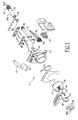
- FIG. 1 there is shown a control system 1 mechanical for air conditioning of a motor vehicle, this system being particular mounted on a dashboard (not shown) so at least part of its elements is accessible from the passenger compartment of the vehicle.
- This system generally includes a device for control 10 associated with a group 110 of control members.
- a device for control 10 associated with a group 110 of control members.
- the control device 10 is visible and directly accessible from the passenger compartment for handling by a passenger, while the control elements constitute the kinematics proper of the system 1 and are therefore located behind the dashboard which mask.
- the control device 10 comprises three means of ordered. It is constituted by an outer ring 20, rotating around a first axis X1, a central button 30 concentric with the ring 20 and rotating also around the axis X1, and a thumb wheel 40 mounted in a slot vertical of the central button 30 and rotating around a second axis X2 perpendicular to the first axis X1.
- the wheel 40 acts on the power of the air flow powered by a blower or a fan motor (not shown), the central button 30 acts on the temperature of the air flow and the outer ring 20 acts on the spatial distribution (feet, head / chest, demisting) of the air flow.
- these three means of control are independent of each other in their operation. So when manipulated in rotation, they each command their own control organ without acting on the other organs, even if two of the control means are mechanically linked as we will to see further. There is therefore no mechanical "interference" between the three control means, even if these are combined in one unit which one could call multifunction integrated actuator and which one sees better in Figures 2, 3 and 12.
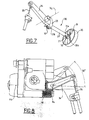
- FIG. 7 first shows the central button 30 and its control member 130.
- This first shaft 31 ends, at its opposite end 31b, with a bevel gear 32 engaged with a portion of gear wheel 33 conical of a first control lever 34 (see also Figure 1), said wheel 33 rotating around a fourth axis of rotation X4 perpendicular to the first axis.
- bevel gear 32 and the wheel portion conical 33 can be replaced by any other similar kinematics, such as than a straight pinion or cam system.
- the angular travel of the first lever is about 50 ° because the central button only turns on approximately 150 ° (substantially equal 3: 1 ratio between the bevel gear of the first shaft and the gear of the lever).
- Figure 9 shows the wheel 40 mounted in a vertical slot 30a of the central button 30, and its control member 140.
- This wheel 40 can rotate around the second axis of rotation X2 so as to act on the power of the air flow indicated by the figures (0 to 4) of figure 12.
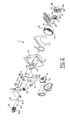
- This wheel 40 is slightly notched externally for easier "grip". It has an axis of rotation materialized by a tubular part 41 which is placed in two orifices of two ears 36/37 (see FIGS. 2 and 7) of the central button 30.
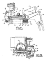
- This tubular part 41 also serves as a rotational connection between the first shaft 31 and the wheel 40, as can be clearly seen in FIGS. 13 and 14.
- the first shaft 31 has an axial notch defining two lugs 39 coming around the tubular part 41 to make the connection.
- the wheel 40 also has, internally, a portion 42 of a right gear which can rotate around the second axis of rotation X2 and which is engaged with a straight rack 43 extending along the first axis of rotation X1.
- This rack 43 is integral with a hollow rod 44 of axis X1 which has, at its end 44b opposite the rack 43, a succession of identical reductions and increases in diameter materialized for example by several regularly spaced 45 grooves axially. On these grooves 45, a side wheel 46 with straight teeth takes taken, this wheel 46 belonging to a lateral part 47 being for example connected to a system (not shown) for varying the power of the air flow.
- the right wheel portion 42 and the rack 43 can be replaced by a cam track (integral with the wheel) and a rod (integral with the hollow rod) perpendicular to the axis X1 as soon as the rotary movement of the dial 40 becomes a movement of translation of the hollow rod 44.
- the hollow rod 44 is mounted around the first shaft 31 and can thus slide axially along it (see Figures 13 and 14 by example). Furthermore, as the rotation of the central button 30 causes the rotation of the wheel 40 around the first axis X1 (the wheel being embedded in the slot 30a of the button), it is provided that the toothed wheel portion 42 of the wheel 40 always remains in engagement with the rack 43, on the one hand for avoid the teeth of the rack and the gear wheel portion being offset and no longer coincide, and on the other hand to be able to drive the rod digs in rotation when the central knob is turned.
- the wheel 40 is provided with two lateral stops 48 parallel to the first axis X1 (see FIG. 2 in particular) arranged on either side of the rack.
- the wheel 40 which causes the rack 43 (and therefore the hollow rod 44) to rotate around the axis X1 via the stops 48, but directly the first shaft 31.
- the first tree 31 has a section no longer circular but for example square, rectangular or other (in H), this section cooperating with an internal hollow shape of the hollow rod 44 to train the latter while allowing its translation around the first shaft 31 when the knob is simply turned.
- the first tree 31 has a housing 38 (FIG. 2) for the passage of the toothed wheel 41 of the thumb wheel 40.
- the wheel 40 is of course limited in rotation by stops (not shown) for example in the form of legs bearing against corresponding walls of the central button.
- An axial stop also exists between the hollow rod 44 and the bevel gear 32 of the first shaft 31 via a barrel 49 axial of the support 15 (see in particular Figures 13 and 14).
- FIG. 5 finally shows the ring 20 and its member command 120.
- This ring 20 can rotate around a first axis X1 of so as to act on the spatial position of the air flow indicated by the symbols visible in particular in Figure 12.
- This ring 20 can typically rotate about 220 ° to 260 ° around its axis X1 so as to cover all the proposed air flow direction positions (5 in this case: defog only, defog + feet, feet only, feet + thorax, and thorax alone).
- a wheel toothed 21 (invisible from the passenger compartment) with a right pinion which is engaged with a small straight pinion 23 complete located at the end 24a of a second shaft 24 (of preferably hollow to lighten the device) rotating around a fifth axis of rotation X5 parallel to the first axis X1.
- the shaft 24 is therefore offset by relative to the ring 20.
- the shaft 24 has a worm gear 25 which is engaged with a right gear portion 26 of a second control lever 27, this toothed wheel 26 rotating around a sixth axis of rotation X6 perpendicular to the first axis.
- the second tree 24 is mounted in a barrel 12 of a support piece 15 of plastic material ( Figure 6).
- Lever 27 can describe an arc of approximately 60 ° between its two extreme positions corresponding to the extreme positions of the ring 20.
- the majority of the rotational movements of different parts are limited by the configuration of the different gears. This is why, for example, the ring 20 has only a portion of toothed wheel 21 which does not make its entire circumference. For the same reasons, the gear 26 of the second lever 27 or the gear 42 of the wheel 40 are incomplete.
- This device is thus extremely compact and it respects everything meets the aesthetic and integration criteria specific to dashboards modern vehicles. It is also very easy to use and very reliable due to the use of kinematics using links pinion type mechanical, worm gear and rack.
- All parts are wear-resistant plastic, but it is possible to make some in other materials, for example in composites or metal such as aluminum or zamac.
Landscapes
- Physics & Mathematics (AREA)
- Engineering & Computer Science (AREA)
- Thermal Sciences (AREA)
- Mechanical Engineering (AREA)
- General Physics & Mathematics (AREA)
- Automation & Control Theory (AREA)
- Air-Flow Control Members (AREA)
- Mechanical Control Devices (AREA)
- Air-Conditioning For Vehicles (AREA)
Abstract
Description
- le premier moyen commande agit sur la localisation spatiale du flux d'air.
- le second moyen commande agit sur la température du flux d'air.
- le troisième moyen commande agit sur la puissance du flux d'air.
- les moyens de commande et les organes de commande sont réalisés en matière plastique.
- la figure 1 est une vue d'ensemble en perspective éclatée d'un système de commande pour un dispositif de ventilation ou de climatisation de véhicule automobile.
- la figure 2 est une vue similaire à la figure 1 mais prise sous un autre angle.
- la figure 3 est une vue similaire à la figure 1 mais avec les éléments montés,
- la figure 4 est une vue similaire à la figure 2 mais avec les éléments montés,
- la figure 5 est une vue de détail en perspective d'un moyen de commande,
- la figure 6 est une vue de côté gauche de la figure 5,
- la figure 7 est une vue de détail en perspective d'un autre moyen de commande,
- la figure 8 est une vue de côté droit de la figure 7,
- la figure 9 est une vue de détail en perspective d'un autre moyen de commande,
- la figure 10 est une vue de côté droit de la figure 9, avec un des moyens de commande en butée,
- la figure 11 est une vue de côté droit similaire à la figure 10 mais avec le moyen de commande en butée opposée,
- la figure 12 est une autre vue de face du système,
- la figure 13 est une vue en coupe (AA) de la figure 12, et
- la figure 14 est une autre vue ne coupe (BB) de la figure 12.
Claims (20)
- Dispositif (10) de commande mécanique permettant d'agir sur des organes de commande (130, 140) d'un système (1) de distribution d'un flux d'air pour véhicule automobile, caractérisé en ce qu'il comprend au moins deux moyens de commandes distincts (30, 40) à mouvement rotatif agissant respectivement de façon indépendante l'un par rapport à l'autre sur les organes de commande (130, 140), un premier moyen de commande étant monté tournant autour d'un premier axe de rotation et portant un second moyen de commande monté tournant autour d'un deuxième axe de rotation incliné par rapport au premier axe de rotation.
- Dispositif (10) selon la revendication 1, caractérisé en ce que le second moyen de commande (40) est articulé sur le premier moyen de commande (30) et tourne autour du second axe de rotation X2 qui est perpendiculaire au premier axe de rotation X1.
- Dispositif (10) selon l'une quelconque des revendications précédentes, caractérisé en ce que le premier moyen de commande est un bouton central (30) muni d'une fente (30a) et le second moyen de commande est (40) articulé dans ladite fente (30a).
- Dispositif (10) selon l'une quelconque des revendications précédentes, caractérisé en ce que le second moyen de commande (40) présente des moyens (42) pour transmettre, en tournant autour du second axe de rotation, X2, un mouvement de translation le long du premier axe X1 à une tige (44) qui présente des moyens (45) pour transformer ce mouvement de translation en un mouvement de rotation autour d'un troisième axe de rotation X3 perpendiculaire au premier axe, ce mouvement de rotation étant transmis à une pièce latérale de commande (47).
- Dispositif (10) selon la revendication 4, caractérisé en ce que le second moyen de commande est une molette (40) qui présente intérieurement une portion de roue dentée droite (42) tournant autour du second axe de rotation X2 pour agir sur une crémaillère (43) à denture droite s'étendant le long du premier axe X1 et solidaire de la tige (44), ladite tige étant par ailleurs munie, à l'extrémité (44b) opposée à la crémaillère (43), d'une succession de gorges (45) parallèles qui agissent axialement comme des dents en prise avec une roue dentée (46) de la pièce latérale de commande (47).
- Dispositif (10) selon l'une quelconque des revendications 3 à 5, caractérisé en ce que le bouton central rotatif (30) est lié à une extrémité (31a) d'un premier arbre (31) tournant autour du premier axe de rotation X1, cet arbre (31) présentant des moyens (32) pour transformer son mouvement de rotation en un autre mouvement de rotation autour d'un quatrième axe de rotation X4 perpendiculaire au premier axe X1 pour faire tourner un premier levier de commande (34).
- Dispositif (10) selon la revendication 6, caractérisé en ce que le premier arbre (31) du bouton de commande (30) est muni, à son extrémité opposée (31b), d'un engrenage conique (32) en prise avec une portion de roue dentée conique (33) du premier levier de commande (34).
- Dispositif (10) selon l'une quelconque des revendications 5 à 7, caractérisé en ce que la tige (44) est creuse et entoure le premier arbre (31) du bouton central (30) de façon à pouvoir coulisser axialement à l'extérieur de cet arbre le long du premier axe de rotation X1.
- Dispositif (10) selon l'une quelconque des revendications 3 à 8, caractérisé en ce que le bouton central (30) présente intérieurement deux oreilles (36, 37) espacées et parallèles au premier axe de rotation X1, ces oreilles (36, 37) étant traversées chacune d'un trou d'axe perpendiculaire au premier axe pour recevoir une partie tubulaire interne (41) de la molette (40) pour l'articulation de cette dernière autour du second axe de rotation X2.
- Dispositif (10) selon l'une quelconque des revendications 3 à 8, caractérisé en ce que le bouton central (30) présente intérieurement deux oreilles (36, 37) espacées et parallèles au premier axe de rotation X1, ces oreilles (36, 37) étant munies de protubérances d'axe X2 coopérant avec une partie tubulaire (41) de la molette (40) pour l'articulation de cette dernière autour du second axe de rotation X2.
- Dispositif (10) selon la revendication 9 ou 10, caractérisé en ce que le premier arbre (31) est muni axialement, à son extrémité (31a) de liaison au bouton central (30), d'une encoche (39) définissant une liaison avec la partie tubulaire (41) de la molette (40).
- Dispositif selon l'une quelconque des revendications 5 à 11, caractérisé en ce que la molette (40) présente également des moyens pour entraíner en rotation la tige (44) par l'intermédiaire de la crémaillère (43).
- Dispositif selon la revendication 12, caractérisé en ce que ces moyens sont constitués par deux parois (48) parallèles s'étendant le long du premier axe de rotation X1 et située dans l'environnement proche de la roue dentée pour entourer la crémaillère (43) de part et d'autre en faisant office de butée latérale d'entraínement.
- Dispositif (10) selon l'une quelconque des revendications précédentes, caractérisé en ce qu'il comprend en outre un troisième moyen de commande (20) disposé autour du premier moyen (30) et mobile en rotation autour du premier axe de rotation X1.
- Dispositif selon la revendication 14, caractérisé en ce que le troisième moyen de commande est constitué par une bague externe (20) tournant autour du premier axe de rotation X1 et munie de moyens (21) pour faire tourner un second arbre (24) autour d'un cinquième axe de rotation X5 parallèle au premier axe X1, cet arbre (24) présentant des moyens (25) pour transformer son mouvement de rotation en un autre mouvement de rotation autour d'un sixième axe de rotation X6 perpendiculaire au premier axe X1 pour faire tourner un second levier de commande (27).
- Dispositif selon la revendication 15, caractérisé en ce que la bague présente une portion de pignon droit (21) disposé sur sa périphérie externe et dont les dents sont en prise avec un engrenage droit (23) monté à une extrémité (24a) du second arbre (24), ledit arbre (24) présentant, à son autre extrémité (24b), une vis sans fin (25) agissant sur une portion de roue dentée (26) droite du second levier de commande (27).
- Dispositif (10) selon l'une quelconque des revendications précédentes, caractérisé en ce que le premier moyen de commande (20) agit sur la localisation spatiale du flux d'air.
- Dispositif (10) selon l'une quelconque des revendications précédentes, caractérisé en ce que le second moyen de commande (30) agit sur la température du flux d'air.
- Dispositif (10) selon l'une quelconque des revendications précédentes, caractérisé en ce que le troisième moyen de commande (40) agit sur la puissance du flux d'air.
- Dispositif (10) selon l'une quelconque des revendications précédentes, caractérisé en ce que les moyens de commande (20, 30, 40) et les organes de commande (120, 130, 140) sont réalisés en matière plastique.
Applications Claiming Priority (2)
| Application Number | Priority Date | Filing Date | Title |
|---|---|---|---|
| FR0013272A FR2815293B1 (fr) | 2000-10-17 | 2000-10-17 | Dispositif de commande pour systeme de distribution d'un flux d'air dans un vehicule |
| FR0013272 | 2000-10-17 |
Publications (2)
| Publication Number | Publication Date |
|---|---|
| EP1199197A1 true EP1199197A1 (fr) | 2002-04-24 |
| EP1199197B1 EP1199197B1 (fr) | 2009-11-04 |
Family
ID=8855425
Family Applications (1)
| Application Number | Title | Priority Date | Filing Date |
|---|---|---|---|
| EP01123971A Expired - Lifetime EP1199197B1 (fr) | 2000-10-17 | 2001-10-08 | Dispositif de commande pour système de distribution d'un flux d'air dans un véhicule |
Country Status (5)
| Country | Link |
|---|---|
| US (1) | US6405933B1 (fr) |
| EP (1) | EP1199197B1 (fr) |
| DE (1) | DE60140344D1 (fr) |
| ES (1) | ES2333404T3 (fr) |
| FR (1) | FR2815293B1 (fr) |
Families Citing this family (10)
| Publication number | Priority date | Publication date | Assignee | Title |
|---|---|---|---|---|
| FR2844481B1 (fr) * | 2002-09-13 | 2006-06-30 | Renault Sa | Dispositif de commande integre a une planche de bord de vehicule |
| JP4299089B2 (ja) | 2003-09-24 | 2009-07-22 | 株式会社東海理化電機製作所 | 車両用空調装置の操作装置 |
| FR2871103A1 (fr) * | 2004-06-04 | 2005-12-09 | Renault Sas | Commande de controle de l'ambiance thermique d'un habitacle de vehicule automobile |
| JP4884328B2 (ja) * | 2007-07-27 | 2012-02-29 | 株式会社ユーシン | 車両用空調コントロール操作装置 |
| US8018225B2 (en) * | 2008-11-25 | 2011-09-13 | General Electric Company | System and method for sensing the periodic position of an object |
| US8313675B2 (en) * | 2009-08-31 | 2012-11-20 | Coopervision International Holding Company, Lp | Demolding of ophthalmic lenses during the manufacture thereof |
| KR101534867B1 (ko) * | 2009-11-11 | 2015-07-07 | 기아자동차주식회사 | 자동차용 공기조화장치의 통합 제어 장치 |
| KR101417346B1 (ko) * | 2012-09-21 | 2014-07-08 | 기아자동차주식회사 | 차량의 공조시스템 조작장치 |
| WO2015153585A1 (fr) * | 2014-04-04 | 2015-10-08 | Kelsey-Hayes Company | Ensemble bouton rotatif à sortie d'angle de câble sélectionnable |
| KR101704916B1 (ko) * | 2015-08-18 | 2017-02-08 | 주식회사 니프코코리아 | 자동차용 에어벤트의 듀얼댐퍼장치 |
Citations (5)
| Publication number | Priority date | Publication date | Assignee | Title |
|---|---|---|---|---|
| FR1447250A (fr) | 1965-05-21 | 1966-07-29 | Renault | Dispositif de commande à manette unique pour la commande mécanique indépendante de trois organes commandés |
| DE19610148A1 (de) * | 1996-03-15 | 1997-09-18 | Bayerische Motoren Werke Ag | Wählorgan für eine Fahrzeug-Heiz- oder Klimaanlage |
| DE29715671U1 (de) * | 1997-09-01 | 1997-11-06 | Paul, Uwe, 97084 Würzburg | Anordnung der Heizungseinsteller in Kraftfahrzeugen |
| FR2782299A1 (fr) * | 1998-08-12 | 2000-02-18 | Valeo Electronique | Tableau de commande a double commande rotative pour vehicule automobile |
| US6115657A (en) * | 1997-03-03 | 2000-09-05 | Valeo Climatisation | Control device with a single manual control member for a motor vehicle installation, in particular a heating ventilating and/or air conditioning installation |
Family Cites Families (3)
| Publication number | Priority date | Publication date | Assignee | Title |
|---|---|---|---|---|
| US3971454A (en) * | 1971-04-20 | 1976-07-27 | Waterbury Nelson J | System for generating electrical energy to supply power to propel vehicles |
| DE3332984A1 (de) * | 1983-09-13 | 1985-03-28 | Aurora Konrad G. Schulz Gmbh & Co, 6933 Mudau | Anordnung von stellorganen, insbesondere fuer vorrichtungen zur beheizung und belueftung von fahrerkabinen, fahrgastraeumen od.dgl. in nutzfahrzeugen |
| EP0178455B1 (fr) * | 1984-09-26 | 1987-12-02 | Siemens Aktiengesellschaft | Dispositif de commande pour installation de chauffage, de climatisation et de ventilation pour véhicules automobiles |
-
2000
- 2000-10-17 FR FR0013272A patent/FR2815293B1/fr not_active Expired - Lifetime
-
2001
- 2001-10-04 US US09/969,661 patent/US6405933B1/en not_active Expired - Lifetime
- 2001-10-08 DE DE60140344T patent/DE60140344D1/de not_active Expired - Lifetime
- 2001-10-08 EP EP01123971A patent/EP1199197B1/fr not_active Expired - Lifetime
- 2001-10-08 ES ES01123971T patent/ES2333404T3/es not_active Expired - Lifetime
Patent Citations (5)
| Publication number | Priority date | Publication date | Assignee | Title |
|---|---|---|---|---|
| FR1447250A (fr) | 1965-05-21 | 1966-07-29 | Renault | Dispositif de commande à manette unique pour la commande mécanique indépendante de trois organes commandés |
| DE19610148A1 (de) * | 1996-03-15 | 1997-09-18 | Bayerische Motoren Werke Ag | Wählorgan für eine Fahrzeug-Heiz- oder Klimaanlage |
| US6115657A (en) * | 1997-03-03 | 2000-09-05 | Valeo Climatisation | Control device with a single manual control member for a motor vehicle installation, in particular a heating ventilating and/or air conditioning installation |
| DE29715671U1 (de) * | 1997-09-01 | 1997-11-06 | Paul, Uwe, 97084 Würzburg | Anordnung der Heizungseinsteller in Kraftfahrzeugen |
| FR2782299A1 (fr) * | 1998-08-12 | 2000-02-18 | Valeo Electronique | Tableau de commande a double commande rotative pour vehicule automobile |
Also Published As
| Publication number | Publication date |
|---|---|
| US6405933B1 (en) | 2002-06-18 |
| FR2815293A1 (fr) | 2002-04-19 |
| FR2815293B1 (fr) | 2003-04-18 |
| US20020045419A1 (en) | 2002-04-18 |
| DE60140344D1 (de) | 2009-12-17 |
| ES2333404T3 (es) | 2010-02-22 |
| EP1199197B1 (fr) | 2009-11-04 |
Similar Documents
| Publication | Publication Date | Title |
|---|---|---|
| FR2743764A1 (fr) | Mecanisme d'articulation pour siege de vehicule, et siege comportant un tel mecanisme | |
| EP1522448B1 (fr) | Dispositif de régulation d'un flux d'air entrant notamment sous le capot d'un véhicule automobile | |
| EP1021309B1 (fr) | Tableau de commande a double commande rotative pour vehicule automobile | |
| EP1199197B1 (fr) | Dispositif de commande pour système de distribution d'un flux d'air dans un véhicule | |
| EP0458702A1 (fr) | Actionneur, notamment pour la commande d'orientation d'un projecteur de véhicule automobile | |
| FR2863027A1 (fr) | Mecanisme demultiplicateur, en particulier pour un dispositif de reglage d'un siege de vehicule automobile. | |
| EP1911617B1 (fr) | Aérateur pour véhicule automobile | |
| EP1838541B1 (fr) | Buse d'aeration pour vehicule automobile destinee a etre placee en sortie d'un conduit d'aeration debouchant dans l'habitacle du vehicule, et vehicule correspondant | |
| EP1332900B1 (fr) | Aérateur, notamment pour véhicule automobile | |
| FR2809349A1 (fr) | Barillet d'aerateur pour vehicule automobile | |
| EP0908352B1 (fr) | Dispositif de réglage de l'orientation d'un faisceau lumineux d'un projecteur de véhicule automobile | |
| EP0588715A1 (fr) | Projecteur comportant un dispositif correcteur et des moyens de réglage du zéro du dispositif correcteur | |
| FR2713154A1 (fr) | Dispositif de distribution pour une installation de climatisation de véhicule automobile. | |
| EP1132228B1 (fr) | Installation de ventilation de l'habitacle d'un véhicule automobile | |
| FR2752775A1 (fr) | Dispositif de commande d'un volet pour une installation de chauffage et/ou climatisation de vehicule automobile | |
| FR2706818A1 (fr) | ||
| FR3095688A1 (fr) | Organe de commande pour bouche d’aeration compacte | |
| EP3299198B1 (fr) | Dispositif de volet d'obturation pour conduit d'aération | |
| EP1053118B1 (fr) | Dispositif de commande comportant des moyens de crantage | |
| EP0588725B1 (fr) | Projecteur comprenant un module correcteur à sortie rotative | |
| EP0064422A1 (fr) | Dispositif de commande à distance d'un miroir de rétroviseur pour véhicule | |
| EP0689959B1 (fr) | Mécanisme à vis sans fin, pour commander la position dans un projecteur d'automobile | |
| FR2764666A1 (fr) | Appareil de chauffage et/ou de climatisation comportant un dispositif de distribution d'air pour l'habitacle d'un vehicule | |
| FR2799695A1 (fr) | Dispositif de ventilation chauffage et/ou climatisation de l'habitacle d'un vehicule automobile, a commande integree | |
| EP0477047B1 (fr) | Dispositif de réglage de la température d'un système de climatisation, par exemple pour un véhicule automobile |
Legal Events
| Date | Code | Title | Description |
|---|---|---|---|
| PUAI | Public reference made under article 153(3) epc to a published international application that has entered the european phase |
Free format text: ORIGINAL CODE: 0009012 |
|
| AK | Designated contracting states |
Kind code of ref document: A1 Designated state(s): DE ES GB IT Kind code of ref document: A1 Designated state(s): AT BE CH CY DE DK ES FI FR GB GR IE IT LI LU MC NL PT SE TR |
|
| AX | Request for extension of the european patent |
Free format text: AL;LT;LV;MK;RO;SI |
|
| 17P | Request for examination filed |
Effective date: 20021002 |
|
| AKX | Designation fees paid |
Free format text: DE ES GB IT |
|
| 17Q | First examination report despatched |
Effective date: 20080430 |
|
| GRAP | Despatch of communication of intention to grant a patent |
Free format text: ORIGINAL CODE: EPIDOSNIGR1 |
|
| RIC1 | Information provided on ipc code assigned before grant |
Ipc: G05G 1/10 20060101ALI20090416BHEP Ipc: B60H 1/00 20060101AFI20090416BHEP |
|
| GRAS | Grant fee paid |
Free format text: ORIGINAL CODE: EPIDOSNIGR3 |
|
| GRAA | (expected) grant |
Free format text: ORIGINAL CODE: 0009210 |
|
| AK | Designated contracting states |
Kind code of ref document: B1 Designated state(s): DE ES GB IT |
|
| REG | Reference to a national code |
Ref country code: GB Ref legal event code: FG4D Free format text: NOT ENGLISH |
|
| REF | Corresponds to: |
Ref document number: 60140344 Country of ref document: DE Date of ref document: 20091217 Kind code of ref document: P |
|
| REG | Reference to a national code |
Ref country code: ES Ref legal event code: FG2A Ref document number: 2333404 Country of ref document: ES Kind code of ref document: T3 |
|
| PLBE | No opposition filed within time limit |
Free format text: ORIGINAL CODE: 0009261 |
|
| STAA | Information on the status of an ep patent application or granted ep patent |
Free format text: STATUS: NO OPPOSITION FILED WITHIN TIME LIMIT |
|
| 26N | No opposition filed |
Effective date: 20100805 |
|
| GBPC | Gb: european patent ceased through non-payment of renewal fee |
Effective date: 20101008 |
|
| PG25 | Lapsed in a contracting state [announced via postgrant information from national office to epo] |
Ref country code: GB Free format text: LAPSE BECAUSE OF NON-PAYMENT OF DUE FEES Effective date: 20101008 |
|
| PGFP | Annual fee paid to national office [announced via postgrant information from national office to epo] |
Ref country code: DE Payment date: 20201009 Year of fee payment: 20 Ref country code: IT Payment date: 20201008 Year of fee payment: 20 Ref country code: ES Payment date: 20201103 Year of fee payment: 20 |
|
| REG | Reference to a national code |
Ref country code: DE Ref legal event code: R071 Ref document number: 60140344 Country of ref document: DE |
|
| REG | Reference to a national code |
Ref country code: ES Ref legal event code: FD2A Effective date: 20220126 |
|
| PG25 | Lapsed in a contracting state [announced via postgrant information from national office to epo] |
Ref country code: ES Free format text: LAPSE BECAUSE OF EXPIRATION OF PROTECTION Effective date: 20211009 |