EP1199133A1 - Wiper for machine tool - Google Patents
Wiper for machine tool Download PDFInfo
- Publication number
- EP1199133A1 EP1199133A1 EP00913107A EP00913107A EP1199133A1 EP 1199133 A1 EP1199133 A1 EP 1199133A1 EP 00913107 A EP00913107 A EP 00913107A EP 00913107 A EP00913107 A EP 00913107A EP 1199133 A1 EP1199133 A1 EP 1199133A1
- Authority
- EP
- European Patent Office
- Prior art keywords
- wiper
- sliding
- fabric
- fabric material
- lip portion
- Prior art date
- Legal status (The legal status is an assumption and is not a legal conclusion. Google has not performed a legal analysis and makes no representation as to the accuracy of the status listed.)
- Granted
Links
Images



Classifications
-
- B—PERFORMING OPERATIONS; TRANSPORTING
- B23—MACHINE TOOLS; METAL-WORKING NOT OTHERWISE PROVIDED FOR
- B23Q—DETAILS, COMPONENTS, OR ACCESSORIES FOR MACHINE TOOLS, e.g. ARRANGEMENTS FOR COPYING OR CONTROLLING; MACHINE TOOLS IN GENERAL CHARACTERISED BY THE CONSTRUCTION OF PARTICULAR DETAILS OR COMPONENTS; COMBINATIONS OR ASSOCIATIONS OF METAL-WORKING MACHINES, NOT DIRECTED TO A PARTICULAR RESULT
- B23Q11/00—Accessories fitted to machine tools for keeping tools or parts of the machine in good working condition or for cooling work; Safety devices specially combined with or arranged in, or specially adapted for use in connection with, machine tools
- B23Q11/08—Protective coverings for parts of machine tools; Splash guards
-
- B—PERFORMING OPERATIONS; TRANSPORTING
- B23—MACHINE TOOLS; METAL-WORKING NOT OTHERWISE PROVIDED FOR
- B23Q—DETAILS, COMPONENTS, OR ACCESSORIES FOR MACHINE TOOLS, e.g. ARRANGEMENTS FOR COPYING OR CONTROLLING; MACHINE TOOLS IN GENERAL CHARACTERISED BY THE CONSTRUCTION OF PARTICULAR DETAILS OR COMPONENTS; COMBINATIONS OR ASSOCIATIONS OF METAL-WORKING MACHINES, NOT DIRECTED TO A PARTICULAR RESULT
- B23Q11/00—Accessories fitted to machine tools for keeping tools or parts of the machine in good working condition or for cooling work; Safety devices specially combined with or arranged in, or specially adapted for use in connection with, machine tools
- B23Q11/08—Protective coverings for parts of machine tools; Splash guards
- B23Q11/0875—Wipers for clearing foreign matter from slideways or slidable coverings
Definitions
- the present invention relates to a wiper for machine tools which is operated on sliding surfaces of machine tools and industrial machines to scrape chips, cutting lubricants, and the like which are present on the sliding surfaces, for the purpose of preventing these chips and cutting lubricants from entering the sliding surfaces.
- a wiper used to remove chips and cutting lubricants from a machine tool includes a lip portion having a sliding portion which is typically made of a rubber material.
- the reason a rubber material is adopted is that the elasticity thereof is utilized to improve the conforming and scraping capabilities of the wiper in all directions.
- a wiper including a sliding portion made of thin spring steel has been proposed.
- the wiper is often deformed due to its thinness, causing inconvenience of handling.
- scattered chips strike and bend the spring steel, resulting in a reduction in the closeness of the wiper.
- spring steel is a metallic material, sliding surfaces may be damaged, or the spring steel may be corroded.
- a wiper for machine tools includes an attachment portion to be attached to a machine tool, wherein the machine tool is moved relative to a sliding surface, and a wiper body made of an elastic material integrated with the attachment portion.
- a lip portion of the wiper body can be slid on the sliding surface, and a fabric material is provided on at least a sliding surface side of the lip portion of the wiper body.
- the fabric material is made of at least one material selected from the group consisting of aromatic polyamide, aliphatic polyamide, and polyester.
- the lip portion of the wiper body is covered with the fabric material.
- the fabric material is made of weave fabric or knit fabric, and a thickness of the fabric material is 0.5 mm or more.
- a fineness of a thread included in the fabric material is 100 deniers or more.
- a coefficient of friction of a thread included in the fabric material is in the range of 0.1 to 0.3.
- a fabric material is provided on at least a sliding side of a lip portion of a wiper, the coefficient of friction of the lip portion with a sliding surface is reduced and abrasion loss is reduced. Therefore, closeness can be maintained for a long time. Further, the low coefficient of friction allows the wiper to be slid at a high rate. Further, since a sliding portion of the lip portion includes a fabric material, a sliding surface does not suffer from scratches which would be otherwise observed when the sliding portion is made of a metallic material. A defective product due to warpage of a wiper caused by collision or impact with chips, or the like, can be avoided.
- the thickness of a fabric material (original fabric) is set to be 0.5 mm or more (particularly 1 mm or more), or the fineness of a thread included in the fabric material is set to be 100 deniers or more (particularly, the fineness of wefts extending in a direction perpendicular to a sliding direction is set to 400 deniers or more). Therefore, the life of the wiper can be lengthened in fast sliding operations.
- a lip portion of a wiper body is covered with a fabric material, whereby the friction resistance of the lip portion is small and therefore a fast sliding operation can be performed and the amount of leaked chips is small over long-term use.
- a sliding portion of the lip portion includes a fabric material, a sliding surface does not suffer from scratches which would be otherwise observed when the sliding portion is made of a metallic material. A defective product due to warpage of a wiper caused by collision or impact with chips, or the like, can be avoided.
- the wiper of the present invention can be used for machine tools which are moved at a high speed. Further, since scraping can be satisfactorily performed in an operation without cutting oil, the wiper of the present invention is applicable to particular operations, such as aluminum cutting.
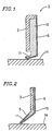
- a wiper 1 for machine tools includes an attachment portion 3 attached to a machine tool which is reciprocated with respect to a sliding surface 14 (e.g., a machine surface or a cover surface), and a wiper body 10 which is made of an elastic material and is integrated with the attachment portion 3.
- a sliding surface 14 e.g., a machine surface or a cover surface
- a wiper body 10 which is made of an elastic material and is integrated with the attachment portion 3.
- the attachment portion 3 is also called a cored bar and is typically made of a metallic material.
- the wiper body 10 is formed as a long member which transversely extends.
- a lip portion 11 is provided at a lower portion of the wiper body 10, a thickness of which is gradually decreased toward a tip side thereof.
- the wiper body 10 is made of an elastic material, such as NBR, urethane rubber, fluorocarbon rubber, or H-NBR, is oil-resistant, and has a suitable elasticity in the hardness range of 70 to 90 (typically 70).
- At least the lip portion 11 is covered with a fabric material 5.
- the fabric material 5 may be made of one or more synthetic fibers (e.g., aliphatic polyamide, aromatic polyamide, and polyester), natural fiber, glass fiber, and metal fiber having a relatively low stiffness, and preferably made of a synthetic fiber, such as aliphatic polyamide, aromatic polyamide, or polyester.
- the fabric material 5 may be in the form of weave fabric, knit fabric, or the like, and is preferably in the form of weave fabric.
- the thickness of the fabric material is preferably in the range of 0.25 mm to 2.0 mm, more preferably 0.5 mm to 1.5 mm, and even more preferably 0.5 mm to 1.0 mm.
- the fineness of the fibers of the fabric material is preferably in the range of 50 deniers to 500 deniers, and more preferably 100 deniers to 450 deniers.
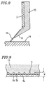
- the fabric material 5 is provided at a sliding surface side of the lip portion 11 in such a manner that wefts 5a of the weave or knit fabric are orthogonal to a sliding direction of the lip portion 11.
- the fineness of the wefts 5a is preferably in the range of 80 deniers to 500 deniers, and more preferably 100 deniers to 450 deniers.
- the fineness of the warps 5b may be about half the fineness of the wefts 5a, for example, 40 deniers to 250 deniers, and more preferably 50 deniers to 200 deniers.
- the life of the wiper 1 can be lengthened in high-speed operation. If the stiffness of a waist portion of the lip portion 11 is excessively increased, the stiffness of the wiper itself is increased and therefore the pressing force of the lip portion 11 is increased. This problem can be solved by the fineness of the warps 5b being smaller than that of the wefts 5a. Taking into consideration the linear shape of the edge of the lip portion 11, the area where the fabric material 5 makes contact with the sliding surface is increased, so that the life of the wiper is expected to be lengthened.
- the fabric material 5 may be subjected to adhesion treatment or rubber impregnation treatment.
- the fabric material 5 may be adhered to a lower surface of the lip portion 11 of the wiper body 10 using an adhesive or by vulcanization.
- the fabric material 5 may cover the wiper body 10, specifically, the lip portion 11 and a side surface of the wiper body 10. As shown in Figures 2 and 3, upper and lower surfaces of the lip portion 11 of the wiper body 10 and the side surface of the wiper body 10 may be covered with the fabric material 5.
- the fabric material 5 may be provided on the lower surface (sliding surface) of the lip portion 11.
- the coefficient of friction of the lip portion 11 with respect to the sliding surface 14 is smaller than that of a conventional lip portion of rubber without a fabric material cover. Therefore, abrasion loss can be reduced, whereby closeness can be maintained for a long time.
- a conventional wiper including a sliding portion made of a metallic material has a low level of sliding resistance, the amount of chips leaked during an actual sliding operation is larger in the conventional wiper than in the wiper of the present invention.
- a wiper has a higher level of closeness when a sliding portion is made of elastic rubber.
- the sliding resistance is smaller than that of conventional sliding portions than when the sliding portion is made of a metallic material having a higher level of rigidity.
- Synthetic fibers used in weave fabric or the like have a small coefficient of friction (typically, 0.1 to 0.3). Synthetic fibers are also deformable and therefore do not hinder elastic deformation of the rubber. Therefore, the wiper 1 covered with the fabric material 5 made of synthetic fiber can be slid without losing closeness.
- the outer surface of the lip portion 11 of the wiper body 10 is provided with the fabric material 5, so that the fabric material 5 makes contact with the sliding surface 14. Therefore, the frictional resistance of the wiper sliding portion is decreased, whereby abrasion can be reduced and the sliding surface 14 is prevented from being damaged.
- the fabric material 5 (e.g., weave fabric made of a synthetic resin fiber) is provided on a predetermined portion of a mold.
- the mold is filled with unvulcanized rubber.
- the unvulcanized rubber is then vulcanized.
- the wiper body 10 is thus produced and at the same time the fabric material 5 is vulcanized to be adhered to the wiper body 10.
- a portion of the unvulcanized rubber is vulcanized while permeating the fabric material 5 or passing through stitches of the fabric material 5, whereby the wiper body 10 and the fabric material 5 are integrated together and therefore the adhesive strength therebetween is enhanced.
- the present invention is applicable to wipers having various sizes and shapes for the purposes of removing chips and coolant produced during operations of machine tools and industrial machines.
- a cored bar was placed in a mold.
- the mold was filled with unvulcanized NBR followed by vulcanization.
- a wiper including a cored bar 3 and a wiper body 10 as shown in Figure 7 was obtained.
- a wiper body 10 was made of NBR.
- a thin metal plate 12 was adhered to a lower surface of a lip portion 11 of the wiper body 10 by vulcanization, thereby obtaining a wiper 1 as shown in Figure 8.
- the wiper 1 was used, and the pressing force, sliding resistance and the amount of leaked chips were measured. The results are shown in Table 1 .
- a cored bar and a weave fabric made of synthetic fibers were placed in a mold.
- the mold was filled with unvulcanized NBR followed by vulcanization.
- the wiper 1 including the cored bar 3 and the wiper body 10 as shown in Figure 1 was obtained.
- a lip portion 11 of the wiper body 10 was covered with the weave fabric 5 .
- the wiper 1 was used, and the pressing force, sliding resistance and the amount of leaked chips were measured. The results are shown in Table 1 .
- Comparative Example 1 the lip portion of the wiper made only of rubber had a high level of sliding resistance. The closeness of the wiper was lowered after long-term use, causing a large amount of leaked chips.
- Comparative Example 2 the wiper including a sliding portion made of a metallic material had a low level of sliding resistance. The amount of leaked chips was small, but was larger than that of Example 1. Accordingly, when the sliding portion was made of elastic rubber, which has a sliding resistance smaller than that of Comparative Example 1 (conventional wiper), instead of a metallic material having a high level of rigidity, a higher level of closeness could be obtained.
- Example 1 rigid fibers, such as weave fabric, have small coefficients of friction. Rigid fibers are also deformable and therefore do not hinder elastic deformation of the rubber. Therefore, a wiper can be slid without losing closeness.
- a sliding portion which is slid on a sliding surface is made of a metallic material, since a metallic material has a smaller level of abrasion loss than that of rubber, the abrasion life is excellent.
- a rubber having a high level of elasticity allows for a higher level of closeness than that of a metallic material having a high level of rigidity.
- a cored bar and a weave fabric made of synthetic fibers (nylon 6,6) were placed in a mold.
- the mold was filled with unvulcanized NBR followed by vulcanization.
- the wiper 1 including the cored bar 3 and the wiper body 10 as shown in Figure 10 was obtained.
- a sliding surface of a lip portion 11 of the wiper body 10 was covered with the weave fabric 5.
- the weave fabric used had a thickness of 0.5 mm (measured for the original fabric).
- the fineness of the wefts of the weave fabric was 100 deniers, while the fineness of the warps of the weave fabric was 50 deniers.
- the weave fabric was provided on a lower surface of the lip portion in such a manner that the wefts were provided orthogonal to a sliding direction.
- This wiper was used, and the abrasion resistance thereof was measured under the following conditions.
- the distance traveled by the wiper 1 until abnormal noise occurred was 650 Km.
- a fabric material (original fabric to be used for a fabric layer) had a thickness of 1.0 mm, and the fineness of the wefts of the fabric material was 420 deniers, while the fineness of the warps of the fabric material was 210 deniers.
- a wiper of Example 3 was the same as that of Example 2. The abrasion resistance of the wiper of Example 3 was measured.
- the distance traveled by the wiper until abnormal noise occurred was 2000 km.
- the distance traveled by the wiper until abnormal noise occurred was 30 km.
- a wiper for machine tools is provided in which a lip portion has a low level of abrasion resistance, and a low level of abrasion loss is small.
- a wiper for machine tools is provided in which no damages are caused due to collision or impact with chips and a sliding surface does not suffer from damages or the like.
Landscapes
- Engineering & Computer Science (AREA)
- Mechanical Engineering (AREA)
- Woven Fabrics (AREA)
- Cleaning In General (AREA)
- Screen Printers (AREA)
- Lubricants (AREA)
- Brushes (AREA)
Abstract
Description

Claims (6)
- (Amended) A wiper for machine tools comprising: an attachment portion to be attached to a machine tool, wherein the machine tool is moved relative to a sliding surface; and a wiper body made of an elastic material integrated with the attachment portion, wherein a lip portion of the wiper body can be slid on the sliding surface, the lip portion of the wiper body is covered with a fabric material and the fabric material is provided on at least a sliding surface side of the lip portion of the wiper body.
- A wiper for machine tools according to claim 1, wherein the fabric material is made of at least one material selected from the group consisting of aromatic polyamide, aliphatic polyamide, and polyester.
- (Amended) A wiper for machine tools according to claim 1, wherein the fabric material is made of weave fabric or knit fabric, and a thickness of the fabric material is 0.25 mm or more.
- (Amended) A wiper for machine tools according to claim 1, wherein a fineness of a thread included in the fabric material is 50 deniers or more.
- (Amended) A wiper for machine tools according to claim 1, wherein a coefficient of friction of a thread included in the fabric material is in the range of 0.1 to 0.3.
- (New) A wiper for machine tools comprising: an attachment portion to be attached to a machine tool, wherein the machine tool is moved relative to a sliding surface; and a wiper body made of an elastic material integrated with the attachment portion, wherein a lip portion of the wiper body can be slid on the sliding surface, a fabric material is provided on at least a sliding surface side of the lip portion of the wiper body, and the fabric material is made of weave fabric or knit fabric and has a thickness of 0.25 mm or more.
Applications Claiming Priority (5)
| Application Number | Priority Date | Filing Date | Title |
|---|---|---|---|
| JP10067699 | 1999-04-07 | ||
| JP10067699 | 1999-04-07 | ||
| JP29030299 | 1999-10-12 | ||
| JP29030299A JP3193361B2 (en) | 1999-04-07 | 1999-10-12 | Wipers for machine tools |
| PCT/JP2000/002185 WO2000061332A1 (en) | 1999-04-07 | 2000-04-04 | Wiper for machine tool |
Publications (3)
| Publication Number | Publication Date |
|---|---|
| EP1199133A1 true EP1199133A1 (en) | 2002-04-24 |
| EP1199133A4 EP1199133A4 (en) | 2004-04-14 |
| EP1199133B1 EP1199133B1 (en) | 2005-08-17 |
Family
ID=26441655
Family Applications (1)
| Application Number | Title | Priority Date | Filing Date |
|---|---|---|---|
| EP00913107A Expired - Lifetime EP1199133B1 (en) | 1999-04-07 | 2000-04-04 | Wiper for machine tool |
Country Status (12)
| Country | Link |
|---|---|
| US (1) | US6623011B1 (en) |
| EP (1) | EP1199133B1 (en) |
| JP (1) | JP3193361B2 (en) |
| KR (1) | KR100413925B1 (en) |
| CN (1) | CN1120765C (en) |
| AU (1) | AU750580B2 (en) |
| CA (1) | CA2369102C (en) |
| DE (1) | DE60022055T2 (en) |
| ES (1) | ES2246837T3 (en) |
| HK (1) | HK1043338B (en) |
| TW (1) | TW476688B (en) |
| WO (1) | WO2000061332A1 (en) |
Cited By (1)
| Publication number | Priority date | Publication date | Assignee | Title |
|---|---|---|---|---|
| CN105960309A (en) * | 2014-02-06 | 2016-09-21 | 阪东化学株式会社 | Sealing member for machine tools |
Families Citing this family (17)
| Publication number | Priority date | Publication date | Assignee | Title |
|---|---|---|---|---|
| JP4745636B2 (en) * | 2004-09-29 | 2011-08-10 | ニッタ株式会社 | Wiper |
| JP2007083344A (en) * | 2005-09-22 | 2007-04-05 | Nitta Ind Corp | Industrial wipers |
| JP5043481B2 (en) * | 2007-03-15 | 2012-10-10 | オークマ株式会社 | Wiper |
| JP5531270B2 (en) * | 2007-03-28 | 2014-06-25 | 三ツ星ベルト株式会社 | Wiper |
| JP2011225224A (en) * | 2010-04-16 | 2011-11-10 | Nitta Corp | Scraper for dispensing/packaging apparatus |
| JP5661829B2 (en) | 2013-02-21 | 2015-01-28 | ファナック株式会社 | Machine tool with chip scraping member |
| WO2015099087A1 (en) | 2013-12-26 | 2015-07-02 | ニッタ株式会社 | Wiper and method for manufacturing same |
| US10215286B2 (en) | 2014-09-11 | 2019-02-26 | Aktiebolaget Skf | Dynamic seal |
| JP6088084B2 (en) * | 2016-03-18 | 2017-03-01 | 三ツ星ベルト株式会社 | Manufacturing method of wiper |
| JP6525933B2 (en) | 2016-10-11 | 2019-06-05 | ファナック株式会社 | Machine Tools |
| JP7000086B2 (en) * | 2017-09-12 | 2022-01-19 | ニッタ株式会社 | How to manufacture wipers for machine tools and wipers for machine tools |
| JP2022089690A (en) * | 2020-12-04 | 2022-06-16 | ニッタ株式会社 | Wiper |
| USD1001853S1 (en) * | 2021-02-04 | 2023-10-17 | Keyarrow (Taiwan) Co., Ltd. | Wiper blade holder for a protective cover of a machine tool |
| CN115013533A (en) * | 2021-03-03 | 2022-09-06 | 艾志(南京)环保管接技术股份有限公司 | Split oil seal composed of double springs and double rings |
| JP7779532B2 (en) * | 2022-04-05 | 2025-12-03 | 三和テクノ株式会社 | Sealants and methods for installing sealants |
| JP2024108016A (en) * | 2023-01-30 | 2024-08-09 | ニッタ株式会社 | Wipers |
| CN116673241A (en) * | 2023-07-15 | 2023-09-01 | 佛山墨家科技有限公司 | Cleaning mechanism for light curtain transparent sheet in size measuring device |
Family Cites Families (18)
| Publication number | Priority date | Publication date | Assignee | Title |
|---|---|---|---|---|
| US3901517A (en) * | 1972-10-11 | 1975-08-26 | Utex Ind Inc | Dynamic seal |
| FR2255816A5 (en) * | 1973-12-19 | 1975-07-18 | Dechavanne Jacques | |
| US4327924A (en) * | 1979-09-06 | 1982-05-04 | The Texacone Company | Seal for elevator drive mechanism |
| DE3442082A1 (en) * | 1984-11-17 | 1986-05-28 | Wilhelm Carl GmbH & Co, Metalltechnik, 7333 Ebersbach | Wiping device on telescopically nesting boxes of protective covers |
| DE3545168A1 (en) * | 1985-12-20 | 1987-06-25 | Wilhelm Carl Gmbh & Co Metallt | Wiping device on telescoping boxes of protective covers |
| DE8613005U1 (en) * | 1986-05-13 | 1986-09-11 | Gebr. Hennig Gmbh, 8045 Ismaning | Stripping device for telescopic steel covers |
| DE3863833D1 (en) * | 1987-05-13 | 1991-08-29 | Gebr Hennig Gmbh | SCRAPER. |
| JPH0274146A (en) * | 1988-09-06 | 1990-03-14 | Toshiba Corp | Attenuator of turning effort of rotor |
| JPH0274146U (en) | 1988-11-24 | 1990-06-06 | ||
| DE9102555U1 (en) * | 1991-03-04 | 1991-05-23 | Gebr. Hennig Gmbh, 8045 Ismaning | Scraper device for a telescopic cover |
| JP2947376B2 (en) * | 1991-08-13 | 1999-09-13 | バンドー化学株式会社 | Machine tool chip removal scraper |
| DE4336692A1 (en) * | 1993-10-27 | 1995-05-04 | Fischer & Partner Wilf | Guideway scraper |
| US5509669A (en) * | 1995-06-19 | 1996-04-23 | General Electric Company | Gas-path leakage seal for a gas turbine |
| DE19730120A1 (en) * | 1997-07-14 | 1999-01-21 | Gebr Hennig Gmbh | Scraper |
| US6047970A (en) * | 1997-12-22 | 2000-04-11 | Caterpillar Inc. | Rod scraper |
| JP2000042863A (en) * | 1998-07-29 | 2000-02-15 | Nitta Ind Corp | Industrial scraper |
| JP2001310238A (en) * | 2000-04-28 | 2001-11-06 | Nok Corp | Scraper for machine tool |
| JP2002046040A (en) * | 2000-08-04 | 2002-02-12 | Nok Corp | Scraper for machine tool |
-
1999
- 1999-10-12 JP JP29030299A patent/JP3193361B2/en not_active Expired - Lifetime
-
2000
- 2000-04-04 WO PCT/JP2000/002185 patent/WO2000061332A1/en not_active Ceased
- 2000-04-04 ES ES00913107T patent/ES2246837T3/en not_active Expired - Lifetime
- 2000-04-04 US US09/958,386 patent/US6623011B1/en not_active Expired - Lifetime
- 2000-04-04 CN CN00806941A patent/CN1120765C/en not_active Expired - Lifetime
- 2000-04-04 CA CA002369102A patent/CA2369102C/en not_active Expired - Fee Related
- 2000-04-04 EP EP00913107A patent/EP1199133B1/en not_active Expired - Lifetime
- 2000-04-04 AU AU34600/00A patent/AU750580B2/en not_active Expired
- 2000-04-04 DE DE60022055T patent/DE60022055T2/en not_active Expired - Lifetime
- 2000-04-04 KR KR10-2001-7012746A patent/KR100413925B1/en not_active Expired - Lifetime
- 2000-04-04 HK HK02104665.4A patent/HK1043338B/en not_active IP Right Cessation
- 2000-04-06 TW TW089106305A patent/TW476688B/en not_active IP Right Cessation
Cited By (4)
| Publication number | Priority date | Publication date | Assignee | Title |
|---|---|---|---|---|
| CN105960309A (en) * | 2014-02-06 | 2016-09-21 | 阪东化学株式会社 | Sealing member for machine tools |
| EP3103584A4 (en) * | 2014-02-06 | 2017-11-29 | Bando Chemical Industries, Ltd. | Sealing member for machine tools |
| CN105960309B (en) * | 2014-02-06 | 2018-12-14 | 阪东化学株式会社 | Work mechanism containment member |
| US10335910B2 (en) | 2014-02-06 | 2019-07-02 | Bando Chemical Industries, Ltd. | Sealing member for machine tools |
Also Published As
| Publication number | Publication date |
|---|---|
| TW476688B (en) | 2002-02-21 |
| KR100413925B1 (en) | 2004-01-07 |
| HK1043338A1 (en) | 2002-09-13 |
| KR20020005660A (en) | 2002-01-17 |
| WO2000061332A1 (en) | 2000-10-19 |
| EP1199133B1 (en) | 2005-08-17 |
| DE60022055D1 (en) | 2005-09-22 |
| AU3460000A (en) | 2000-11-14 |
| HK1043338B (en) | 2005-12-09 |
| CA2369102A1 (en) | 2000-10-19 |
| EP1199133A4 (en) | 2004-04-14 |
| JP3193361B2 (en) | 2001-07-30 |
| ES2246837T3 (en) | 2006-03-01 |
| CN1349444A (en) | 2002-05-15 |
| AU750580B2 (en) | 2002-07-25 |
| US6623011B1 (en) | 2003-09-23 |
| CN1120765C (en) | 2003-09-10 |
| JP2000354934A (en) | 2000-12-26 |
| DE60022055T2 (en) | 2006-06-01 |
| CA2369102C (en) | 2005-10-04 |
Similar Documents
| Publication | Publication Date | Title |
|---|---|---|
| CA2369102C (en) | Wiper for machine tool | |
| US8905099B2 (en) | Low noise pneumatic tire | |
| KR102341012B1 (en) | Wiper and method for manufacturing same | |
| CA2559040C (en) | Paper making elastic belt | |
| CN1904196B (en) | Die and method of manufacturing a retaining seal using the die | |
| JP3160541U (en) | Machine tool wiper | |
| JP2020032336A (en) | Wiper | |
| JP3466106B2 (en) | Machine tool wipers | |
| JP2007083344A (en) | Industrial wipers | |
| JP4343791B2 (en) | Vulcanized rubber wear test method | |
| Sengupta et al. | On the mechanism behind the punch-blank surface conformation in stretch-forming and deep-drawing | |
| JP2003053641A (en) | Wiper members for machine tools | |
| JP2009202074A (en) | Wiper | |
| JP6454198B2 (en) | Wiper | |
| AU2005226311B2 (en) | Press roll for paper machine, method of manufacturing the same, pressing method for wet paper, and surface polishing method for paper machine press roll | |
| JP3863556B1 (en) | Machine tool wiper | |
| Iwai et al. | Transition of the lubricated wear of carbon steel | |
| EP0054368B1 (en) | Improvements in or relating to a smoothing pad | |
| CN213647701U (en) | Roller rubber surface grain removing tool and roller rubber surface grain removing device | |
| Henning et al. | Analysis of Contact Wheel and Tool Interaction in Belt Grinding | |
| SASADA | Tsudanuma, Narashino-shi, Chiba 275-8588 Nippon | |
| BABA et al. | Two critical events observed on Cu films on glass | |
| Chattopadhyay | Wear prognosis methodology | |
| Stout et al. | Fly Cut Surfaces | |
| Szuder et al. | A Theoretical and Experimental Study of the Influences on Flat Lapping |
Legal Events
| Date | Code | Title | Description |
|---|---|---|---|
| PUAI | Public reference made under article 153(3) epc to a published international application that has entered the european phase |
Free format text: ORIGINAL CODE: 0009012 |
|
| 17P | Request for examination filed |
Effective date: 20011029 |
|
| AK | Designated contracting states |
Kind code of ref document: A1 Designated state(s): AT BE CH CY DE DK ES FI FR GB GR IE IT LI LU MC NL PT SE |
|
| A4 | Supplementary search report drawn up and despatched |
Effective date: 20040227 |
|
| RBV | Designated contracting states (corrected) |
Designated state(s): CH DE ES FR GB LI |
|
| 17Q | First examination report despatched |
Effective date: 20040806 |
|
| GRAP | Despatch of communication of intention to grant a patent |
Free format text: ORIGINAL CODE: EPIDOSNIGR1 |
|
| RBV | Designated contracting states (corrected) |
Designated state(s): CH DE ES FR GB LI |
|
| RBV | Designated contracting states (corrected) |
Designated state(s): CH DE ES FR GB IT LI |
|
| GRAS | Grant fee paid |
Free format text: ORIGINAL CODE: EPIDOSNIGR3 |
|
| GRAA | (expected) grant |
Free format text: ORIGINAL CODE: 0009210 |
|
| AK | Designated contracting states |
Kind code of ref document: B1 Designated state(s): CH DE ES FR GB IT LI |
|
| REG | Reference to a national code |
Ref country code: GB Ref legal event code: FG4D |
|
| REG | Reference to a national code |
Ref country code: CH Ref legal event code: EP |
|
| REF | Corresponds to: |
Ref document number: 60022055 Country of ref document: DE Date of ref document: 20050922 Kind code of ref document: P |
|
| REG | Reference to a national code |
Ref country code: HK Ref legal event code: GR Ref document number: 1043338 Country of ref document: HK |
|
| REG | Reference to a national code |
Ref country code: CH Ref legal event code: NV Representative=s name: NOVAGRAAF INTERNATIONAL SA |
|
| REG | Reference to a national code |
Ref country code: ES Ref legal event code: FG2A Ref document number: 2246837 Country of ref document: ES Kind code of ref document: T3 |
|
| ET | Fr: translation filed | ||
| PLBE | No opposition filed within time limit |
Free format text: ORIGINAL CODE: 0009261 |
|
| STAA | Information on the status of an ep patent application or granted ep patent |
Free format text: STATUS: NO OPPOSITION FILED WITHIN TIME LIMIT |
|
| 26N | No opposition filed |
Effective date: 20060518 |
|
| REG | Reference to a national code |
Ref country code: CH Ref legal event code: PFA Owner name: NITTA CORPORATION Free format text: NITTA CORPORATION#4-26, SAKURAGAWA 4-CHOME, NANIWA-KU#OSAKA-SHI, OSAKA 556-0022 (JP) -TRANSFER TO- NITTA CORPORATION#4-26, SAKURAGAWA 4-CHOME, NANIWA-KU#OSAKA-SHI, OSAKA 556-0022 (JP) |
|
| REG | Reference to a national code |
Ref country code: FR Ref legal event code: PLFP Year of fee payment: 17 |
|
| PGFP | Annual fee paid to national office [announced via postgrant information from national office to epo] |
Ref country code: ES Payment date: 20160413 Year of fee payment: 17 Ref country code: GB Payment date: 20160421 Year of fee payment: 17 Ref country code: CH Payment date: 20160420 Year of fee payment: 17 Ref country code: DE Payment date: 20160421 Year of fee payment: 17 |
|
| PGFP | Annual fee paid to national office [announced via postgrant information from national office to epo] |
Ref country code: IT Payment date: 20160427 Year of fee payment: 17 Ref country code: FR Payment date: 20160421 Year of fee payment: 17 |
|
| REG | Reference to a national code |
Ref country code: DE Ref legal event code: R119 Ref document number: 60022055 Country of ref document: DE |
|
| REG | Reference to a national code |
Ref country code: CH Ref legal event code: PL |
|
| GBPC | Gb: european patent ceased through non-payment of renewal fee |
Effective date: 20170404 |
|
| REG | Reference to a national code |
Ref country code: FR Ref legal event code: ST Effective date: 20171229 |
|
| PG25 | Lapsed in a contracting state [announced via postgrant information from national office to epo] |
Ref country code: FR Free format text: LAPSE BECAUSE OF NON-PAYMENT OF DUE FEES Effective date: 20170502 Ref country code: DE Free format text: LAPSE BECAUSE OF NON-PAYMENT OF DUE FEES Effective date: 20171103 |
|
| PG25 | Lapsed in a contracting state [announced via postgrant information from national office to epo] |
Ref country code: CH Free format text: LAPSE BECAUSE OF NON-PAYMENT OF DUE FEES Effective date: 20170430 Ref country code: LI Free format text: LAPSE BECAUSE OF NON-PAYMENT OF DUE FEES Effective date: 20170430 Ref country code: GB Free format text: LAPSE BECAUSE OF NON-PAYMENT OF DUE FEES Effective date: 20170404 |
|
| PG25 | Lapsed in a contracting state [announced via postgrant information from national office to epo] |
Ref country code: IT Free format text: LAPSE BECAUSE OF NON-PAYMENT OF DUE FEES Effective date: 20170404 |
|
| REG | Reference to a national code |
Ref country code: ES Ref legal event code: FD2A Effective date: 20180704 |
|
| PG25 | Lapsed in a contracting state [announced via postgrant information from national office to epo] |
Ref country code: ES Free format text: LAPSE BECAUSE OF NON-PAYMENT OF DUE FEES Effective date: 20170405 |