JP5531270B2 - Wiper - Google Patents
Wiper Download PDFInfo
- Publication number
- JP5531270B2 JP5531270B2 JP2008077827A JP2008077827A JP5531270B2 JP 5531270 B2 JP5531270 B2 JP 5531270B2 JP 2008077827 A JP2008077827 A JP 2008077827A JP 2008077827 A JP2008077827 A JP 2008077827A JP 5531270 B2 JP5531270 B2 JP 5531270B2
- Authority
- JP
- Japan
- Prior art keywords
- cleaned
- wiper
- sliding
- sliding portion
- main body
- Prior art date
- Legal status (The legal status is an assumption and is not a legal conclusion. Google has not performed a legal analysis and makes no representation as to the accuracy of the status listed.)
- Active
Links
- 239000000463 material Substances 0.000 claims description 60
- 230000001603 reducing effect Effects 0.000 claims description 47
- 239000002657 fibrous material Substances 0.000 claims description 34
- 229920001971 elastomer Polymers 0.000 description 37
- 239000005060 rubber Substances 0.000 description 37
- 235000019589 hardness Nutrition 0.000 description 27
- 239000002184 metal Substances 0.000 description 24
- 229910052751 metal Inorganic materials 0.000 description 24
- 239000000853 adhesive Substances 0.000 description 20
- 230000001070 adhesive effect Effects 0.000 description 19
- 239000000203 mixture Substances 0.000 description 12
- 239000000835 fiber Substances 0.000 description 10
- 239000003795 chemical substances by application Substances 0.000 description 9
- 238000002156 mixing Methods 0.000 description 8
- 239000010730 cutting oil Substances 0.000 description 7
- 239000013013 elastic material Substances 0.000 description 7
- 229920000459 Nitrile rubber Polymers 0.000 description 6
- 238000005452 bending Methods 0.000 description 6
- 230000007423 decrease Effects 0.000 description 6
- 238000005498 polishing Methods 0.000 description 6
- OKTJSMMVPCPJKN-UHFFFAOYSA-N Carbon Chemical compound [C] OKTJSMMVPCPJKN-UHFFFAOYSA-N 0.000 description 4
- 239000004677 Nylon Substances 0.000 description 4
- XLOMVQKBTHCTTD-UHFFFAOYSA-N Zinc monoxide Chemical compound [Zn]=O XLOMVQKBTHCTTD-UHFFFAOYSA-N 0.000 description 4
- 239000006229 carbon black Substances 0.000 description 4
- 239000010439 graphite Substances 0.000 description 4
- 229910002804 graphite Inorganic materials 0.000 description 4
- 229920001778 nylon Polymers 0.000 description 4
- 239000004014 plasticizer Substances 0.000 description 4
- 229920001084 poly(chloroprene) Polymers 0.000 description 4
- 230000003712 anti-aging effect Effects 0.000 description 3
- 150000001875 compounds Chemical class 0.000 description 3
- 230000000694 effects Effects 0.000 description 3
- 238000005259 measurement Methods 0.000 description 3
- 238000000034 method Methods 0.000 description 3
- 238000000465 moulding Methods 0.000 description 3
- 238000007790 scraping Methods 0.000 description 3
- 229920003002 synthetic resin Polymers 0.000 description 3
- 239000000057 synthetic resin Substances 0.000 description 3
- 239000004699 Ultra-high molecular weight polyethylene Substances 0.000 description 2
- 238000013329 compounding Methods 0.000 description 2
- 230000006866 deterioration Effects 0.000 description 2
- 239000000428 dust Substances 0.000 description 2
- -1 ethylene / propylene diene Chemical class 0.000 description 2
- 238000005304 joining Methods 0.000 description 2
- 238000003754 machining Methods 0.000 description 2
- 239000000178 monomer Substances 0.000 description 2
- 230000002093 peripheral effect Effects 0.000 description 2
- 229920002635 polyurethane Polymers 0.000 description 2
- 239000004814 polyurethane Substances 0.000 description 2
- 230000002787 reinforcement Effects 0.000 description 2
- 239000004575 stone Substances 0.000 description 2
- 229920003048 styrene butadiene rubber Polymers 0.000 description 2
- 239000002344 surface layer Substances 0.000 description 2
- 229920000785 ultra high molecular weight polyethylene Polymers 0.000 description 2
- 239000011787 zinc oxide Substances 0.000 description 2
- 229920000742 Cotton Polymers 0.000 description 1
- 239000004952 Polyamide Substances 0.000 description 1
- 241000872198 Serjania polyphylla Species 0.000 description 1
- 239000003963 antioxidant agent Substances 0.000 description 1
- 230000003078 antioxidant effect Effects 0.000 description 1
- 239000004760 aramid Substances 0.000 description 1
- 229920006231 aramid fiber Polymers 0.000 description 1
- 230000009286 beneficial effect Effects 0.000 description 1
- 238000005422 blasting Methods 0.000 description 1
- 239000003638 chemical reducing agent Substances 0.000 description 1
- 238000004140 cleaning Methods 0.000 description 1
- 238000007598 dipping method Methods 0.000 description 1
- 238000002474 experimental method Methods 0.000 description 1
- NBVXSUQYWXRMNV-UHFFFAOYSA-N fluoromethane Chemical compound FC NBVXSUQYWXRMNV-UHFFFAOYSA-N 0.000 description 1
- 238000007654 immersion Methods 0.000 description 1
- 239000003921 oil Substances 0.000 description 1
- 229920002647 polyamide Polymers 0.000 description 1
- 229920000728 polyester Polymers 0.000 description 1
- 229920005989 resin Polymers 0.000 description 1
- 239000011347 resin Substances 0.000 description 1
- 229910001220 stainless steel Inorganic materials 0.000 description 1
- 239000010935 stainless steel Substances 0.000 description 1
- 239000000126 substance Substances 0.000 description 1
- 239000004753 textile Substances 0.000 description 1
- 238000012795 verification Methods 0.000 description 1
- 238000004073 vulcanization Methods 0.000 description 1
- 238000003466 welding Methods 0.000 description 1
Images


Description
本発明は、対象物の被清掃面に対して摺動することにより、被清掃面に付着した異物を除去するワイパーに関する。 The present invention relates to a wiper that removes foreign matter adhering to a surface to be cleaned by sliding with respect to the surface to be cleaned of an object.
従来から、工作機械の摺動部材間における、金属屑やゴミ等の異物の噛み込みを防止するために、摺動部材表面(被清掃面)に付着した異物を拭き取るワイパーが知られている。このようなワイパーは、全体が屈曲しつつ先端部が被清掃面に沿って摺動することができるように、ゴムや合成樹脂等の弾性体で形成されているのが一般的である。 2. Description of the Related Art Conventionally, a wiper that wipes off foreign matter adhering to the surface of a sliding member (surface to be cleaned) is known in order to prevent biting of foreign matter such as metal scraps and dust between sliding members of a machine tool. Such a wiper is generally formed of an elastic body such as rubber or synthetic resin so that the tip portion can slide along the surface to be cleaned while being bent as a whole.
また、このようなワイパーとして、切削油等が存在するウェット状態で被清掃面を拭き取るものと、切削油等が存在しないドライ状態で被清掃面を拭き取るものがそれぞれ知られている。これらのワイパーのうち、特に、ドライ状態で用いられる後者のワイパーにおいては、被清掃面に対してスムーズに摺動して、被清掃面に付着した異物を確実に除去することができるように、被清掃面と接触する摺動部の摩擦係数が低くなっていることが好ましい。 Further, as such wipers, there are known a wiper that wipes the surface to be cleaned in a wet state in which cutting oil or the like exists, and a wiper that wipes the surface to be cleaned in a dry state in which no cutting oil or the like exists. Among these wipers, in particular, in the latter wiper used in a dry state, it slides smoothly with respect to the surface to be cleaned so that the foreign matter attached to the surface to be cleaned can be reliably removed. It is preferable that the friction coefficient of the sliding portion that contacts the surface to be cleaned is low.
そこで、従来から、摺動部の摩擦係数が小さくなるように構成されたワイパーが提案されている。例えば、特許文献1のワイパーにおいては、被清掃面に対して摺動する摺動部(リップ部)が繊維材料で被覆されている。また、特許文献2のワイパーは、全体が短繊維が配合されたゴムで形成されており、さらに、摺動部の表面においては配合された短繊維が露出している。このように、摺動部の表面に繊維材料が存在することによって、摺動部表面の摩擦係数が小さくなり、被清掃面と摺動部の間に生じる摩擦抵抗が低下する。
Therefore, conventionally, a wiper configured to reduce the friction coefficient of the sliding portion has been proposed. For example, in the wiper of Patent Document 1, a sliding portion (lip portion) that slides with respect to a surface to be cleaned is covered with a fiber material. Further, the wiper of
しかし、特許文献1のワイパーにおいては、摺動部表面を覆う繊維材料が摩耗してゴム等の弾性材料が一旦露出してしまうと、繊維材料による摩擦抵抗低減効果が消滅し、摺動部表面の摩擦係数が増加する。この状態では、ひっかかりが生じるなど、摺動部が被清掃面に対してスムーズに摺動することができなくなり、被清掃面に付着した異物を拭き取ることが困難となる。 However, in the wiper of Patent Document 1, when the fiber material covering the sliding portion surface is worn and an elastic material such as rubber is once exposed, the frictional resistance reducing effect by the fiber material disappears, and the sliding portion surface The coefficient of friction increases. In this state, the sliding portion cannot slide smoothly with respect to the surface to be cleaned, such as being caught, and it becomes difficult to wipe off foreign matter adhering to the surface to be cleaned.
一方、特許文献2のワイパーにおいては、ゴム内部に短繊維が分散していることから、摺動部表面の摩耗が進んでも摺動部の摩擦係数が上昇してしまうということはない。しかし、ワイパー全体に短繊維が配合されているために、ワイパー全体で硬度が一定となり、被清掃面に沿って摺動させるのに必要な、剛性と屈曲性の最適なバランスを取ることが困難となる。従って、摺動部を被清掃面に沿って摺動させることが難しくなる。
On the other hand, in the wiper of
本発明の目的は、摺動部を被清掃面に沿って摺動させるのに必要な適度の屈曲性を備えるとともに、摺動部表面の摩耗が進行しても摩擦係数が低下した状態が維持される、ワイパーを提供することである。 The object of the present invention is to provide the appropriate flexibility necessary for sliding the sliding portion along the surface to be cleaned, and to maintain a state in which the friction coefficient is lowered even if wear of the sliding portion surface proceeds. Is to provide a wiper.
第1の発明のワイパーは、対象物の被清掃面に対して摺動することにより、前記被清掃面を拭き取るワイパーであって、本体部と、前記本体部と一体化されるとともに前記被清掃面に接触可能な摺動部とを備え、前記摺動部には前記被清掃面との間の摩擦抵抗を低減するための摩擦低減材が前記摺動部全体に分散されて配合される一方で、前記被清掃面に接触しない前記本体部には前記摩擦低減材が配合されておらず、前記摩擦低減材が繊維材料を含み、前記繊維材料は、前記摺動部内において前記被清掃面と交差する方向であって、ワイパーの幅方向と直交する方向に配向していることを特徴とするものである。
A wiper according to a first aspect of the present invention is a wiper that wipes the surface to be cleaned by sliding with respect to the surface to be cleaned of an object. The wiper is integrated with a main body and the main body, and is also cleaned. A sliding portion capable of contacting the surface, and a friction reducing material for reducing a frictional resistance between the sliding portion and the surface to be cleaned is dispersed and blended throughout the sliding portion. The friction reducing material is not blended in the main body portion that does not come into contact with the surface to be cleaned, the friction reducing material includes a fiber material, and the fiber material is separated from the surface to be cleaned in the sliding portion. The crossing direction is oriented in a direction perpendicular to the width direction of the wiper.
本発明によれば、被清掃面に接触する摺動部に摩擦低減材が配合されることにより、摺動部表面の摩擦係数が小さくなり、被清掃面と摺動部との間の摩擦抵抗が低減される。また、摺動部の内部には摩擦低減材が分散して存在するため、ワイパーの使用につれて摺動部表面の摩耗が進行しても摩擦係数が増加することはなく、長期間にわたって摩擦低減効果が維持される。その一方で、被清掃面とは接触しない本体部には摩擦低減材が配合されていないことから、摺動部の摺動時に本体部が適度に屈曲して、摺動部が被清掃面に沿って移動するとともに、被清掃面に対して適度な面圧をもって接触するので、被清掃面に付着した異物を確実に拭き取ることができるようになる。
また、摩擦低減材となる繊維材料が、被清掃面と交差する方向に配向されていると、配向性が無い場合、あるいは、被清掃面と平行に配向されている場合に比べて、摺動部の形状が波打ち状になりにくく、外観形状の悪化といった問題が生じにくい。また、摺動部の被清掃面への密着性が高くなり、拭き取り性能が向上する。
According to the present invention, the friction reducing material is added to the sliding portion that comes into contact with the surface to be cleaned, so that the friction coefficient of the surface of the sliding portion is reduced and the friction resistance between the surface to be cleaned and the sliding portion is reduced. Is reduced. In addition, because friction reducing materials are dispersed inside the sliding part, the friction coefficient does not increase even if wear on the sliding part progresses as the wiper is used. Is maintained. On the other hand, since the friction reducing material is not blended in the main body that does not come into contact with the surface to be cleaned, the main body is appropriately bent when the sliding portion slides, and the sliding portion becomes the surface to be cleaned. In addition to moving along the surface, it comes into contact with the surface to be cleaned with an appropriate surface pressure, so that foreign matter adhering to the surface to be cleaned can be reliably wiped off.
In addition, if the fiber material that serves as a friction reducing material is oriented in a direction intersecting the surface to be cleaned, it is slid as compared to the case where there is no orientation or the orientation is parallel to the surface to be cleaned. The shape of the part is less likely to be wavy, and problems such as deterioration of the appearance shape are less likely to occur. Moreover, the adhesiveness to the to-be-cleaned surface of a sliding part becomes high, and the wiping performance improves.
また、ワイパーが、金属板等からなるフレームに接着される場合に、その接着部分に摩擦低減材が配合されていると、ワイパーとフレームとの接着力が低下する。しかし、本発明のように、本体部に摩擦低減材が配合されていないと、この本体部をフレームへ接着したときに、接着力低下という問題は生じない。 Further, when the wiper is bonded to a frame made of a metal plate or the like, if a friction reducing material is blended in the bonded portion, the adhesive force between the wiper and the frame decreases. However, if the friction reducing material is not blended in the main body as in the present invention, the problem of lowering of the adhesive strength does not occur when the main body is bonded to the frame.
このように、異なる機能が要求される本体部と摺動部の材質(摩擦低減材の配合/非配合)を分けることにより、本体部と摺動部の各々に対して、必要とされる機能を満足させるのに最適な材質を決定することができるようになる。つまり、本体部の材質決定に、摺動部に要求される摩擦係数の低下という点を考慮する必要はなく、また、摺動部の材質決定に、本体部に要求される適度な屈曲性の確保という点を考慮する必要もない。 In this way, the functions required for each of the main body portion and the sliding portion by separating the material of the main body portion and the sliding portion (mixing / non-blending of friction reducing material) that require different functions. It becomes possible to determine the most suitable material to satisfy the above. In other words, it is not necessary to consider the reduction of the coefficient of friction required for the sliding part when determining the material of the main body, and the appropriate flexibility required for the main body is required for determining the material of the sliding part. There is no need to consider securing.
第2の発明のワイパーは、前記第1の発明において、前記本体部の硬度が、JIS−A硬度で70°〜85°であることを特徴とするものである。この構成によれば、摺動部の摺動時に本体部が適度に屈曲して、摺動部が被清掃面に沿って移動するとともに、被清掃面に対して適度な面圧をもって接触するので、被清掃面に付着した異物を確実に拭き取ることができるようになる。 The wiper according to a second invention is characterized in that, in the first invention, the hardness of the main body portion is 70 ° to 85 ° in terms of JIS-A hardness. According to this configuration, the main body portion is appropriately bent when the sliding portion is slid, and the sliding portion moves along the surface to be cleaned and contacts the surface to be cleaned with an appropriate surface pressure. Thus, the foreign matter adhering to the surface to be cleaned can be surely wiped off.
第3の発明のワイパーは、前記第1又は第2の発明において、前記摺動部の前記被清掃面との接触部が研磨されていることを特徴とするものである。このように、摺動部の被清掃面との接触部が研磨されることによって、接触部の摩擦係数が小さくなり、被清掃面と摺動部との間の摩擦抵抗が低減される。 A wiper of a third invention is characterized in that, in the first or second invention, a contact portion of the sliding portion with the surface to be cleaned is polished. Thus, by polishing the contact portion of the sliding portion with the surface to be cleaned, the friction coefficient of the contact portion is reduced, and the frictional resistance between the surface to be cleaned and the sliding portion is reduced.
次に、本発明の実施の形態について説明する。本実施形態は、工作機械における機械加工時に生じる金属屑等の異物を除去する、工作機械用ワイパーに本発明を適用した一例である。 Next, an embodiment of the present invention will be described. The present embodiment is an example in which the present invention is applied to a machine tool wiper that removes foreign matter such as metal scrap generated during machining in a machine tool.
図1は、本実施形態に係るワイパー1の正面図である。このワイパー1は、工作機械(図示省略)を構成する金属部品の表面(被清掃面10)に対してその先端部の摺動部3が摺動することにより、被清掃面10に付着した異物を拭き取るものである。
FIG. 1 is a front view of a wiper 1 according to the present embodiment. The wiper 1 has a foreign matter adhering to the surface to be cleaned 10 as the sliding
図1に示すように、ワイパー1は、基端側の本体部2と、この本体部2と一体化されるとともに被清掃面10に接触可能な、先端側の摺動部3とを有する。そして、このワイパー1は、摺動部3が被清掃面10に押し付けられて、その被清掃面10側に位置する接触部9が被清掃面10に接触した状態で、被清掃面10に沿って移動することにより、被清掃面10に付着した異物を拭き取るように構成されている。
As shown in FIG. 1, the wiper 1 has a
本体部2は、取付部4と、この取付部4から、被清掃面10の直交方向に対して所定角度傾斜した方向に延びる屈曲部5とを有し、これら取付部4と屈曲部5は一体形成されている。また、この本体部2は、クロロプレンゴム(CR)、ニトリルゴム(NBR)、水素化ニトリルゴム(H−NBR)、スチレンブタジエンゴム(SBR)、エチレン・プロピレンジエンモノマー(EPDM)等のゴム材料や、ポリウレタン等の合成樹脂材料といった弾性材料からなる。
The
また、本体部2がゴム材料からなる場合、通常、補強のためのカーボンブラック、老化防止剤、可塑剤、加硫剤といった配合剤が配合される。但し、この本体部2の硬度(JIS−A硬度)は、後で詳述するが70°〜85°であることが好ましい。そこで、本体部2の硬度を前記硬度範囲内の値にするためには、ゴム100質量部に対してカーボンブラックを40〜75質量部、老化防止剤を1.5〜3.5質量部、酸化亜鉛を1〜10質量部、可塑剤を5〜20質量部、加硫剤を1〜3.5質量部といった程度の割合で配合する。
Moreover, when the main-
取付部4には、金属板からなるフレーム6が接着剤7より接合されており、このフレーム6を介して、取付部4は図示しない工作機械に取り付けられている。尚、ワイパー1に金属製のフレーム6が接合される必要は必ずしもなく、ワイパー1の取付部4が、工作機械を構成する金属部品に直接取り付けられる構成も可能である。また、取付部4と屈曲部5の境界部の、屈曲部傾斜方向側(図1の左方)の側部には、ワイパー1が被清掃面10に押し付けられたときに、摺動部3の接触部9が被清掃面10に密着するように本体部2を変形させるための、切欠部8が形成されている。
A
摺動部3は、屈曲部5の先端からさらにその延在方向に沿って延びている。この摺動部3は、本体部2と溶着や一体プレス加硫等により一体化されている。また、摺動部3は、クロロプレンゴム(CR)、ニトリルゴム(NBR)、水素化ニトリルゴム(H−NBR)、スチレンブタジエンゴム(SBR)、エチレン・プロピレンジエンモノマー(EPDM)等のゴム材料や、ポリウレタン等の合成樹脂材料といった弾性材料からなる。さらに、この摺動部3を形成する弾性材料には、接触部9が被清掃面10に対して摺動する際に生じる、被清掃面10との間の摩擦抵抗を低減させるための摩擦低減材が配合されている。この摩擦低減材としては、ポリアミド繊維、アラミド繊維、ポリエステル繊維、綿繊維等の繊維材料のみ、または、これらの繊維材料と、グラファイト、フッ素樹脂、超高分子量ポリエチレン等を組み合わせたものを使用できる。
The
さらに、摺動部3がゴム材料からなる場合、通常、補強のためのカーボンブラック、老化防止剤、可塑剤、加硫剤といった配合剤が配合される。尚、摺動部3に求められる低い摺動抵抗を実現するためには、ゴム100質量部に対してカーボンブラックを20〜55質量部、短繊維やグラファイト、超高分子量ポリエチレン等の摩擦低減材を10〜40質量部、老化防止剤を1.5〜3.5質量部、酸化亜鉛を1〜10質量部、可塑剤を5〜20質量部、加硫剤を1〜3.5質量部といった程度の割合で配合する。
Furthermore, when the sliding
このように、摺動部3を形成する弾性材料に摩擦低減材が配合されることで、接触部9の表面摩擦係数が低下し、摺動時における被清掃面10との間の摩擦抵抗が低減される。また、摺動部3全体に摩擦低減材が分散されることで、ワイパー1の使用につれて接触部9の摩耗が進行してもその摩擦係数が増加することはなく、長期間にわたって摩擦低減効果が維持される。尚、摺動部3の接触部9の表面は、摩擦係数をさらに低下させて摩擦抵抗が一層小さくなるように、研磨により、成形時に形成されたゴムの表層を取り除き、摩擦低減材の露出面積を増大させることが好ましい。この摺動部3の研磨は、例えば、円筒研磨装置を用いて行うことができる。即ち、研磨装置の円筒状の砥石に摺動部3を軽く接触させた状態で、所定の周速(例えば、10〜30m/sec程度)で砥石を回転させることにより、摺動部3の表面を研磨して摩擦低減材を露出させる。
Thus, the friction reducing agent is blended with the elastic material forming the sliding
さらに、摺動部3が被清掃面10に付着した異物を確実に掻き取るためには、摺動部3はある程度の硬度(例えば、JIS−A硬度で70°〜85°程度)を有する必要がある。ここで、前述したように、摺動部3を形成する弾性材料に繊維材料やグラファイト等の摩擦低減材が配合されると、摺動部3中に含まれる弾性材料の割合が相対的に低下し、その結果、摺動部3の硬度が高くなる。従って、摺動部3に摩擦低減材を配合することは、拭き取り性能向上の点からも有益である。
Furthermore, in order for the sliding
また、摩擦低減材として繊維材料を用いる場合に、この繊維材料11は、ゴム等からなる摺動部3内に配合されることになるが、繊維材料11は、摺動部3内において、被清掃面10と交差する方向(例えば、図2のように、ワイパー1の幅方向(左右方向)と直交する縦方向)に配向されていることが好ましい。摩擦低減材となる繊維材料11が、配向性が無い場合、あるいは、被清掃面10と平行に配向されている場合(例えば、図3のように、幅方向に配向されている場合)には、成形後の摺動部3が波打ち形状になりやすく、外観形状が悪化する。さらに、接触部9と被清掃面10との間に隙間が生じて密着性が悪くなる。これに比べて、繊維材料11が縦方向に配向されている場合には、成形後に摺動部3が波打ち状になりにくく、外観形状の悪化といった問題が生じにくい。さらに、摺動部3の被清掃面10への密着性が高くなり、拭き取り性能が向上する。
Further, when a fiber material is used as the friction reducing material, the
ところで、前述した本体部2は、被清掃面10に接触する部分ではないことから、摺動部3とは違って、摩擦係数を下げるために摩擦低減材が配合される必要はそもそもない。逆に、本体部2にも摩擦低減材が配合されることによってその硬度が高くなりすぎると、本体部2(特に、フレーム6に接合される取付部4と摺動部3とを連結する屈曲部5)の屈曲性が失われる。そのため、摺動部3が被清掃面10に沿って摺動しにくくなり、被清掃面10の異物を確実に拭き取ることができなくなる。
By the way, since the
そこで、本実施形態においては、本体部2には、繊維材料やグラファイト等の摩擦低減材が配合されていない。これにより、屈曲部5に適度な剛性と屈曲性を備えさせることが可能になり、被清掃面10に付着した異物を確実に拭き取ることができるようになる。尚、屈曲部5に剛性と屈曲性とをバランスよく備えさせて、摺動部3の掻き取り性能を向上させるには、本体部2の硬度はJIS−A硬度で70°〜85°であることが好ましい。その理由については後ほど説明する。
Therefore, in the present embodiment, the
また、従来から知られている、ワイパーの全体に摩擦低減材が配合された構成(例えば、前述した特許文献2参照)では、金属製のフレームとの接着部分にも摩擦低減材が存在することから、この接着部分におけるゴム等の弾性部材の配合量が低下することに起因して、ワイパーとフレームとの接着力が低下する。さらに、工作機械の機械加工時に使用される切削油等の油成分が弾性部材に浸透すると、ワイパーとフレームの接着力は一層低下する。しかし、本実施形態では、金属製のフレーム6と接着される本体部2(取付部4)に摩擦低減材が配合されていないことから、前述したような接着力低下という問題は生じない。
Further, in a conventionally known configuration in which a friction reducing material is blended in the entire wiper (see, for example,
このように、本来、異なる機能が要求される本体部2と摺動部3の材質(摩擦低減材の配合/非配合)を分けることにより、本体部2と摺動部3の各々に対して、必要とされる機能を満足させるのに最適な材質を決定することができるようになる。つまり、本体部2の材質決定において、摺動部3のみに要求される表面摩擦係数の低下という点を考慮する必要はなく、また、摺動部3の材質決定において、本体部2のみに要求される適度な硬度範囲や金属フレーム等との接着性の確保という点を考慮する必要もない。
In this way, by separating the material of the
尚、先にも説明したように、被清掃面10の清掃時には、ワイパー1の摺動部3が被清掃面10に所定量押し付けられる(例えば、0.5〜3.0mm程度)。このように、摺動部3が被清掃面10に押し付けられた後の状態においても、被清掃面10には、摩擦低減材が配合された摺動部3のみが接触し、摩擦低減材が配合されていない本体部2は接触しないようにする必要があり、摺動部3(接触部9)が、ある程度の長さを有することが必要である。その一方で、摩擦低減材が配合された摺動部3の長さが長すぎると、ワイパー1全体の屈曲性が小さくなってしまう。そこで、図1に示すように、取付部4から傾斜して延びる部分の全長L0(摺動部3と屈曲部5の長さの和)に対して、摺動部3の長さL1が、L/3〜L/2の範囲にあることが好ましい。
As described above, when the
さらに、本発明の効果について、より詳細に検証した結果について説明する。 Furthermore, the result of verifying the effect of the present invention in more detail will be described.
(1)本体部硬度が、摺動部の摩擦抵抗に及ぼす影響について
まず、本体部の硬度が、摺動部の摩擦抵抗(摺動抵抗)に及ぼす影響について検証した。本体部に硬度の異なる3種類のゴム配合をそれぞれ使用して、3種類のワイパーを作製した。一方、摺動部は、3種類のワイパーで共通のゴム配合とした。3種類のワイパーの本体部ゴム配合((1)〜(3))と共通の摺動部ゴム配合(単位:質量部)、及び、3種類のワイパーの本体部ゴム硬度(単位:°)を表1に示す。
(1) About the influence which the hardness of a main-body part has on the frictional resistance of a sliding part First, it verified about the influence which the hardness of a main-body part has on the frictional resistance (sliding resistance) of a sliding part. Three types of wipers were produced using three types of rubber blends with different hardnesses in the main body. On the other hand, the sliding part was made of a rubber compound common to the three types of wipers. Three types of wiper body rubber compound ((1) to (3)) and common sliding part rubber compound (unit: parts by mass), and three types of wiper main body rubber hardness (unit: °) Table 1 shows.
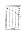
そして、本体部(屈曲部)のゴム硬度の異なる、3種類のワイパーのそれぞれについて、摺動部を被清掃面に対して摺動させたときの、摺動抵抗(摩擦抵抗)を測定した。具体的には、図4に示すように、ガイド31により鉛直方向に案内されたワイパー1を、ステンレス板30に3mm押さえつけて、先端の摺動部3をステンレス板30に接触させた状態で、ステンレス板30を水平方向に移動させた。このときの、ワイパー1に作用する水平方向の力をロードセル32で測定し、これを摺動抵抗とした。図5に、3種類のワイパーの本体部ゴム硬度と、上述の方法によって測定された摺動抵抗(摩擦抵抗)の関係を示す。
Then, the sliding resistance (friction resistance) when the sliding portion was slid with respect to the surface to be cleaned was measured for each of three types of wipers having different rubber hardnesses of the main body portion (bending portion). Specifically, as shown in FIG. 4, the wiper 1 guided in the vertical direction by the
図5に示すように、本体部の硬度(JIS−A硬度)が70°未満になると摺動抵抗が20g/cmを下回ることになるので、摺動部が被清掃面を押さえつける面圧が小さくなり、ワイパーの掻き取り性能の低下につながる。一方、本体部の硬度が85°を超えると、摺動抵抗がかなり大きくなって摺動部がスムーズに摺動することができなくなる。以上より、ワイパーの掻き取り性能を向上させるためには、本体部の硬度は70°〜85°の範囲で設定されることが好ましい。 As shown in FIG. 5, when the hardness of the main body (JIS-A hardness) is less than 70 °, the sliding resistance is less than 20 g / cm, so that the surface pressure at which the sliding portion presses the surface to be cleaned is small. This leads to a decrease in the wiper scraping performance. On the other hand, if the hardness of the main body part exceeds 85 °, the sliding resistance becomes considerably large and the sliding part cannot slide smoothly. As mentioned above, in order to improve the scraping performance of a wiper, it is preferable that the hardness of a main-body part is set in the range of 70 degrees-85 degrees.
(2)摩擦低減材と金属板に対する接着力の関係について
次に、ワイパーの、金属板との接着部分に摩擦低減材としての繊維材料が配合されている場合と、繊維材料が配合されていない場合とで、金属板に対する接着力がどのように変わるかについて、以下のように検証した。
(2) Relationship between the friction reducing material and the adhesive force to the metal plate Next, when the fiber material as the friction reducing material is blended in the bonded portion of the wiper with the metal plate, the fiber material is not blended. It verified as follows about how the adhesive force with respect to a metal plate changes with the case.
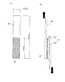
図6(a),(b)は、この検証実験において使用された、金属板20とこの金属板20に接着されたゴム部材21とからなる試料を示している。図6(a)に示すように、金属板20は、長さ125mm、幅25mmの長尺な板である。この金属板20の下端から60mmの部分の表面にブラスト処理を施した後に、接着剤22(東洋化学研究所製、商品名:メタロック、型式:N−15D)を塗布した。
FIGS. 6A and 6B show a sample made of the
また、ゴム部材21としては、主成分のゴムに、繊維材料が配合されたものと、配合されていないものを使用した。このゴム部材のゴム配合(単位:質量部)を表2に示す。
Further, as the
図6に示すように、ゴム部材21は、2つの部分(接合部21aと非接合部21b)が連結された構造を有する。そして、このゴム部材21の一方の部分(接合部21a)を接着剤22によって金属板20に接合した。
As shown in FIG. 6, the
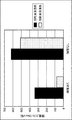
そして、繊維材料が配合された試料と、繊維材料が配合されていない試料のそれぞれについて、図6(b)に示すように、金属板20の上端と、ゴム部材21の非接合部21bの下端をそれぞれ引っ張り、ゴム部材21の接合部21aが金属板20から剥がれるときの引張力を接着力として測定した。さらに、試料を70℃の切削油に28日間浸漬させた後の状態において、同様にして接着力を測定した。その結果を図7に示す。
And about each of the sample with which the fiber material was mix | blended, and the sample with which the fiber material was not mix | blended, as shown in FIG.6 (b), the upper end of the
図7に示すように、ゴム部材21に繊維材料が配合されていない場合には、ゴム部材21に繊維材料が配合されていると比べて、初期接着力(切削油に浸漬される前の接着力)が高い。さらに、繊維材料が配合されていない場合には、切削油に浸漬されたときの、初期接着力に対する接着力の低下も少ない。これらの結果により、ワイパーとフレームとの接着力を高くするためには、フレームに接着される本体部には繊維材料等の摩擦低減材が配合されていないことが好ましいことがわかる。
As shown in FIG. 7, when the fiber material is not blended in the
(3)摺動部の研磨効果について
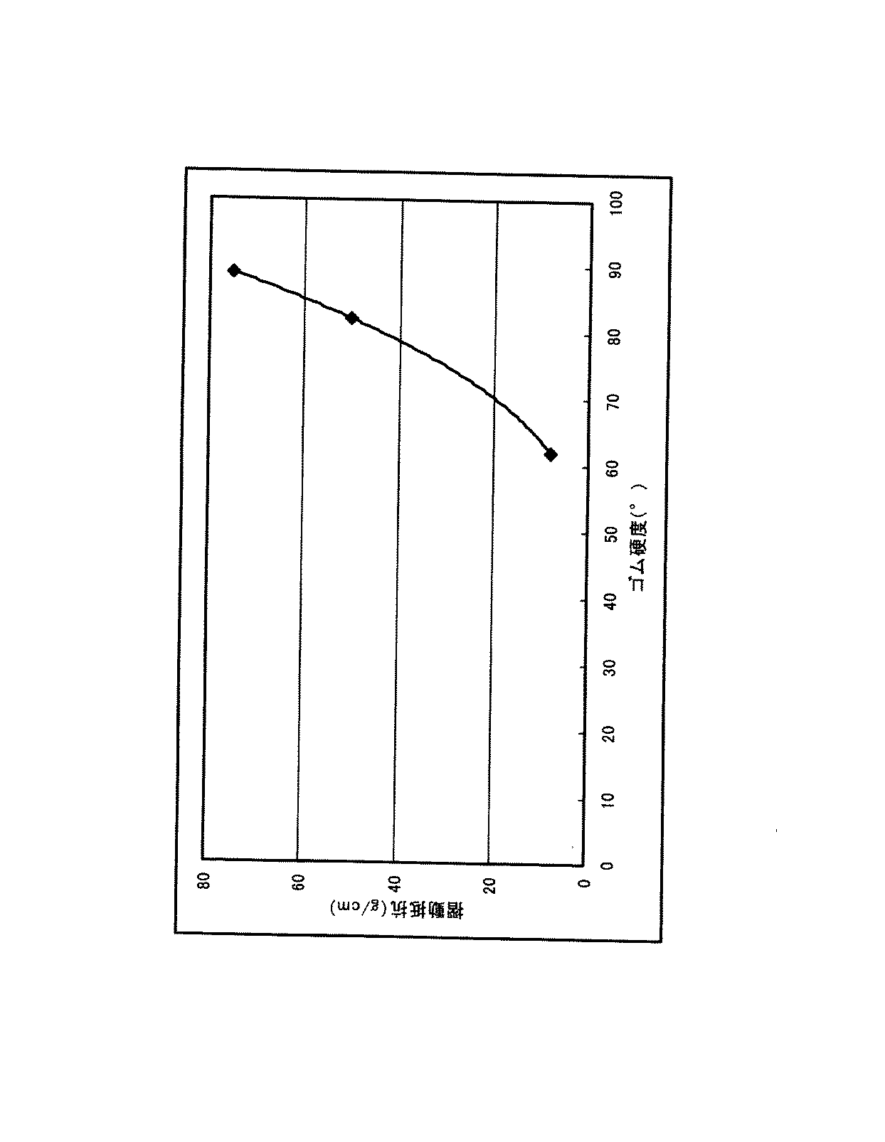
次に、摺動部(特に、被清掃面と接触する接触部)の表面を研磨しない場合と、研磨した場合のそれぞれについて、摺動抵抗(摩擦抵抗)を測定して検証した。ここで、摺動部の研磨は、エンドレス形状のヤスリに摺動部を押し当てて軽く接触させた状態で、ヤスリを4.5m/secの周速で走行させることによって行った。また、摺動抵抗は、前述した図4の方法により測定した。その測定結果を図8に示す。
(3) Regarding the polishing effect of the sliding part Next, the sliding resistance (friction resistance) for each of the case where the surface of the sliding part (particularly the contact part contacting the surface to be cleaned) is not polished and the case where it is polished Was measured and verified. Here, polishing of the sliding portion was performed by running the file at a peripheral speed of 4.5 m / sec in a state where the sliding portion was pressed against the endless file and lightly contacted. The sliding resistance was measured by the method shown in FIG. The measurement results are shown in FIG.
図8に示すように、摺動部の表面を研磨した場合には、研磨しない場合に比べて、摺動抵抗(摩擦抵抗)が約1/4まで低減している。これは、摺動部の研磨によって、摺動部のゴムの表層が取り除かれて、摩擦低減材の露出面積が増大するために、被清掃面と摺動部との間の摩擦抵抗が低減されると考えられる。 As shown in FIG. 8, when the surface of the sliding portion is polished, the sliding resistance (friction resistance) is reduced to about 1/4 compared with the case where the surface is not polished. This is because the surface layer of the rubber of the sliding portion is removed by polishing the sliding portion, and the exposed area of the friction reducing material is increased, so that the frictional resistance between the surface to be cleaned and the sliding portion is reduced. It is thought.
(4)摩擦低減材としての繊維材料の配向方向について
最後に、摩擦低減材として繊維材料を使用したときの、その配向方向による摺動部形状の違いについて調べた。表3に、ワイパーの本体部を構成するゴム組成物のゴム配合と、摺動部を構成するゴム組成物のゴム配合を、それぞれ示す(単位:質量部)。
(4) About orientation direction of fiber material as friction reducing material Finally, when the fiber material was used as a friction reducing material, the difference in the sliding part shape by the orientation direction was investigated. Table 3 shows the rubber composition of the rubber composition constituting the main body portion of the wiper and the rubber composition of the rubber composition constituting the sliding portion (unit: parts by mass).
また、摺動部には、摩擦低減材としてナイロン短繊維を配合した。ここで、ナイロン短繊維を図2のようにワイパーの幅方向と直交する縦方向(被清掃面と交差する方向)に配向したものと、図3のようにワイパーの幅方向(被清掃面と平行な方向)に配向したものを、それぞれ作製した。 Further, nylon short fibers were blended in the sliding portion as a friction reducing material. Here, the nylon short fibers are oriented in the longitudinal direction (direction intersecting the surface to be cleaned) orthogonal to the width direction of the wiper as shown in FIG. 2, and the width direction of the wiper (the surface to be cleaned and the surface to be cleaned) as shown in FIG. Those oriented in a parallel direction) were prepared.
その結果、ナイロン短繊維をワイパーの縦方向に配向したワイパー(図2のワイパー)では、摺動部の被清掃面との接触部は平坦に成形された。しかし、ナイロン短繊維をワイパーの幅方向に配向したワイパー(図3のワイパー)では、摺動部において3mm程度の振れ幅の波打ち形状が発現し、接触部が被清掃面に隙間なく密着することが困難なワイパーとなった。この結果から、摺動部に配合する繊維材料は、ワイパーの被清掃面に交差する方向に配向されていることが好ましい。 As a result, in the wiper in which nylon short fibers were oriented in the longitudinal direction of the wiper (wiper in FIG. 2), the contact portion of the sliding portion with the surface to be cleaned was formed flat. However, in a wiper in which nylon short fibers are oriented in the width direction of the wiper (the wiper in FIG. 3), a wavy shape with a swing width of about 3 mm appears in the sliding portion, and the contact portion adheres closely to the surface to be cleaned without a gap. Became a difficult wiper. From this result, it is preferable that the fiber material blended in the sliding portion is oriented in a direction intersecting the surface to be cleaned of the wiper.
以上、本発明の実施形態の一例について説明したが、本発明を適用可能な形態はこれに限られるものではない。 As mentioned above, although an example of embodiment of this invention was demonstrated, the form which can apply this invention is not restricted to this.
前述した実施形態のワイパーは、硬度の異なる2つの部分(本体部2と摺動部3)が一体化された構造を有するが、硬度が互いに異なる3以上の部分が一体化されたものであってもよい。
The wiper of the above-described embodiment has a structure in which two parts having different hardness (the
また、前述した実施形態のワイパーは自らが被清掃面に対して移動するように構成されているが、ワイパー自身は移動不能に固定されており、被清掃面を有する金属部品がワイパーに対して移動するように構成されていてもよい。 In addition, the wiper of the above-described embodiment is configured so that the wiper itself moves relative to the surface to be cleaned, but the wiper itself is fixed so as not to move, and the metal part having the surface to be cleaned is against the wiper. It may be configured to move.
さらに、本発明の適用対象は、工作機械用の金属屑等を除去するためのワイパーに限られるものではなく、ゴミ等の異物が付着した被清掃面に対して摺動して異物を除去するものであれば、それ以外の分野で用いられるワイパーに本発明を適用することも可能である。 Furthermore, the scope of application of the present invention is not limited to wipers for removing metal scraps for machine tools, but removes foreign objects by sliding against the surface to be cleaned to which foreign objects such as dust adhere. If it is a thing, it is also possible to apply this invention to the wiper used in the field | area other than that.
1 ワイパー
2 本体部
3 摺動部
4 取付部
5 屈曲部
6 フレーム
7 接着剤
8 切欠部
9 接触部
10 被清掃面
11 繊維材料
DESCRIPTION OF SYMBOLS 1
Claims (3)
本体部と、
前記本体部と一体化されるとともに前記被清掃面に接触可能な摺動部とを備え、
前記摺動部には前記被清掃面との間の摩擦抵抗を低減するための摩擦低減材が前記摺動部全体に分散されて配合される一方で、前記被清掃面に接触しない前記本体部には前記摩擦低減材が配合されておらず、
前記摩擦低減材が繊維材料を含み、
前記繊維材料は、前記摺動部内において前記被清掃面と交差する方向であって、ワイパーの幅方向と直交する方向に配向していることを特徴とするワイパー。 A wiper that wipes the surface to be cleaned by sliding against the surface to be cleaned of an object,
The main body,
A slide part that is integrated with the main body part and capable of contacting the surface to be cleaned;
The sliding portion is blended with a friction reducing material for reducing the frictional resistance between the sliding portion and the surface to be cleaned, while being dispersed and blended throughout the sliding portion, the body portion not contacting the surface to be cleaned. Does not contain the friction reducing material,
The friction reducing material comprises a fiber material;
The wiper according to claim 1, wherein the fiber material is oriented in a direction intersecting with the surface to be cleaned in the sliding portion and perpendicular to a width direction of the wiper.
The wiper according to claim 1 or 2, wherein a contact portion of the sliding portion with the surface to be cleaned is polished.
Priority Applications (1)
| Application Number | Priority Date | Filing Date | Title |
|---|---|---|---|
| JP2008077827A JP5531270B2 (en) | 2007-03-28 | 2008-03-25 | Wiper |
Applications Claiming Priority (3)
| Application Number | Priority Date | Filing Date | Title |
|---|---|---|---|
| JP2007085222 | 2007-03-28 | ||
| JP2007085222 | 2007-03-28 | ||
| JP2008077827A JP5531270B2 (en) | 2007-03-28 | 2008-03-25 | Wiper |
Publications (2)
| Publication Number | Publication Date |
|---|---|
| JP2008264776A JP2008264776A (en) | 2008-11-06 |
| JP5531270B2 true JP5531270B2 (en) | 2014-06-25 |
Family
ID=40045029
Family Applications (1)
| Application Number | Title | Priority Date | Filing Date |
|---|---|---|---|
| JP2008077827A Active JP5531270B2 (en) | 2007-03-28 | 2008-03-25 | Wiper |
Country Status (1)
| Country | Link |
|---|---|
| JP (1) | JP5531270B2 (en) |
Cited By (1)
| Publication number | Priority date | Publication date | Assignee | Title |
|---|---|---|---|---|
| JP2020032336A (en) * | 2018-08-28 | 2020-03-05 | 三ツ星ベルト株式会社 | Wiper |
Families Citing this family (6)
| Publication number | Priority date | Publication date | Assignee | Title |
|---|---|---|---|---|
| JP2012183468A (en) * | 2011-03-04 | 2012-09-27 | Toshio Goto | Apparatus for scraping and removing solid deposit |
| JP2014008575A (en) * | 2012-06-29 | 2014-01-20 | Mitsuboshi Belting Ltd | Wiper and method of manufacturing the same |
| CN105722638B (en) * | 2013-12-26 | 2018-12-04 | 霓达株式会社 | Scraping brushing device and its manufacturing method |
| JP2017001177A (en) * | 2015-06-11 | 2017-01-05 | ニッタ株式会社 | Industrial wiper and wiping method |
| JP6088084B2 (en) * | 2016-03-18 | 2017-03-01 | 三ツ星ベルト株式会社 | Manufacturing method of wiper |
| JP7000086B2 (en) | 2017-09-12 | 2022-01-19 | ニッタ株式会社 | How to manufacture wipers for machine tools and wipers for machine tools |
Family Cites Families (5)
| Publication number | Priority date | Publication date | Assignee | Title |
|---|---|---|---|---|
| JPS599231B2 (en) * | 1977-12-16 | 1984-03-01 | 三菱鉱業セメント株式会社 | Plug moving in pipeline |
| JP3050875U (en) * | 1997-11-11 | 1998-08-07 | 日本ジャバラ工業株式会社 | A wiper device that combines two resin materials. |
| JP3193361B2 (en) * | 1999-04-07 | 2001-07-30 | ニッタ株式会社 | Wipers for machine tools |
| JP2007050459A (en) * | 2005-08-17 | 2007-03-01 | Mitsuboshi Belting Ltd | Dustproof member, die for manufacturing elastic member, and manufacturing method of elastic member |
| JP2007083344A (en) * | 2005-09-22 | 2007-04-05 | Nitta Ind Corp | Industrial wiper |
-
2008
- 2008-03-25 JP JP2008077827A patent/JP5531270B2/en active Active
Cited By (1)
| Publication number | Priority date | Publication date | Assignee | Title |
|---|---|---|---|---|
| JP2020032336A (en) * | 2018-08-28 | 2020-03-05 | 三ツ星ベルト株式会社 | Wiper |
Also Published As
| Publication number | Publication date |
|---|---|
| JP2008264776A (en) | 2008-11-06 |
Similar Documents
| Publication | Publication Date | Title |
|---|---|---|
| JP5531270B2 (en) | Wiper | |
| JP2008537996A (en) | Test method and apparatus for rubber tire and solid rubber wheel test chamber sample | |
| JP6482472B2 (en) | Wiper blade rubber coating agent and wiper blade rubber using the same | |
| CN1120765C (en) | Wiper for machine tool | |
| KR102428063B1 (en) | wiper blade rubber | |
| JP5192849B2 (en) | Wiper | |
| JPH11506071A (en) | Wiper blade | |
| JP2007083344A (en) | Industrial wiper | |
| JP6943823B2 (en) | Wiper | |
| JP6088084B2 (en) | Manufacturing method of wiper | |
| JP2017001176A (en) | Industrial wiper, method for production thereof, and wiping method | |
| JP2014008575A (en) | Wiper and method of manufacturing the same | |
| JP6454198B2 (en) | Wiper | |
| JP2003182531A (en) | Wiper blade rubber with surface roughening treatment and wiper device | |
| JP2014034599A (en) | Wiper blade rubber | |
| JP3554754B2 (en) | Friction material and friction device | |
| JPH0446849A (en) | Wiper blade rubber | |
| JP2002046040A (en) | Scraper for machine tool | |
| WO2024071174A1 (en) | Blade rubber regeneration device, blade rubber regeneration method, and regenerated blade rubber manufacturing method | |
| JP2019064281A (en) | Wiper blade rubber | |
| WO2024071206A1 (en) | Blade rubber regeneration device, blade rubber regeneration method, and method for manufacturing regenerated blade rubber | |
| WO2024071181A1 (en) | Recovery apparatus for blade rubber, recovery method for blade rubber, and manufacturing method for recovery blade rubber | |
| JP2005066376A (en) | Wiper for industrial use | |
| EP4257251A1 (en) | Wiper | |
| US10207682B2 (en) | Rubber wiper blade element with friction reducing agent that continuously migrates to the surface |
Legal Events
| Date | Code | Title | Description |
|---|---|---|---|
| A621 | Written request for application examination |
Free format text: JAPANESE INTERMEDIATE CODE: A621 Effective date: 20110203 |
|
| A977 | Report on retrieval |
Free format text: JAPANESE INTERMEDIATE CODE: A971007 Effective date: 20120531 |
|
| A131 | Notification of reasons for refusal |
Free format text: JAPANESE INTERMEDIATE CODE: A131 Effective date: 20120619 |
|
| A521 | Request for written amendment filed |
Free format text: JAPANESE INTERMEDIATE CODE: A523 Effective date: 20120803 |
|
| A131 | Notification of reasons for refusal |
Free format text: JAPANESE INTERMEDIATE CODE: A131 Effective date: 20130122 |
|
| A521 | Request for written amendment filed |
Free format text: JAPANESE INTERMEDIATE CODE: A523 Effective date: 20130306 |
|
| A131 | Notification of reasons for refusal |
Free format text: JAPANESE INTERMEDIATE CODE: A131 Effective date: 20130924 |
|
| A521 | Request for written amendment filed |
Free format text: JAPANESE INTERMEDIATE CODE: A523 Effective date: 20131001 |
|
| TRDD | Decision of grant or rejection written | ||
| A01 | Written decision to grant a patent or to grant a registration (utility model) |
Free format text: JAPANESE INTERMEDIATE CODE: A01 Effective date: 20140325 |
|
| A61 | First payment of annual fees (during grant procedure) |
Free format text: JAPANESE INTERMEDIATE CODE: A61 Effective date: 20140327 |
|
| R150 | Certificate of patent or registration of utility model |
Ref document number: 5531270 Country of ref document: JP Free format text: JAPANESE INTERMEDIATE CODE: R150 |
|
| R250 | Receipt of annual fees |
Free format text: JAPANESE INTERMEDIATE CODE: R250 |
|
| R250 | Receipt of annual fees |
Free format text: JAPANESE INTERMEDIATE CODE: R250 |
|
| R250 | Receipt of annual fees |
Free format text: JAPANESE INTERMEDIATE CODE: R250 |
|
| R250 | Receipt of annual fees |
Free format text: JAPANESE INTERMEDIATE CODE: R250 |
|
| R250 | Receipt of annual fees |
Free format text: JAPANESE INTERMEDIATE CODE: R250 |