EP1199127A2 - Underwater laser processing apparatus and underwater laser processing method - Google Patents
Underwater laser processing apparatus and underwater laser processing method Download PDFInfo
- Publication number
- EP1199127A2 EP1199127A2 EP01122593A EP01122593A EP1199127A2 EP 1199127 A2 EP1199127 A2 EP 1199127A2 EP 01122593 A EP01122593 A EP 01122593A EP 01122593 A EP01122593 A EP 01122593A EP 1199127 A2 EP1199127 A2 EP 1199127A2
- Authority
- EP
- European Patent Office
- Prior art keywords
- workpiece
- nozzle
- gas
- underwater
- laser beam
- Prior art date
- Legal status (The legal status is an assumption and is not a legal conclusion. Google has not performed a legal analysis and makes no representation as to the accuracy of the status listed.)
- Granted
Links
Images



Classifications
-
- B—PERFORMING OPERATIONS; TRANSPORTING
- B23—MACHINE TOOLS; METAL-WORKING NOT OTHERWISE PROVIDED FOR
- B23K—SOLDERING OR UNSOLDERING; WELDING; CLADDING OR PLATING BY SOLDERING OR WELDING; CUTTING BY APPLYING HEAT LOCALLY, e.g. FLAME CUTTING; WORKING BY LASER BEAM
- B23K26/00—Working by laser beam, e.g. welding, cutting or boring
- B23K26/14—Working by laser beam, e.g. welding, cutting or boring using a fluid stream, e.g. a jet of gas, in conjunction with the laser beam; Nozzles therefor
- B23K26/1462—Nozzles; Features related to nozzles
- B23K26/1464—Supply to, or discharge from, nozzles of media, e.g. gas, powder, wire
- B23K26/1476—Features inside the nozzle for feeding the fluid stream through the nozzle
-
- B—PERFORMING OPERATIONS; TRANSPORTING
- B23—MACHINE TOOLS; METAL-WORKING NOT OTHERWISE PROVIDED FOR
- B23K—SOLDERING OR UNSOLDERING; WELDING; CLADDING OR PLATING BY SOLDERING OR WELDING; CUTTING BY APPLYING HEAT LOCALLY, e.g. FLAME CUTTING; WORKING BY LASER BEAM
- B23K26/00—Working by laser beam, e.g. welding, cutting or boring
- B23K26/02—Positioning or observing the workpiece, e.g. with respect to the point of impact; Aligning, aiming or focusing the laser beam
-
- B—PERFORMING OPERATIONS; TRANSPORTING
- B23—MACHINE TOOLS; METAL-WORKING NOT OTHERWISE PROVIDED FOR
- B23K—SOLDERING OR UNSOLDERING; WELDING; CLADDING OR PLATING BY SOLDERING OR WELDING; CUTTING BY APPLYING HEAT LOCALLY, e.g. FLAME CUTTING; WORKING BY LASER BEAM
- B23K26/00—Working by laser beam, e.g. welding, cutting or boring
- B23K26/02—Positioning or observing the workpiece, e.g. with respect to the point of impact; Aligning, aiming or focusing the laser beam
- B23K26/03—Observing, e.g. monitoring, the workpiece
-
- B—PERFORMING OPERATIONS; TRANSPORTING
- B23—MACHINE TOOLS; METAL-WORKING NOT OTHERWISE PROVIDED FOR
- B23K—SOLDERING OR UNSOLDERING; WELDING; CLADDING OR PLATING BY SOLDERING OR WELDING; CUTTING BY APPLYING HEAT LOCALLY, e.g. FLAME CUTTING; WORKING BY LASER BEAM
- B23K26/00—Working by laser beam, e.g. welding, cutting or boring
- B23K26/02—Positioning or observing the workpiece, e.g. with respect to the point of impact; Aligning, aiming or focusing the laser beam
- B23K26/03—Observing, e.g. monitoring, the workpiece
- B23K26/032—Observing, e.g. monitoring, the workpiece using optical means
-
- B—PERFORMING OPERATIONS; TRANSPORTING
- B23—MACHINE TOOLS; METAL-WORKING NOT OTHERWISE PROVIDED FOR
- B23K—SOLDERING OR UNSOLDERING; WELDING; CLADDING OR PLATING BY SOLDERING OR WELDING; CUTTING BY APPLYING HEAT LOCALLY, e.g. FLAME CUTTING; WORKING BY LASER BEAM
- B23K26/00—Working by laser beam, e.g. welding, cutting or boring
- B23K26/02—Positioning or observing the workpiece, e.g. with respect to the point of impact; Aligning, aiming or focusing the laser beam
- B23K26/06—Shaping the laser beam, e.g. by masks or multi-focusing
- B23K26/064—Shaping the laser beam, e.g. by masks or multi-focusing by means of optical elements, e.g. lenses, mirrors or prisms
- B23K26/0648—Shaping the laser beam, e.g. by masks or multi-focusing by means of optical elements, e.g. lenses, mirrors or prisms comprising lenses
-
- B—PERFORMING OPERATIONS; TRANSPORTING
- B23—MACHINE TOOLS; METAL-WORKING NOT OTHERWISE PROVIDED FOR
- B23K—SOLDERING OR UNSOLDERING; WELDING; CLADDING OR PLATING BY SOLDERING OR WELDING; CUTTING BY APPLYING HEAT LOCALLY, e.g. FLAME CUTTING; WORKING BY LASER BEAM
- B23K26/00—Working by laser beam, e.g. welding, cutting or boring
- B23K26/02—Positioning or observing the workpiece, e.g. with respect to the point of impact; Aligning, aiming or focusing the laser beam
- B23K26/06—Shaping the laser beam, e.g. by masks or multi-focusing
- B23K26/0665—Shaping the laser beam, e.g. by masks or multi-focusing by beam condensation on the workpiece, e.g. for focusing
-
- B—PERFORMING OPERATIONS; TRANSPORTING
- B23—MACHINE TOOLS; METAL-WORKING NOT OTHERWISE PROVIDED FOR
- B23K—SOLDERING OR UNSOLDERING; WELDING; CLADDING OR PLATING BY SOLDERING OR WELDING; CUTTING BY APPLYING HEAT LOCALLY, e.g. FLAME CUTTING; WORKING BY LASER BEAM
- B23K26/00—Working by laser beam, e.g. welding, cutting or boring
- B23K26/12—Working by laser beam, e.g. welding, cutting or boring in a special environment or atmosphere, e.g. in an enclosure
- B23K26/1224—Working by laser beam, e.g. welding, cutting or boring in a special environment or atmosphere, e.g. in an enclosure in vacuum
-
- B—PERFORMING OPERATIONS; TRANSPORTING
- B23—MACHINE TOOLS; METAL-WORKING NOT OTHERWISE PROVIDED FOR
- B23K—SOLDERING OR UNSOLDERING; WELDING; CLADDING OR PLATING BY SOLDERING OR WELDING; CUTTING BY APPLYING HEAT LOCALLY, e.g. FLAME CUTTING; WORKING BY LASER BEAM
- B23K26/00—Working by laser beam, e.g. welding, cutting or boring
- B23K26/12—Working by laser beam, e.g. welding, cutting or boring in a special environment or atmosphere, e.g. in an enclosure
- B23K26/123—Working by laser beam, e.g. welding, cutting or boring in a special environment or atmosphere, e.g. in an enclosure in an atmosphere of particular gases
-
- B—PERFORMING OPERATIONS; TRANSPORTING
- B23—MACHINE TOOLS; METAL-WORKING NOT OTHERWISE PROVIDED FOR
- B23K—SOLDERING OR UNSOLDERING; WELDING; CLADDING OR PLATING BY SOLDERING OR WELDING; CUTTING BY APPLYING HEAT LOCALLY, e.g. FLAME CUTTING; WORKING BY LASER BEAM
- B23K26/00—Working by laser beam, e.g. welding, cutting or boring
- B23K26/14—Working by laser beam, e.g. welding, cutting or boring using a fluid stream, e.g. a jet of gas, in conjunction with the laser beam; Nozzles therefor
Definitions
- the present invention relates to an underwater laser processing apparatus and an underwater laser processing method, and more particularly, to an apparatus and a method capable of repairing or welding cracks in a structure underwater using a laser beam for maintaining stability and safety thereof.
- Such cracks must be repaired immediately, such as to remove the cracks completely by using a grinder and the like and then weld fillers on the cracks. In order to restrain the growth of cracks, it is important to isolate the cracks from the atmosphere. Sealing up the crack openings with fillers is one effective method.
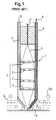
- Fig. 1 is a sectional view showing an exemplary laser repairing apparatus.
- an optical unit 3 having lenses 2 is secured.
- a laser beam 5 guided to the optical head 1 by an optical fiber 4 is condensed by the optical unit 3, and is irradiated from the top of the optical head 1 to the part to be welded in a work or workpiece 6 such as a pipe.
- the top of the optical head 1 is formed as a thin nozzle 7 capable of approaching close to a laser spot.
- a welding wire 8 is provided to the laser spot by a wire feeding path 9, and shield gas 10 is supplied by a gas source (not shown) to the nozzle 7 by a gas feeding path 11.
- the laser beam 5 oscillated by a YAG laser is guided to the optical head 1 disposed under water 12 via the optical fiber 4, and the laser beam 5 condensed by the optical unit 3 is irradiated to the workpiece 6.
- the welding wire 8 is supplied to the laser spot via the wire feeding path 9.
- the shield gas 10 is supplied to the nozzle 7, via the gas feeding path 11, and is injected from the top of the nozzle 7 to the laser spot. In this process, water is excluded from the point to be welded by the injected shield gas 10 and the gas atmosphere 13 allows the welding process to be generated. Note that the shield gas 10 can keep the dried condition of the welding wire 8.
- the shield gas 10 has to be supplied continuously and water has to be excluded to form the gas atmosphere 13.
- the optical head 1 is tapered at the top, and if a certain volume of bubbles 13a are created, the same amount of water around the nozzle 7 enters the optical head 1 easily. Thereby, it is difficult to maintain the gas atmosphere 13.
- maintaining the gas atmosphere 13 is much more difficult and the above problem may be exacerbated.
- the present invention addresses of the above-mentioned circumstances and is intended to solve the above-mentioned problems.
- the purpose of the present invention is to provide an underwater laser processing apparatus and an underwater laser processing method capable of generating a stable gas atmosphere around a work or workpiece being processed, and thereby realize an underwater laser process of better quality.
- the present invention provides an underwater laser processing apparatus, including: an optical unit that irradiates a condensed laser beam generated by a laser source to a certain point of an underwater workpiece; and a nozzle having a gas exit for supplying a gas to the certain point, wherein the nozzle has an area surrounding the gas exit extending to the surface of the workpiece for keeping the supplied gas between the nozzle and the workpiece.
- the present invention further provides an underwater laser processing method, including: irradiating a condensed laser beam generated by a laser source to a certain point of an underwater workpiece; and supplying a gas to the certain point from a nozzle, having a gas exit and an area surrounding the gas exit, and extending to the surface of the workpiece for keeping the supplied gas between the nozzle, and the work.
- the present invention also provides an underwater laser processing apparatus, including: means for irradiating a condensed laser beam generated by a laser source to a certain point of an underwater workpiece; and a supplying means for supplying gas to the certain point, wherein the supplying means has an area surrounding the gas exit and extending to the surface of the workpiece for keeping the supplied gas between the nozzle and the workpiece.
- Fig. 1 is a sectional view showing an optical head of a conventional underwater laser processing apparatus.
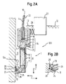
- Fig. 2A is a sectional view showing an optical head and Fig. 2B is a sectional view showing the tip portion of the optical head according to a first embodiment of the present invention.
- Fig. 3A is a schematic diagram showing the structure above the optical head and Fig. 3B is a side view showing a mechanism supporting the optical head according to the first embodiment of the present invention.
- Figs. 4A and 4B are sectional views showing nozzles of the present invention.
- Fig. 5 is a chart showing a process condition according to the first embodiment of the present invention.
- Fig. 6 is a flow chart showing a process method including the present invention.
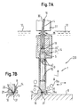
- Fig. 7A is a sectional view showing an optical head and Fig. 7B is a sectional view showing the tip portion of the optical head according to a second embodiment of the present invention.
- Fig. 8A is a sectional view of an optical head and Fig. 8B is a sectional view of an optical head around a dichroic mirror according to a third embodiment of the present invention.
- Fig. 2A is a sectional view showing an underwater laser processing apparatus according to a first embodiment of the present invention.
- the underwater laser processing apparatus 100 is operated below a water surface 12 and is equipped with an optical head 1.
- the optical head 1 includes an optical unit 3 having an optical fiber 4, a plurality of collimator lenses 15, and a condenser lens 16 in that order.
- a welding wire feeder 14 supplies a welding wire 8 through the optical head 1.
- the optical unit 3 is arranged parallel to a laser beam 5 guided by the optical fiber 4 connected to a laser oscillator (not shown in Fig. 2A), and the collimator or condenser lens 16 condenses the parallel laser beam to a weld 31 on a work or workpiece 6 to be processed.
- a reflecting mirror 17 is secured in the bottom of the optical head 1 and reflects the condensed laser beam.
- the laser beam 5 is irradiated to the workpiece 6 with its axis inclined at an angle of about 10 to 20 degrees. This avoids entry of a reflected laser beam into the laser oscillator through the optical head 1.
- a bush 18 is disposed on the end portion of the optical fiber 4 or the end portion of the optical head 1. This can also avoid entrance of the reflected laser beam into the laser oscillator to prevent damage to the laser oscillator.
- the welding wire feeder 14 for feeding the welding wire 8 includes a reel 20 that stores the welding wire 8, a motor 22 that supplies the welding wire 8 from the reel 20, and a feeder pipe 23 that guides the welding wire 8. As shown in detail in Fig. 2B, the welding wire feeder 14 also includes a wire tip 24 disposed at the end of the optical head 1. The wire tip 24 is preferably fixed to the feeder pipe 23 by brazing. The motor 22 drives rollers 21 to supply the welding wire 8 to the feeder pipe 23, and the welding wire 8 is sent to the weld 31 via the wire tip 24.
- a laser oscillator 35 such as a YAG (yttrium aluminum garnet) laser oscillator and a process machine 27 are disposed mainly upstream of the optical head 1.
- the laser oscillator 35 is disposed in atmosphere (air) together with a gas source 32 supplying gas to the optical head 1.
- the laser oscillator 35 and the optical head 1 is connected by the optical fiber 4 to guide the YAG laser beam.
- the optical fiber 4 has an outside guard tube 30, and a shield gas 10 from the gas source 32 is sent to the optical head 1 by using the outside guard tube 30. This structure makes it possible to omit separate tubes especially for the shield gas 10.
- a process machine 27 has a rotor 37 supported by a beam 36 above the workpiece 6 having a cylindrical shape, a horizontal slider 38 connected to the axis of the rotor 37 to allow movement along radial direction of the workpiece 6, and a vertical slider 39 connected to the top of the horizontal slider 38 to allow movement along an axial direction of the workpiece 6.
- the optical head 1 is connected to the lower end of the vertical slider 39.
- the optical head 1 is roughly positioned near the weld 31.
- Suction pads 40 disposed on the lower end of the vertical slider 39 fix the vertical slider 39 to the workpiece 6, and the optical head 1 is positioned precisely by a folding arm 41. After the positioning, the optical head 1 is used to process (repairing, welding or the like) the workpiece 6 by driving a two-axial slider 42.
- the optical head 1 connects a gap adjuster such as a sliding member 26 on the side of a nozzle 29.
- the optical head 1 and the process machine 27 are connected with a spring 28. Even if the work 6 has an uneven surface, the optical head 1 can keep a certain gap between the nozzle 29 and the workpiece 6 by elasticity of the spring 28. The gap is controlled to keep underwater laser processing stable.
- nozzle 29 of the present invention is shown in Figs. 4A and 4B.
- the nozzle 29 is connected to the end of the optical head 1, and is shaped like a disk.
- a hole 25 for supplying the gas and the welding wire is provided in the middle of the nozzle 29.
- the surface area of the nozzle 29 facing the workpiece 6 can be increased. This can maintain a larger amount of gas between the nozzle 29 and the workpiece 6, and a gas atmosphere 13 can be generated and maintained during the laser process as shown in Fig. 2A.
- the span 33 it is preferable to choose the span 33 to be more than 1.5 mm.
- Fig. 4B it is also possible to form circular grooves 34 on the surface of the nozzle 29 facing the workpiece 6.
- the section of the groove 34 may be rectangular, triangular, semicircular or the like.
- supplying gas to the nozzle exhausts the gas as the bubbles and the same amount of water around the nozzle is enters to the optical head 1.
- the groove 34 acts as a resistance against water 12, even if a bubble 13a is generated, and the gas atmosphere 13 can be maintained.
- a process condition on the underwater laser process is shown in Fig. 5.
- a wavelength of 1.06 ⁇ m, an output power of between 0.5 and 4.0 kW, a process speed of between 0.1 and 5.0 m/min, a welding wire diameter of between 0.4 and 1.0 mm, and a wire feeding speed of between 0.5 and 8.0 m/min can preferably be used to achieve stable underwater laser repair/weld processing.
- a flow diagram of the underwater laser repair/weld process is shown.
- the reactor may have slugs and oxidation films on its surface. Therefore, to achieve a stable underwater process, removing slugs and oxidation films beforehand is necessary.
- slugs are removed by using a wire brush, a grinder or the like (S101).
- oxidation films are removed by using a laser beam or the like (S102).
- cracks are repaired/welded by using a laser beam (S103).
- the removing processes S101 and S102 are executed underwater, as well as the process S103 of the present invention.
- the wire feeder 14 can smoothly supply the welding wire 8. Further, because the welding wire 8 is guided by the wire tip 24, it is possible to supply the welding wire 8 to the weld 31 directly without dampness. In addition, since the wire tip 24 is disposed inside a nozzle hole 25, the welding wire 8 can be dried by the shield gas 10 that is supplied to the weld 31.
- the first embodiment of the present invention it is possible to generate a stable gas atmosphere at a processing point on the workpiece, and thereby realizing an underwater laser process of better quality.
- Fig. 7A is sectional view showing an optical head according to a second embodiment of the present invention.
- the basic feature of the optical head 1 of the underwater laser processing apparatus 200 of the second embodiment is similar to the first embodiment. Because the reflecting mirror 17 of the first embodiment is omitted, the optical head 1 of the second embodiment can repair/weld a horizontal surface of the work 6. Considering gravity, this posture of the optical head 1 is preferable to keep the gas atmosphere 13 stable. Furthermore, because a roller 26a is used as a gap adjuster, instead of the slider of the first embodiment, the optical head 1 can move along the surface of the work 6 with little friction.
- Fig. 8A is a sectional view of an optical head according to a third embodiment of the present invention.
- a dichroic mirror 43 is disposed between the collimator lenses 15 and the condenser lens 16, and is inclined at an angle of 45 degrees to the light path.
- the dichroic mirror 43 allows transmission of the laser beam, but separates visible light by way of reflection.
- another condenser lens 44 and a charge coupled device (CCD) camera 45 used as an image sensor are disposed downstream of the reflected light path.
- the CCD camera 45 can be radiation resistant.
- the condition of the weld 31 before and during processing can be recognized by inputting the reflected visible light from the dichroic mirror 43 to the CCD camera 45.
- the recognition of the weld 31 before processing is valuable to improve precision of position of the weld 31.
Landscapes
- Physics & Mathematics (AREA)
- Optics & Photonics (AREA)
- Engineering & Computer Science (AREA)
- Plasma & Fusion (AREA)
- Mechanical Engineering (AREA)
- Laser Beam Processing (AREA)
Abstract
Description
Claims (20)
- An underwater laser processing apparatus, comprising:wherein the nozzle comprises an area surrounding the gas exit extending to the surface of the workpiece for keeping the supplied gas between the nozzle and the workpiece.an optical unit that irradiates a condensed laser beam generated by a laser source to a certain point of an underwater workpiece; anda nozzle having a gas exit for supplying gas to the certain point,
- The apparatus according to claim 1, wherein a nozzle is formed as a disk having the gas exit at the center thereof.
- The apparatus according to claim 2, wherein a diameter of the nozzle exceeds the diameter of the exit by more than approximately 1.5 mm.
- The apparatus according to claim 2, wherein the nozzle has a circular groove on the surface facing the workpiece.
- The apparatus according to claim 1, further comprising a welding wire exit that supplies a welding wire to the certain point.
- The apparatus according to claim 5, wherein the welding wire exit is a wire tip disposed in the nozzle.
- The apparatus according to claim 1, wherein the optical unit irradiates the laser beam at an angle to the workpiece.
- The apparatus according to claim 1, further comprising a bush that prevents a reflected laser beam from entering the laser source.
- The apparatus according to claim 1, wherein the optical unit comprises a collimator lens that makes parallel the laser beam from the laser source, and a condenser lens that condenses the parallel laser beam.
- The apparatus according to claim 9, further comprising a dichroic mirror that separates visible light from the laser beam and inputs the separated visible light to an image sensor.
- The apparatus according to claim 1, further comprising an adjuster that adjusts a gap between the nozzle and the workpiece.
- The apparatus according to claim 11, wherein the adjuster comprises a roller that rolls on the workpiece.
- An underwater laser processing method, comprising:irradiating a condensed laser beam generated by a laser source to a certain point of an underwater workpiece; andsupplying gas to the certain point from a nozzle having a gas exit, the nozzle having an area surrounding the gas exit that extends to the surface of the workpiece for keeping the supplied gas between the nozzle and the workpiece.
- The method according to claim 13, wherein the nozzle is formed as a disk having the gas exit at the center thereof.
- The method according to claim 13, wherein the nozzle has a circular groove on the surface facing the workpiece.
- The method according to claim 13, further comprising supplying a welding wire to the certain point.
- The method according to claim 13, wherein the irradiating step irradiates the laser beam at an angle to the workpiece.
- The method according to claim 13, further comprising separating visible light by a dichroic mirror, and inputting the separated visible light to an image sensor.
- The method according to claim 13, further comprising adjusting a gap between the nozzle and the workpiece.
- An underwater laser processing apparatus, comprising:wherein the means for supplying gas has an area surrounding a gas exit and extending to the surface of the workpiece for keeping the supplied gas between the nozzle and the workpiece.means for irradiating a condensed laser beam generated by a laser source to a certain point of an underwater workpiece; andmeans for supplying gas to the certain point,
Applications Claiming Priority (2)
| Application Number | Priority Date | Filing Date | Title |
|---|---|---|---|
| JP2000295818 | 2000-09-28 | ||
| JP2000295818A JP4155489B2 (en) | 2000-09-28 | 2000-09-28 | Underwater laser repair welding equipment |
Publications (3)
| Publication Number | Publication Date |
|---|---|
| EP1199127A2 true EP1199127A2 (en) | 2002-04-24 |
| EP1199127A3 EP1199127A3 (en) | 2003-10-29 |
| EP1199127B1 EP1199127B1 (en) | 2008-03-05 |
Family
ID=18778187
Family Applications (1)
| Application Number | Title | Priority Date | Filing Date |
|---|---|---|---|
| EP01122593A Expired - Lifetime EP1199127B1 (en) | 2000-09-28 | 2001-09-26 | Underwater laser processing apparatus and underwater laser processing method |
Country Status (4)
| Country | Link |
|---|---|
| US (2) | US6946618B2 (en) |
| EP (1) | EP1199127B1 (en) |
| JP (1) | JP4155489B2 (en) |
| DE (1) | DE60133072T2 (en) |
Families Citing this family (21)
| Publication number | Priority date | Publication date | Assignee | Title |
|---|---|---|---|---|
| FR2826893B1 (en) * | 2001-07-05 | 2003-09-19 | Snecma Moteurs | MINIATURIZED LASER BEAM WELDING APPARATUS |
| US7030337B2 (en) * | 2003-12-19 | 2006-04-18 | Honeywell International, Inc. | Hand-held laser welding wand having removable filler media delivery extension tips |
| JP4383920B2 (en) * | 2004-02-16 | 2009-12-16 | 株式会社東芝 | In-furnace maintenance and repair equipment |
| FR2876933B1 (en) * | 2004-10-25 | 2008-05-09 | Snecma Moteurs Sa | NOZZLE FOR DRILLING HEAD OR MACHINING WITH LASER BEAM |
| JP4585305B2 (en) * | 2004-12-24 | 2010-11-24 | 三菱重工業株式会社 | Method and apparatus for reproducing defect portion |
| JP4846392B2 (en) * | 2006-02-28 | 2011-12-28 | 株式会社東芝 | Underwater repair welding method |
| US7835221B2 (en) | 2006-07-06 | 2010-11-16 | Westerngeco L.L.C. | Optical methods and systems in marine seismic surveying |
| DE602006007580D1 (en) * | 2006-08-07 | 2009-08-13 | Lvd Co | Arrangement and method for on-line monitoring of the laser process of a workpiece using a heat chamber detector and a tilted mirror |
| US7611421B2 (en) * | 2007-02-08 | 2009-11-03 | Samuel Brewer | Golf club handgrip elevation apparatus |
| US7676327B2 (en) | 2007-04-26 | 2010-03-09 | Westerngeco L.L.C. | Method for optimal wave field separation |
| EP2283961A4 (en) | 2008-04-14 | 2017-02-01 | Kabushiki Kaisha Toshiba | Laser welding device and laser welding method |
| US9207347B2 (en) * | 2008-07-05 | 2015-12-08 | Westerngeco L.L.C. | Determining the structure of a towed seismic spread element |
| JP5997965B2 (en) * | 2011-08-09 | 2016-09-28 | 株式会社アマダホールディングス | Laser processing head |
| JP5767900B2 (en) * | 2011-08-24 | 2015-08-26 | 株式会社東芝 | Underwater welding apparatus and method |
| US10307864B2 (en) * | 2013-12-13 | 2019-06-04 | Avonisys Ag | Methods and systems to keep a work piece surface free from liquid accumulation while performing liquid-jet guided laser based material processing |
| US11344975B2 (en) * | 2015-04-09 | 2022-05-31 | Siemens Energy, Inc. | Optically conductive filler for laser processing |
| US10307803B2 (en) * | 2016-07-20 | 2019-06-04 | The United States Of America As Represented By Secretary Of The Navy | Transmission window cleanliness for directed energy devices |
| KR102075731B1 (en) * | 2018-09-27 | 2020-02-10 | 한국기계연구원 | Laser decontamination system |
| JP7610965B2 (en) * | 2020-12-14 | 2025-01-09 | 株式会社Subaru | Laser peening processing apparatus and laser peening processing method |
| US20240045056A1 (en) * | 2022-08-02 | 2024-02-08 | Garmin International, Inc. | Sonar dive ranging system |
| KR102825963B1 (en) * | 2022-11-29 | 2025-06-26 | 한국기계연구원 | Laser watertight case and underwater laser cutting apparatus |
Family Cites Families (16)
| Publication number | Priority date | Publication date | Assignee | Title |
|---|---|---|---|---|
| US3632955A (en) * | 1967-08-31 | 1972-01-04 | Western Electric Co | Simultaneous multiple lead bonding |
| US4151393A (en) * | 1978-02-13 | 1979-04-24 | The United States Of America As Represented By The Secretary Of The Navy | Laser pile cutter |
| EP0287032B1 (en) * | 1987-04-13 | 1996-02-28 | Nec Corporation | Optical alignment system |
| DE4402000C2 (en) * | 1994-01-25 | 1996-04-11 | Fraunhofer Ges Forschung | Nozzle arrangement for laser beam cutting |
| DE4433675A1 (en) * | 1994-09-21 | 1996-03-28 | Fraunhofer Ges Forschung | Compact laser processing head for laser material processing |
| JP3119090B2 (en) * | 1994-10-05 | 2000-12-18 | 株式会社日立製作所 | Underwater laser processing device and underwater construction method using the device |
| CA2168413C (en) * | 1995-01-31 | 2000-04-18 | Kouki Okazaki | Underwater laser processing method and apparatus |
| DE19519725C2 (en) * | 1995-05-30 | 1997-07-03 | Geesthacht Gkss Forschung | Device for welding and / or treating workpieces using laser light in water |
| JP3621753B2 (en) | 1995-06-27 | 2005-02-16 | 石川島播磨重工業株式会社 | Underwater laser welding equipment |
| JP3619286B2 (en) * | 1995-06-27 | 2005-02-09 | 石川島播磨重工業株式会社 | Underwater laser welding equipment |
| TW320586B (en) * | 1995-11-24 | 1997-11-21 | Hitachi Ltd | |
| US6060686A (en) * | 1996-10-15 | 2000-05-09 | General Electric Company | Underwater laser welding nozzle |
| JPH10180478A (en) | 1996-12-25 | 1998-07-07 | Miyota Co Ltd | Welding method and surface mount parts |
| JPH10180476A (en) | 1996-12-26 | 1998-07-07 | Ishikawajima Harima Heavy Ind Co Ltd | Underwater laser torch |
| JP2000153382A (en) * | 1998-11-16 | 2000-06-06 | Toshiba Corp | Laser processing equipment |
| JP3385361B2 (en) * | 2000-05-09 | 2003-03-10 | 北海道大学長 | Laser welding method and laser welding apparatus |
-
2000
- 2000-09-28 JP JP2000295818A patent/JP4155489B2/en not_active Expired - Fee Related
-
2001
- 2001-09-26 EP EP01122593A patent/EP1199127B1/en not_active Expired - Lifetime
- 2001-09-26 DE DE60133072T patent/DE60133072T2/en not_active Expired - Lifetime
- 2001-09-28 US US09/965,122 patent/US6946618B2/en not_active Expired - Lifetime
-
2004
- 2004-01-26 US US10/763,336 patent/US7759601B2/en not_active Expired - Fee Related
Also Published As
| Publication number | Publication date |
|---|---|
| US6946618B2 (en) | 2005-09-20 |
| EP1199127A3 (en) | 2003-10-29 |
| US20040149707A1 (en) | 2004-08-05 |
| JP2002103077A (en) | 2002-04-09 |
| DE60133072D1 (en) | 2008-04-17 |
| DE60133072T2 (en) | 2009-02-26 |
| US7759601B2 (en) | 2010-07-20 |
| EP1199127B1 (en) | 2008-03-05 |
| US20020036190A1 (en) | 2002-03-28 |
| JP4155489B2 (en) | 2008-09-24 |
Similar Documents
| Publication | Publication Date | Title |
|---|---|---|
| EP1199127B1 (en) | Underwater laser processing apparatus and underwater laser processing method | |
| US20080127891A1 (en) | Concave laser-resurfaced part, method and device for producing it | |
| JP3268248B2 (en) | Composite welding head | |
| TWI547335B (en) | Processing equipment and processing methods | |
| US6696667B1 (en) | Laser stent cutting | |
| EP3330038B1 (en) | Laser cladding head and method of operating a laser cladding system | |
| US20120325790A1 (en) | Laser irradiation apparatus and laser irradiation method | |
| EP3330035B1 (en) | Laser cladding system and method | |
| JP3871240B2 (en) | Hybrid processing equipment | |
| JP5096000B2 (en) | Laser processing equipment | |
| WO2017170890A1 (en) | Laser machining device and laser machining method | |
| EP4238684B1 (en) | Welding method and laser device | |
| JP3905732B2 (en) | Laser processing head, laser cutting apparatus and laser cutting method using the same | |
| JP2828879B2 (en) | Laser processing machine | |
| JP6422182B2 (en) | Laser processing equipment | |
| US20240091880A1 (en) | Laser irradiation apparatus, laser irradiation method and laser irradiation processed surface | |
| JP7565534B2 (en) | Laser Processing Equipment | |
| WO2020008833A1 (en) | Laser machining device and laser machining method | |
| JP2008200713A (en) | Head for laser welding | |
| JPH10296479A (en) | Laser cladding processing equipment | |
| JP2003048095A (en) | Laser beam machining head and method for machining using the head | |
| JPH08206864A (en) | Laser beam machine | |
| JP2022074932A (en) | Laser processing device | |
| JP3711632B2 (en) | Laser welding apparatus and laser beam welding method | |
| JP2003136269A (en) | Laser processing apparatus and laser processing method thereof |
Legal Events
| Date | Code | Title | Description |
|---|---|---|---|
| PUAI | Public reference made under article 153(3) epc to a published international application that has entered the european phase |
Free format text: ORIGINAL CODE: 0009012 |
|
| 17P | Request for examination filed |
Effective date: 20010926 |
|
| AK | Designated contracting states |
Kind code of ref document: A2 Designated state(s): AT BE CH CY DE DK ES FI FR GB GR IE IT LI LU MC NL PT SE TR |
|
| AX | Request for extension of the european patent |
Free format text: AL;LT;LV;MK;RO;SI |
|
| PUAL | Search report despatched |
Free format text: ORIGINAL CODE: 0009013 |
|
| AK | Designated contracting states |
Kind code of ref document: A3 Designated state(s): AT BE CH CY DE DK ES FI FR GB GR IE IT LI LU MC NL PT SE TR |
|
| AX | Request for extension of the european patent |
Extension state: AL LT LV MK RO SI |
|
| RIC1 | Information provided on ipc code assigned before grant |
Ipc: 7B 23K 26/02 B Ipc: 7B 23K 26/14 B Ipc: 7F 01N 3/08 B Ipc: 7B 23K 26/03 B Ipc: 7B 23K 26/12 A |
|
| AKX | Designation fees paid |
Designated state(s): DE FR GB SE |
|
| 17Q | First examination report despatched |
Effective date: 20050110 |
|
| 17Q | First examination report despatched |
Effective date: 20050110 |
|
| GRAP | Despatch of communication of intention to grant a patent |
Free format text: ORIGINAL CODE: EPIDOSNIGR1 |
|
| GRAS | Grant fee paid |
Free format text: ORIGINAL CODE: EPIDOSNIGR3 |
|
| GRAA | (expected) grant |
Free format text: ORIGINAL CODE: 0009210 |
|
| AK | Designated contracting states |
Kind code of ref document: B1 Designated state(s): DE FR GB SE |
|
| REG | Reference to a national code |
Ref country code: GB Ref legal event code: FG4D |
|
| REF | Corresponds to: |
Ref document number: 60133072 Country of ref document: DE Date of ref document: 20080417 Kind code of ref document: P |
|
| REG | Reference to a national code |
Ref country code: SE Ref legal event code: TRGR |
|
| ET | Fr: translation filed | ||
| PLBE | No opposition filed within time limit |
Free format text: ORIGINAL CODE: 0009261 |
|
| STAA | Information on the status of an ep patent application or granted ep patent |
Free format text: STATUS: NO OPPOSITION FILED WITHIN TIME LIMIT |
|
| 26N | No opposition filed |
Effective date: 20081208 |
|
| PGFP | Annual fee paid to national office [announced via postgrant information from national office to epo] |
Ref country code: DE Payment date: 20100922 Year of fee payment: 10 |
|
| PGFP | Annual fee paid to national office [announced via postgrant information from national office to epo] |
Ref country code: GB Payment date: 20110921 Year of fee payment: 11 |
|
| GBPC | Gb: european patent ceased through non-payment of renewal fee |
Effective date: 20120926 |
|
| PG25 | Lapsed in a contracting state [announced via postgrant information from national office to epo] |
Ref country code: DE Free format text: LAPSE BECAUSE OF NON-PAYMENT OF DUE FEES Effective date: 20130403 Ref country code: GB Free format text: LAPSE BECAUSE OF NON-PAYMENT OF DUE FEES Effective date: 20120926 |
|
| REG | Reference to a national code |
Ref country code: DE Ref legal event code: R119 Ref document number: 60133072 Country of ref document: DE Effective date: 20130403 |
|
| PGFP | Annual fee paid to national office [announced via postgrant information from national office to epo] |
Ref country code: SE Payment date: 20130911 Year of fee payment: 13 |
|
| REG | Reference to a national code |
Ref country code: SE Ref legal event code: EUG |
|
| PG25 | Lapsed in a contracting state [announced via postgrant information from national office to epo] |
Ref country code: SE Free format text: LAPSE BECAUSE OF NON-PAYMENT OF DUE FEES Effective date: 20140927 |
|
| REG | Reference to a national code |
Ref country code: FR Ref legal event code: PLFP Year of fee payment: 16 |
|
| PGFP | Annual fee paid to national office [announced via postgrant information from national office to epo] |
Ref country code: FR Payment date: 20160816 Year of fee payment: 16 |
|
| REG | Reference to a national code |
Ref country code: FR Ref legal event code: ST Effective date: 20180531 |
|
| PG25 | Lapsed in a contracting state [announced via postgrant information from national office to epo] |
Ref country code: FR Free format text: LAPSE BECAUSE OF NON-PAYMENT OF DUE FEES Effective date: 20171002 |