EP1197727A2 - Roughness measuring method and apparatus - Google Patents
Roughness measuring method and apparatus Download PDFInfo
- Publication number
- EP1197727A2 EP1197727A2 EP01123184A EP01123184A EP1197727A2 EP 1197727 A2 EP1197727 A2 EP 1197727A2 EP 01123184 A EP01123184 A EP 01123184A EP 01123184 A EP01123184 A EP 01123184A EP 1197727 A2 EP1197727 A2 EP 1197727A2
- Authority
- EP
- European Patent Office
- Prior art keywords
- value
- evaluation
- roughness
- cutoff
- maximum value
- Prior art date
- Legal status (The legal status is an assumption and is not a legal conclusion. Google has not performed a legal analysis and makes no representation as to the accuracy of the status listed.)
- Withdrawn
Links
Images





Classifications
-
- G—PHYSICS
- G01—MEASURING; TESTING
- G01B—MEASURING LENGTH, THICKNESS OR SIMILAR LINEAR DIMENSIONS; MEASURING ANGLES; MEASURING AREAS; MEASURING IRREGULARITIES OF SURFACES OR CONTOURS
- G01B7/00—Measuring arrangements characterised by the use of electric or magnetic techniques
- G01B7/34—Measuring arrangements characterised by the use of electric or magnetic techniques for measuring roughness or irregularity of surfaces
Definitions
- the present invention relates to roughness measuring method and apparatus, and particularly relates to roughness measuring method and apparatus which enable measurement based on industrial standards of the surface roughness of a work with no cutoff values specified.
- a surface roughness measuring apparatus is used for inspecting the finished quality of the surface of a processed work.
- inspecting standard values standard values such as cutoff values, parameters to be evaluated, and tolerance limits for parameter values
- drawings of instructions for processing the work are indicated in drawings of instructions for processing the work, and the surface roughness of the work is measured according to these inspecting standard values.
- cutoff values may be difficult if inspecting standard values are not indicated in the drawing of instructions for processing the work, or a work with the surface shape significantly changed due to secular variation after processing, or a work with no drawings attached thereto such as a purchased product.
- the evaluation length is defined to be five times as large as the cutoff value, and is outputted as an effective evaluation value in the cutoff value if the magnitude of the parameter calculated after the measurement of the evaluation length falls within the range of roughness of the cutoff value.
- German Patent DE19817406C1 one evaluation value calculated in one measurement range is determined as an effective estimation value, thus raising a disadvantage that the reliability of the effective estimation value is low, and therefore the surface roughness of the work cannot be measured accurately.
- the present invention has been developed in view of such circumstances, and has as its object the provision of a roughness measuring method and a roughness measuring apparatus enabling the surface roughness of a work with no cutoff values specified to be measured accurately.
- the present invention is characterized in that a measurement area of surface roughness of a work is specified, the total range of the specified measurement area is measured to obtain measurement data showing the surface roughness of the work, a filter having a plurality of predefined cutoff values is used to calculate a plurality of temporary evaluation values for each evaluation length corresponding to the plurality of cutoff values from the measurement data, thereby obtaining a maximum value of the temporary evaluation values, the maximum value is obtained as an effective evaluation value if the maximum value falls within the roughness range of the cutoff value used at that time, and a different cutoff value is used to obtain an effective evaluation value if the maximum value does not fall within the roughness range of the cutoff value used at that time.
- the present invention is directed to a roughness measuring apparatus, comprising: a stylus which comes into contact with a surface of a work; a measurement area specifying device which specifies a measurement area of surface roughness of the work; a measurement data obtaining device which moves the stylus across a total range of the measurement area specified by the measurement area specifying device to obtain measurement data showing the surface roughness of the work; a maximum value obtaining device which uses a filter having a plurality of predefined cutoff values to calculate a plurality of temporary evaluation values for each evaluation length corresponding to the plurality of cutoff values from the measurement data obtained by the measurement data obtaining device, thereby obtaining a maximum value of the plurality of temporary evaluation values; and an evaluation value outputting device which obtains the maximum value as an effective value if the maximum value obtained by the maximum value obtaining device falls within a roughness range of the cutoff value used at that time, and uses a different cutoff value to obtain and output an effective evaluation value if the maximum value does
- a measurement area of surface roughness of a work is first specified by a measurement area specifying device. Then, the total range of the specified measurement area is measured by a measurement data obtaining device to obtain measurement data showing the surface roughness of the work. Then, a filter having a plurality of predefined cutoff values is used to calculate a plurality of temporary evaluation values for each evaluation length corresponding to the plurality of cutoff values from the measurement data, and a maximum value is obtained from these temporary evaluation values by a maximum value obtaining device. Then, if the maximum value falls within the range of the cutoff value used at that time, an evaluation value outputting device outputs this maximum value as an effective evaluation value of the roughness of the measurement area. Also, if the maximum value does not fall within the range of the roughness of the cutoff value used at that time, a different cutoff value is used to obtain and output the effective evaluation value.
- the effective evaluation value is determined from a plurality of evaluation values, reliability of the effective evaluation value is high compared to conventional techniques in which the effective evaluation value is determined by one evaluation value, thus making it possible to measure the surface roughness of the work accurately.
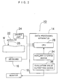
- a roughness measuring apparatus 10 of the embodiment shown in Fig. 1 is constituted by a measurement unit 12, a data processing apparatus 14, an input device (keyboard: measurement area specifying device) 16 and a monitor 18.
- the measurement unit 12 has a pickup 22 for measuring the surface roughness of a work W placed on a table 20, which is shown in Fig. 2, and this pickup 22 is supported by a holder 24A of a driving unit 24.
- the pickup 22 has a stylus 26 in its tip, and displacement of this stylus 26 is transformed into voltage through a differential transformer transducer (not shown) included in the driving unit 24. Then, this voltage value is subjected to A/D conversion by an A/D converter, and is outputted to a CPU (measurement data obtaining device, maximum value obtaining device) 28 of the data processing apparatus 14. Thereby, measurement data showing the surface roughness of the work W is obtained by a CPU 16.
- the driving unit 24 is mounted on a column 30 placed straight on the table 20 as in Fig. 1, and a motor is driven in accordance with instructions from the CPU 28 in Fig. 2, whereby the entire driving unit 24 is moved up and down along the column 30, and the holder 24A is moved from side to side. Furthermore, the driving unit 24 may also be operated by a joy stick 32 placed in the front face of the table 20.
- the data processing apparatus 14 as shown in Fig. 2 includes an auxiliary storage device 34 such as an EEPROM, which is a hard disk or a read only memory enabling electrical erase and write.
- an auxiliary storage device 34 such as an EEPROM, which is a hard disk or a read only memory enabling electrical erase and write.
- cutoff values defined in standards (0.08, 0.25, 0.8, 2.5 (mm)) are stored in this auxiliary storage device 34, and these cutoff values are read by the CPU 28.
- the CPU 28 uses a filter having the plurality of cutoff values to calculate a plurality of temporary evaluation values for each evaluation length corresponding to the plurality of cutoff values from the measurement data, and obtains a maximum value from these temporary evaluation values.
- the CPU 28 controls an evaluation value outputting device 36 to have this maximum value outputted to the monitor 18, with the maximum value determined as an effective evaluation value of the roughness of the measurement area in the cutoff value with the calculated maximum value falling within its roughness range.
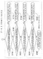
- parameters to be evaluated are first selected (S100). Furthermore, if a plurality of parameters is selected, a parameter that is most frequently used is generally given a higher priority to have the effective evaluation value of the parameter outputted first. In ISO, for example, they are prioritized in the order of Ra ⁇ Rz ⁇ RSm.
- the keyboard 16 is used to set the measurement length (measurement area) is at 12.5 mm (S110).
- the evaluation length is set to be a length five times as large as the sampling length (cutoff value), which is defined in ISO 4288.
- the measurement length is not limited to 12.5 mm, and may be changed according to estimated roughness.
- the parameter to be evaluated is calculated at the cutoff value of 0.08 mm as shown in Fig. 3.
- This parameter value is defined as P008.
- the maximum parameter value (SAmax in Fig. 4) is obtained out of 31 parameter values calculated for each of 31 evaluation ranges (temporary evaluation value: SA1, SA2, SA3 ... in Fig. 4) (S120).
- the parameter to be evaluated is calculated at the cutoff value of 0.25 mm.
- This parameter value is defined as P025. Since 10 evaluation ranges can be taken at this time, the maximum parameter value (SBmax in Fig. 4) is obtained out of 10 parameter values calculated for each of 10 evaluation ranges (temporary evaluation value: SB1, SB2, SB3 ... in Fig. 4) (S130).
- the parameter to be evaluated is calculated at the cutoff value of 0.8 mm. This parameter value is defined as P080. Since 3 evaluation ranges can be taken at this time, the maximum parameter value is obtained out of 3 parameter values calculated for each of 3 evaluation ranges (temporary evaluation value) (S140).
- the parameter to be evaluated is calculated at the cutoff value of 2.5 mm. This parameter value is defined as P250. Since 1 evaluation range can be taken at this time, the parameter value (temporary estimation value) is obtained as the maximum value (S150).
- a plurality of temporary evaluation values (3 values) can be obtained, and the reliability of the temporary evaluation value is thus improved.
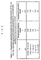
- the maximum value of P025 falls within the roughness ranges of Tables 1 to 3 (0.02 ⁇ Ra ⁇ 0.1, 0.1 ⁇ Rz, Rz1max ⁇ 0.5, 0.04 ⁇ RSm ⁇ 0.13) (S180), and if this maximum value falls within the range, the maximum value is outputted as an effective evaluation value of the measurement area, with the cutoff value defined as 0.25 mm (S190).
- the maximum value of P080 falls within the roughness ranges of Tables 1 to 3 (0.1 ⁇ Ra ⁇ 2, 0.5 ⁇ Rz, Rz1max ⁇ 10, 0.13 ⁇ RSm ⁇ 0.4) (S200), and if this maximum value falls within the range, the maximum value is outputted as an effective evaluation value of the measurement area, with the cutoff value defined as 0.8 mm (S210).
- 0.8 mm that is the most general value is set to be a cutoff value (S240).
- a plurality of temporary evaluation values for each evaluation length corresponding to the plurality of cutoff values is calculated from measurement data, and the maximum value is obtained from these temporary evaluation values. Then, this maximum value is outputted as an effective evaluation value of roughness of the measurement area, in the cutoff value with this maximum value falling within its roughness range.
- the effective evaluation is determined from a plurality of temporary evaluation values, the reliability of the effective evaluation value is high compared to conventional techniques in which the effective evaluation value is determined with one evaluation value, thus making it possible to measure the surface roughness of the work accurately.
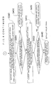
- the maximum values of parameter values (temporary evaluation values) of P008, P025, P080 and P250 are calculated in advance, and thereafter the effective evaluation value is determined from these four maximum values, but as shown in the flowchart of Fig. 8, the maximum value of parameter values (temporary evaluation values) may be calculated for each of P008, P025, P080 and P250 to determine the effective evaluation value.
- parameters to be evaluated are first selected (S300). Also in this case, as in the case of the measuring method in Fig. 3, if a plurality of parameters is selected, a parameter that is most frequently used is generally given a higher priority to have the effective evaluation value of the parameter outputted first.
- the evaluation length (measurement area) is set at 12.5 mm (S310). This measurement length can also be changed.
- the total range of the specified measurement length is measured to obtain measurement data showing the surface roughness of the work.
- the parameter to be evaluated is calculated at the cutoff value of 0.08 mm.
- This parameter value is defined as P008. Since 31 evaluation ranges can be taken at this time, the maximum parameter value is obtained out of 31 parameter values (temporary evaluation values) calculated for each of the 31 evaluation ranges (S320).
- the parameter to be evaluated is calculated at the cutoff value of 0.25 mm.
- This parameter value is defined as P025. Since 10 evaluation ranges can be taken at this time, the maximum parameter value is obtained out of 10 parameter values (temporary evaluation values) calculated for each of 10 evaluation ranges (S350).
- the parameter to be evaluated is calculated at the cutoff value of 0.8 mm. This parameter value is defined as P080. Since 3 evaluation ranges can be taken at this time, the maximum parameter value is obtained out of 3 parameter values (temporary evaluation values) calculated for each of 3 evaluation ranges (S380).
- the parameter to be evaluated is calculated at the cutoff value of 2.5 mm. This parameter value is defined as P250. Since one evaluation ranges can be taken at this time, the parameter value (temporary evaluation value) is obtained as the maximum value (S410).
- the roughness measuring method and roughness measuring apparatus since a plurality of temporary evaluation values for each evaluation length corresponding to a plurality of cutoff values is calculated from measurement data, and the maximum value is obtained out of these temporary evaluation values to determine the effective evaluation value, the reliability of the effective evaluation value is high compared to conventional techniques in which the effective evaluation value is determined with one evaluation value, thus making it possible to measure the surface roughness of a work accurately.
Landscapes
- Physics & Mathematics (AREA)
- General Physics & Mathematics (AREA)
- Length Measuring Devices With Unspecified Measuring Means (AREA)
- A Measuring Device Byusing Mechanical Method (AREA)
Abstract
Description
Claims (2)
- A roughness measuring method, comprising the steps of:specifying a measurement area of surface roughness of a work (W);measuring a total range of the specified measurement area to obtain measurement data showing the surface roughness of the work (W);using a filter having a plurality of predefined cutoff values to calculate a plurality of temporary evaluation values for each evaluation length corresponding to the plurality of cutoff values from the measurement data, thereby obtaining a maximum value of the plurality of temporary evaluation values;obtaining the maximum value as an effective evaluation value if the maximum value falls within a roughness range of the cutoff value used at that time; andusing a different cutoff value to obtain an effective evaluation value if the maximum value does not fall within the roughness range of the cutoff value used at that time.
- A roughness measuring apparatus, comprising:a stylus (26) which comes into contact with a surface of a work (W);a measurement area specifying device (14) which specifies a measurement area of surface roughness of the work (W);a measurement data obtaining device (14) which moves the stylus (26) across a total range of the measurement area specified by the measurement area specifying device (14) to obtain measurement data showing the surface roughness of the work (W);a maximum value obtaining device (14) which uses a filter having a plurality of predefined cutoff values to calculate a plurality of temporary evaluation values for each evaluation length corresponding to the plurality of cutoff values from the measurement data obtained by the measurement data obtaining device (14), thereby obtaining a maximum value of the plurality of temporary evaluation values; andan evaluation value outputting device (14) which obtains the maximum value as an effective value if the maximum value obtained by the maximum value obtaining device falls within a roughness range of the cutoff value used at that time, and uses a different cutoff value to obtain and output an effective evaluation value if the maximum value does not fall within the roughness range of the cutoff value used at that time.
Applications Claiming Priority (2)
| Application Number | Priority Date | Filing Date | Title |
|---|---|---|---|
| JP2000299670A JP3525432B2 (en) | 2000-09-29 | 2000-09-29 | Roughness measuring method and roughness measuring device |
| JP2000299670 | 2000-09-29 |
Publications (2)
| Publication Number | Publication Date |
|---|---|
| EP1197727A2 true EP1197727A2 (en) | 2002-04-17 |
| EP1197727A3 EP1197727A3 (en) | 2008-01-02 |
Family
ID=18781446
Family Applications (1)
| Application Number | Title | Priority Date | Filing Date |
|---|---|---|---|
| EP01123184A Withdrawn EP1197727A3 (en) | 2000-09-29 | 2001-09-27 | Roughness measuring method and apparatus |
Country Status (3)
| Country | Link |
|---|---|
| US (1) | US6696697B2 (en) |
| EP (1) | EP1197727A3 (en) |
| JP (1) | JP3525432B2 (en) |
Cited By (1)
| Publication number | Priority date | Publication date | Assignee | Title |
|---|---|---|---|---|
| EP1717545A1 (en) * | 2005-04-28 | 2006-11-02 | Tokyo Seimitsu Co.,Ltd. | Surface roughness/contour profile measuring instrument |
Families Citing this family (11)
| Publication number | Priority date | Publication date | Assignee | Title |
|---|---|---|---|---|
| US7625607B1 (en) | 2003-07-22 | 2009-12-01 | Newpage Wisconsin System Inc. | Low glare, high print gloss printing paper |
| KR101091260B1 (en) | 2003-12-29 | 2011-12-07 | 주식회사 포스코 | Galing Plated Testing Device |
| JP4570437B2 (en) * | 2004-10-20 | 2010-10-27 | 株式会社東京精密 | Surface roughness / contour shape measuring device |
| US20090025464A1 (en) * | 2005-08-23 | 2009-01-29 | Masafumi Ishii | Surface-roughness/contour measuring apparatus |
| JP5312032B2 (en) | 2007-06-29 | 2013-10-09 | 株式会社東京精密 | Surface shape measuring apparatus and surface shape measuring method |
| JP4417986B2 (en) * | 2007-07-18 | 2010-02-17 | 株式会社ミツトヨ | Surface texture measuring device |
| JP6086311B2 (en) * | 2012-03-28 | 2017-03-01 | 日立金属株式会社 | Evaluation method of polishability of steel for mold and evaluation method of polishability of mold |
| DE102013015237A1 (en) * | 2013-09-13 | 2015-03-19 | Blum-Novotest Gmbh | Roughness measuring instrument for use in a machine tool and method for measuring roughness in a machine tool |
| CN105841657B (en) * | 2016-03-25 | 2018-05-18 | 北京科技大学 | A kind of edge effect suppressing method during metal surface pattern gaussian filtering |
| KR102180526B1 (en) * | 2019-08-16 | 2020-11-18 | 한양대학교 산학협력단 | Potable surface measurement device and controlling method thereof |
| CN118912278B (en) * | 2024-07-15 | 2025-11-11 | 湖南科技大学 | Portable installed pipeline with roughness adjustable and use method |
Family Cites Families (10)
| Publication number | Priority date | Publication date | Assignee | Title |
|---|---|---|---|---|
| LU86194A1 (en) * | 1985-12-05 | 1987-07-24 | Centre Rech Metallurgique | METHOD FOR THE CONTINUOUS MEASUREMENT OF THE ROUGHNESS OF THE SURFACE OF A COLD ROLLED PRODUCT |
| GB2242976A (en) * | 1990-04-12 | 1991-10-16 | Rank Taylor Hobson Ltd | Measuring surface characteristics |
| US5204826A (en) * | 1991-02-01 | 1993-04-20 | General Electric Company | Quality assurance of surface treatments by analysis of substrate surface line traces |
| US5204734A (en) * | 1991-06-12 | 1993-04-20 | Wyko Corporation | Rough surface profiler and method |
| GB2272059B (en) * | 1992-10-20 | 1996-03-20 | Mitutoyo Corp | Surface-roughness measuring apparatus |
| JPH08159751A (en) * | 1994-12-08 | 1996-06-21 | Nippon Sheet Glass Co Ltd | Method for evaluating surface of glass plate |
| JP3241615B2 (en) * | 1996-11-01 | 2001-12-25 | 株式会社東京精密 | Method and apparatus for automatically setting measurement conditions of surface roughness profile measuring machine |
| US5955654A (en) * | 1997-08-07 | 1999-09-21 | Vlsi Standards, Inc. | Calibration standard for microroughness measuring instruments |
| EP0915105B1 (en) * | 1997-11-07 | 2003-04-09 | Rohm And Haas Company | Plastic substrates for electronic display applications |
| US6132942A (en) * | 1998-10-30 | 2000-10-17 | Eastman Kodak Company | Imaging base with backside roughness at two frequencies |
-
2000
- 2000-09-29 JP JP2000299670A patent/JP3525432B2/en not_active Expired - Fee Related
-
2001
- 2001-09-21 US US09/956,952 patent/US6696697B2/en not_active Expired - Fee Related
- 2001-09-27 EP EP01123184A patent/EP1197727A3/en not_active Withdrawn
Cited By (1)
| Publication number | Priority date | Publication date | Assignee | Title |
|---|---|---|---|---|
| EP1717545A1 (en) * | 2005-04-28 | 2006-11-02 | Tokyo Seimitsu Co.,Ltd. | Surface roughness/contour profile measuring instrument |
Also Published As
| Publication number | Publication date |
|---|---|
| JP2002107144A (en) | 2002-04-10 |
| JP3525432B2 (en) | 2004-05-10 |
| US6696697B2 (en) | 2004-02-24 |
| EP1197727A3 (en) | 2008-01-02 |
| US20020038854A1 (en) | 2002-04-04 |
Similar Documents
| Publication | Publication Date | Title |
|---|---|---|
| EP1197727A2 (en) | Roughness measuring method and apparatus | |
| US7376261B2 (en) | Surface scan measuring device and method of forming compensation table for scanning probe | |
| EP0004757A1 (en) | Capacitive non-contact gauging system | |
| EP2128584A2 (en) | Pressure sensor calibration method | |
| US20030190069A1 (en) | Method of measuring a line edge roughness of micro objects in scanning microscopes | |
| GB2146150A (en) | Digital indication type measuring machine and measured data storage device thereof | |
| US20040200084A1 (en) | Filler gauge with flexible measurement | |
| CN115824048A (en) | Spectral confocal sensor calibration method, system, device and readable storage medium | |
| EP1203925B1 (en) | Roughness measuring method and apparatus | |
| JP2005083918A (en) | Instrument and method for measuring shape, analyzer and program for analyzing shape, and recording medium | |
| JPS62145125A (en) | Scanning radiation thermometer | |
| CN105928482B (en) | Shape measuring apparatus, machining apparatus, and shape measuring method | |
| JP7296279B2 (en) | Shape measuring device and detector calibration method | |
| JP5046296B2 (en) | Displacement sensor | |
| JPH0515542A (en) | Ultrasonic tomographic apparatus | |
| JP2006214801A (en) | System for analyzing surface roughness data | |
| JP2006064686A (en) | Electronic length / angle measuring instrument | |
| JP7362468B2 (en) | Machined surface shape prediction device and method | |
| JP2006284199A (en) | Residual stress measuring device and measuring method thereof | |
| JP2971026B2 (en) | Image processing apparatus and image processing method | |
| KR100743908B1 (en) | How to measure hole / plate spacing | |
| JP2025069038A (en) | Liquid sensor and detection method | |
| CN117425815A (en) | Specific gravity measuring device | |
| JPS62195535A (en) | Measuring method for yield point elongation | |
| JPS6148082B2 (en) |
Legal Events
| Date | Code | Title | Description |
|---|---|---|---|
| PUAI | Public reference made under article 153(3) epc to a published international application that has entered the european phase |
Free format text: ORIGINAL CODE: 0009012 |
|
| AK | Designated contracting states |
Kind code of ref document: A2 Designated state(s): AT BE CH CY DE DK ES FI FR GB GR IE IT LI LU MC NL PT SE TR |
|
| AX | Request for extension of the european patent |
Free format text: AL;LT;LV;MK;RO;SI |
|
| PUAL | Search report despatched |
Free format text: ORIGINAL CODE: 0009013 |
|
| AK | Designated contracting states |
Kind code of ref document: A3 Designated state(s): AT BE CH CY DE DK ES FI FR GB GR IE IT LI LU MC NL PT SE TR |
|
| AX | Request for extension of the european patent |
Extension state: AL LT LV MK RO SI |
|
| RIC1 | Information provided on ipc code assigned before grant |
Ipc: G01B 21/30 20060101ALI20071129BHEP Ipc: G01B 7/34 20060101AFI20011115BHEP |
|
| 17P | Request for examination filed |
Effective date: 20080303 |
|
| 17Q | First examination report despatched |
Effective date: 20080506 |
|
| AKX | Designation fees paid |
Designated state(s): DE GB |
|
| STAA | Information on the status of an ep patent application or granted ep patent |
Free format text: STATUS: THE APPLICATION IS DEEMED TO BE WITHDRAWN |
|
| 18D | Application deemed to be withdrawn |
Effective date: 20160401 |