EP1197376A2 - Pivot mechanism for a seat recliner - Google Patents
Pivot mechanism for a seat recliner Download PDFInfo
- Publication number
- EP1197376A2 EP1197376A2 EP01124036A EP01124036A EP1197376A2 EP 1197376 A2 EP1197376 A2 EP 1197376A2 EP 01124036 A EP01124036 A EP 01124036A EP 01124036 A EP01124036 A EP 01124036A EP 1197376 A2 EP1197376 A2 EP 1197376A2
- Authority
- EP
- European Patent Office
- Prior art keywords
- locking member
- pivot
- locking
- movement
- convex
- Prior art date
- Legal status (The legal status is an assumption and is not a legal conclusion. Google has not performed a legal analysis and makes no representation as to the accuracy of the status listed.)
- Withdrawn
Links
Images


Classifications
-
- B—PERFORMING OPERATIONS; TRANSPORTING
- B60—VEHICLES IN GENERAL
- B60N—SEATS SPECIALLY ADAPTED FOR VEHICLES; VEHICLE PASSENGER ACCOMMODATION NOT OTHERWISE PROVIDED FOR
- B60N2/00—Seats specially adapted for vehicles; Arrangement or mounting of seats in vehicles
- B60N2/24—Seats specially adapted for vehicles; Arrangement or mounting of seats in vehicles for particular purposes or particular vehicles
- B60N2/42—Seats specially adapted for vehicles; Arrangement or mounting of seats in vehicles for particular purposes or particular vehicles the seat constructed to protect the occupant from the effect of abnormal g-forces, e.g. crash or safety seats
- B60N2/433—Safety locks for back-rests, e.g. with locking bars activated by inertia
-
- B—PERFORMING OPERATIONS; TRANSPORTING
- B60—VEHICLES IN GENERAL
- B60N—SEATS SPECIALLY ADAPTED FOR VEHICLES; VEHICLE PASSENGER ACCOMMODATION NOT OTHERWISE PROVIDED FOR
- B60N2/00—Seats specially adapted for vehicles; Arrangement or mounting of seats in vehicles
- B60N2/02—Seats specially adapted for vehicles; Arrangement or mounting of seats in vehicles the seat or part thereof being movable, e.g. adjustable
- B60N2/20—Seats specially adapted for vehicles; Arrangement or mounting of seats in vehicles the seat or part thereof being movable, e.g. adjustable the back-rest being tiltable, e.g. to permit easy access
- B60N2/206—Seats specially adapted for vehicles; Arrangement or mounting of seats in vehicles the seat or part thereof being movable, e.g. adjustable the back-rest being tiltable, e.g. to permit easy access to a position in which it can be used as a support for objects, e.g. as a tray
-
- B—PERFORMING OPERATIONS; TRANSPORTING
- B60—VEHICLES IN GENERAL
- B60N—SEATS SPECIALLY ADAPTED FOR VEHICLES; VEHICLE PASSENGER ACCOMMODATION NOT OTHERWISE PROVIDED FOR
- B60N2/00—Seats specially adapted for vehicles; Arrangement or mounting of seats in vehicles
- B60N2/02—Seats specially adapted for vehicles; Arrangement or mounting of seats in vehicles the seat or part thereof being movable, e.g. adjustable
- B60N2/22—Seats specially adapted for vehicles; Arrangement or mounting of seats in vehicles the seat or part thereof being movable, e.g. adjustable the back-rest being adjustable
- B60N2/235—Seats specially adapted for vehicles; Arrangement or mounting of seats in vehicles the seat or part thereof being movable, e.g. adjustable the back-rest being adjustable by gear-pawl type mechanisms
- B60N2/2352—Seats specially adapted for vehicles; Arrangement or mounting of seats in vehicles the seat or part thereof being movable, e.g. adjustable the back-rest being adjustable by gear-pawl type mechanisms with external pawls
Landscapes
- Engineering & Computer Science (AREA)
- Aviation & Aerospace Engineering (AREA)
- Transportation (AREA)
- Mechanical Engineering (AREA)
- Chairs For Special Purposes, Such As Reclining Chairs (AREA)
- Seats For Vehicles (AREA)
Abstract
Description
- The present invention relates to a pivot mechanism and in particular, but not exclusively, to a pivot mechanism for use in a seat recliner mechanism. The invention also relates to a recliner mechanism and a vehicle seat including such a mechanism.
- Many vehicle seats include a tilting/tipping mechanism that allows the angle of the seat back to be adjusted. The seat back is generally attached to the seat base through a pivot mechanism that includes a locking mechanism for locking the seat back at the desired angle.
- In one such pivot mechanism, for example as described in DE-OS-2931873, the seat back is attached to a pivot arm that is provided with a set of ratchet teeth. Those teeth are engaged by a locking plate having a complementary set of teeth. The locking plate can be moved away from the pivot arm to disengage the two sets of teeth, allowing the angle of the seat back to be adjusted, and can the be moved back towards the pivot arm, to engage the teeth and lock the seat back in position.
- The pivot mechanism naturally has to be able to withstand a number of forces during normal use including in particular the rearwards force caused by a passenger leaning against the seat back. However, for safety and to comply with worldwide legislation, it also has to be able to withstand the much greater forces that might be generated if the vehicle is involved in a collision. In particular, if the seat back carries the upper anchoring point for the seat belt, a very large forwards force may be generated in the event of a frontal collision, owing to the inertia of the passenger. Such transient forces may be many times greater than the forces experienced during normal usage and the pivot mechanism must be able to withstand them without collapsing.
- The very large forces generated by a collision can cause plastic deformation of the pivot mechanism. For example, the pivot pin on which the pivot arm is mounted may be driven forwards, causing partial separation of the two sets of teeth forming the locking mechanism. The forces carried by the locking mechanism may then be concentrated on just one or two of the teeth, causing those teeth to fail, followed by sequential failure of all the remaining teeth as the load is transferred to them (the so-called "domino effect").
- It is an object of the present invention to provide a pivot mechanism that mitigates at least some of the disadvantages of prior art pivot mechanisms.
- According to one aspect of the present invention there is provided a pivot mechanism including a first element, a second element that is rotatably mounted on the first element via a pivot means, and a locking mechanism including a convex tooth segment provided on the second element and a locking member having a concave tooth segment, the locking member being mounted on the first element for movement between a locked position in which the convex and concave tooth segments are engaged preventing rotation of the second element and an unlocked position in which the tooth segments are disengaged; characterised in that the centre of curvature of the convex tooth segment is offset from the centre of curvature of the concave tooth segment whereby, in normal usage, the convex and concave tooth segments are only partially engaged when the locking member is in the locked position.
- Owing to the offset of the centres of curvature, the mechanism is able to absorb some plastic deformation without failing. The deformation has the effect of driving more of the teeth into engagement, thereby spreading the load between the tooth segments and increasing the strength of the locking mechanism.
- Advantageously, the point of engagement between the tooth segments is towards one end of the concave tooth segment, which in the case of a pivot mechanism for a vehicle seat is the rear end of the tooth segment. This gives the mechanism greater strength in one direction than the other, which is important in situations where the pivot mechanism is more likely to encounter very large loads in one direction than another, for example in a vehicle that is involved in a collision. In many countries, these load bearing characteristics are dictated by legislation. The off-centre location of the engagement point also serves to remove free play from the mechanism and compensates automatically for both tolerance and wear.
- The degree and direction of offset depends on the design criteria including the balance of the strength requirements for loads acting in different directions on the mechanism, and the dimensions and load-bearing characteristics of the other components of the mechanism.
- Advantageously, the effective radius of the concave tooth segment is larger than the effective radius of the convex tooth segment. The ratio of the effective radii may be in the range 1.0-1.3, preferably 1.1-1.2, more preferably approximately 1.15.
- Advantageously, the centres of curvature of the convex and concave tooth segments are located on a line that is substantially radial to both tooth segments, and said line intersects the concave tooth segment towards one end thereof, which in the case of a pivot mechanism for a vehicle seat is the rear end of the tooth segment.
- Advantageously, the pivot mechanism includes a cam element that engages the locking member and is constructed and arranged to control movement thereof between said locked and unlocked positions, said cam element including a first cam surface for driving the locking member towards the locked position and a second cam surface for driving the locking member towards the unlocked position.
- According to a further aspect of the invention there is provided a pivot mechanism including a first element, a second element that is rotatably mounted on the first element via a pivot means, and a locking mechanism including a convex tooth segment provided on the second element, a locking member having a concave tooth segment, the locking member being mounted on the first element for movement between a locked position in which the convex and concave tooth segments are engaged preventing rotation of the second element and an unlocked position in which the tooth segments are disengaged, and a cam element that engages the locking member and is constructed and arranged to control movement thereof between said locked and unlocked positions; characterised in that the cam element includes a first cam surface for driving the locking member towards the locked position and a second cam surface for driving the locking member towards the unlocked position.
- According to a further aspect of the invention there is provided a pivot mechanism including a first element, a second element that is rotatably mounted on the first element via a pivot means, a locking member having a first locking formation that complements a second locking formation provided on the second element, the locking member being mounted for movement between a locked position in which the first and second locking formations are engaged, so preventing rotation of the second element, and an unlocked position in which the locking formations are disengaged, at least one guide member for guiding movement of the locking member and a control member for controlling movement of the locking member; characterised in that when the locking member is in the locked position, the control member exerts on the locking member a force having a first component that acts in the direction of movement of the locking member and a second component acts perpendicular to said direction of movement.
- When the mechanism is locked, the locking member is urged against the second element by the control member. The force acting upon the locking member has a first component that acts in the direction of movement of the locking member, which locks the second element in position, and a second component that is perpendicular to the direction of movement of the locking member, which urges the locking member against the guide member (or one of the guide members). This removes chuck (free play) from the mechanism and compensates for wear of the components.
- Advantageously, the first and second locking formations engage one another at an engagement point P, which is offset from a line L that extends through the pivot axis of the pivot means in the direction of movement of the locking member.
- Advantageously, the control member includes a rotatable cam and the first and second locking formations engage one another at an engagement point P, which is offset from a line that extends through the pivot axis of the pivot means and the rotation axis of the cam.
- The pivot mechanism may have locking formations allowing the first and second elements to be locked in one or more positions.
- According to a further aspect of the invention there is provided a pivot mechanism including a first element, a second element that is rotatably mounted on the first element via pivot means, a locking member having a first locking formation that complements a second locking formation provided on the second element, the locking member being mounted for movement between a locked position in which the first and second locking formations are engaged, so preventing rotation of the second element, and an unlocked position in which the locking formations are disengaged, at least one guide member for guiding movement of the locking member and a control member for controlling movement of the locking member; characterised by a compensating element that urges the locking member against said at least one guide member to remove chuck from the mechanism.
- The wedge member removes chuck (free play) from the mechanism and compensates for wear of the components.
- Advantageously, the compensating element includes a wedge member that is urged into a gap adjacent the locking member. The wedge member may be urged into the gap by means of a spring.
- According to a further aspect of the invention there is provided a recliner mechanism for a vehicle seat having a seat base and a reclining seat back, said recliner mechanism including a pivot mechanism as described in one of the preceding statements of invention.
- The recliner mechanism may include a lock out mechanism for driving the locking member into engagement with the convex tooth segment in the event of a collision.
- According to a further aspect of the invention there is provided a recliner mechanism for a vehicle seat having a seat base and a reclining seat back, said recliner mechanism including a pivot mechanism that includes a pivot arm rotatably mounted on a base member via a pivot pin, and a locking mechanism including a convex tooth segment provided on the pivot arm, and a locking member having a concave tooth segment, the locking member being mounted on the base member for movement between a locked position in which the convex and concave tooth segments are engaged preventing rotation of the pivot arm and an unlocked position in which the tooth segments are disengaged; characterised by a lock out mechanism for driving the locking member into engagement with the convex tooth segment in the event of a collision.
- According to a further aspect of the invention there is provided a vehicle seat including a seat base and a reclining seat back that is attached to the seat base by means of a recliner mechanism according to the preceding statement of invention.
- Embodiments of the invention will now be described by way of example with reference to the accompanying drawings, in which:
- Figure 1 is an exploded isometric view of a first pivot mechanism according to the invention;
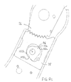
- Figure 2 is a sectional side view of the first pivot mechanism;
- Figures 3A and 3B are partial schematic side views of a prior art pivot mechanism, before and after deformation;
- Figure 4 is a partial schematic side views of the first pivot mechanism;
- Figures 5a and 5b are enlarged partial schematic side views of the first pivot mechanism, showing the mechanism before and after a collision causing plastic deformation of the mechanism;
- Figure 6a is a sectional front view at an enlarged scale, showing the pivot pin and sleeve of the first pivot mechanism;
- Figure 6b is a sectional front view showing the pivot pin of a modified pivot mechanism;
- Figure 7 is a sectional side view of a second pivot mechanism according to the invention;
- Figures 8a to 8e illustrate the cam and cam follower structure of a third pivot mechanism according to the invention;
- Figures 9 to 14 illustrate various forms of a lock out mechanism of a fourth pivot mechanism according to the invention;
- Figures 15 to 18 are sectional side views of a fifth pivot mechanism;
- Figures 19 to 22 are sectional side views of a sixth pivot mechanism;
- Figures 23 to 26 are sectional side views of a seventh pivot mechanism, and
- Figures 27 to 30 are sectional side views of an eighth pivot mechanism.
-
- A pivot mechanism according to the invention is shown generally in figures 1 and 2 of the drawings. The pivot mechanism is similar in most respects to the mechanism described in our British patent application No. 0104334.8, the content of which is incorporated by reference herein.
- Each reclining vehicle seat may include two such pivot mechanisms, which are interlinked and mounted on either side of the seat and join the reclining seat back to the seat base, preferably at the extremities (the widest point) of the seat. Alternatively, the seat may include a pivot mechanism as shown in the drawings on just one side and a plain pivot on the opposite side. In practice, the mechanism will normally be covered, either by the upholstery of the seat or by a rigid cover.
- The pivot mechanism includes a
housing 1 formed from two steel plates, those being aflat closing plate 2 and a pressed plate 4 that has a shallow U-shaped cross-section, comprising a substantially flat side plate 6 and front and rearperipheral walls flat closing plate 2. Theplates 2,4 are welded together along the free edges of theperipheral walls - The
housing 1 is roughly boot-shaped and is secured at its lower end (the sole of the "boot") to a mounting member 11 that is attached to one of the seat slides or to the seat base. Thehousing 1 is thus fixed relative to the seat base. Alternatively, thehousing 1 may be attached direct to the slide or seat base. Towards the upper end of the housing (at the knee of the "boot"), a gap is provided between the front and rearperipheral walls opening 12 into the housing. - A
pivot arm 14 made of steel plate, which in use is attached to and supports the seat back, extends through theopening 12 and is mounted via asleeve 15 on apivot pin 16 that extends through the housing and is located in corresponding openings 18 in theside plates 2,4. Thesleeve 15, which serves as a stress relief bush and is described in more detail below, may be omitted if not required. - One end of the
pivot pin 16 is welded or fixed to apin head 20, which is secured to theside plate 2 by areaction pin 22 to prevent rotation of the pivot pin. This mounting method avoids welding onto theside plate 2 and thus avoids compromising the material integrity of the plate, ensuring maximum housing strength. It also allows thepivot pin 16 to be demounted. - Pivoting movement of the
pivot arm 14 about thepin 16 is limited by engagement of the arm with the front and rearperipheral walls opening 12. Thus, rearwards or reclining movement is limited by the arm engaging afirst stop surface 24 on the rearperipheral wall 10, and forwards or tipping movement of the arm is limited by the arm engaging asecond stop surface 26 on the frontperipheral wall 8. - A clock spring (not shown) may be mounted on the second end of the
pivot pin 16 that extends outwards beyond thehousing 1. The spring is connected to thepivot arm 14 and biasses the seat back towards an upright position from a reclined position. - The
pivot arm 14 may be locked in a number of different reclined positions by means of a locking mechanism. A first set of teeth forming aconvex tooth segment 36 is provided at the lower end of thepivot arm 14. A lockingmember 38 comprising a metal plate having a second set of teeth forming aconcave tooth segment 40 is located below the pivot arm and mounted for up and down sliding movement within thehousing 1, between the rearperipheral wall 10 and aglide block 42, which is located between the lockingmember 38 and the frontperipheral wall 8. - The locking
member 38 has acentral opening 44 that serves as a cam follower arrangement. This opening encloses and is engaged by arotatable cam element 46. Thecam element 46 is mounted on asecond pivot pin 48 that extends through thehousing 1. - When the
cam element 46 is in the position shown in figure 2, theconcave tooth segment 40 on the lockingmember 38 is locked in engagement with theconvex tooth segment 36 provided at the lower end ofpivot arm 14, thereby preventing movement of the arm. To release the locking element, thecam element 46 is rotated from that position anticlockwise through an angle of approximately 90°. This draws the lockingmember 38 downwards so that theconcave tooth segment 40 disengages theconvex tooth segment 36 on thepivot arm 14. The seat back can then be rotated to a different angle. - The average segment tooth angle for the two sets of teeth preferably lies in the range 50 ° to 75°, and is preferably approximately 60°. If the angle is less than 50° the teeth may be too weak to withstand the stresses placed upon them, particularly in the event of a collision, whereas if the angle is greater than 75 ° the forces tending to push the sets of teeth apart when the mechanism is loaded may be too large to be contained by the housing.
- The front and rear
peripheral walls glide block 42 is wedge-shaped, having front and rear surfaces that converge upwards at the same small angle. The inner face of theglide block 42 is therefore parallel to the rearperipheral wall 10. This allows the lockingmember 38 to slide between those surfaces, movement of the lockingmember 38 being guided by the rearperipheral wall 10 and the rear surface of theglide block 42. - The
glide block 42 is capable of sliding movement relative to thehousing 1 and is biassed upwards by aleaf spring 52 that sits on the upper edge of the mounting member 11. This produces a wedging action, which ensures that there is no fore-and-aft chuck (free play) in the mechanism. The glide block thus serves as a compensating element that compensates automatically for wear of the components and prevents judder and rattle. - Fig. 3A of the drawings shows schematically the pivot mechanism described in our earlier British patent application No. 0104334.8. The radius of curvature Rarm of the
convex tooth segment 36 provided at the lower end of thepivot arm 14 is exactly matched to the radius of curvature Rlock of theconcave tooth segment 40 provided on the lockingmember 38, and both tooth forms have the same centre of curvature C. As a result, the two sets of teeth mesh perfectly, providing theoretically the highest possible load bearing capacity. - We have found that in the event of a frontal collision, the pivot mechanism can experience plastic deformation, owing to the very high transient forces transmitted through it from the inertial loading of a passenger secured to the seat back by a seat belt, or luggage stowed behind the seat back. Typically, as the mechanism is deformed, the holes 18 in the housing become elongated allowing the
pivot pin 16 to move forwards from itsoriginal position 16 to a new position 16' shown in broken lines. This causes thetooth segments rear edge 60 of the mechanism, as shown in Fig. 3B. - As a result of this deformation, the teeth towards the
rear edge 60 of the tooth segments may no longer fully engage each other. The entire load will therefore be borne by one or two teeth at thefront edge 62 of the tooth segments, rather than being spread evenly over the whole length of the two tooth segments. If that load is too great for the front teeth to bear, they will deform and fail. The load will then be transferred to the next teeth, which may also deform and fail, and this process may continue, leading to sequential failure of all the teeth and collapse of the entire locking mechanism. - In the present invention, this problem is avoided by using a modified tooth form, as shown in Fig. 4. In this modified tooth form, the radii of curvature of the two tooth segments are not matched, and the centres of curvature of the tooth segments are offset from one another.
- The curvature of a tooth segment may be defined in terms of its effective radius (R*), which is normally equal to the mean of the inner and outer tooth radii, measured from the centre of curvature C to the roots and the tips of the teeth: i.e.,
- In the example shown in Fig. 4, the effective radius of the
convex tooth segment 36 on thearm 14 is slightly less than the effective radius of theconcave tooth segment 40 on the locking member 38: i.e.,arm 14 and R*lock is the effective radius of the lockingmember 38. - Typical values for these radii are as follows:
- Arm: R'arm = 43.07mm, R"arm = 46.8mm, R*arm = 44.94mm
- Locking member: R"lock = 49.63mm, R'lock = 53.45mm, R*lock = 51.54mm
-
- In this case, the ratio of the effective radii (R*lock/R*arm) is equal to approximately 1.15. It will be appreciated however that the radii in any particular case will depend on the specified load bearing requirements and the dimensions and structure of the other components of the mechanism.
- To accommodate the different effective radii, the centres of curvature are offset, the centre of curvature Carm of the
convex tooth segment 36 being located closer to the teeth than the centre of curvature Clock of theconcave tooth segment 40. The radial separation of the two centres of curvature is equal to the difference between the effective radii, so that the teeth mesh correctly at one point, referred to herein as the "engagement point" P. - Preferably, in forward-facing set applications, the engagement point P is located in the rear half of the locking
member 38, between the centre of theconcave tooth segment 40 and itsrear edge 60. For example, as shown in Fig. 4a, the engagement point P may coincide with the second tooth from the rear edge of theconcave tooth segment 40. The centres of curvature of the arm Carm and the locking member Clock are therefore located on a radius Rp that intersects the tip of that tooth. - As shown more clearly in Fig. 5a, the two
segments front edge 62 of the lockingmember 38 than at therear edge 60. Nevertheless, the engagement between the two segments is sufficiently strong to withstand the forces and wear encountered during normal usage. - Should the vehicle be involved in a frontal collision, there may be some plastic deformation of the pivot mechanism, the result of which is shown in Fig. 5b. The pivot pin has been displaced forwards from its usual position and, as a result, the teeth towards the
front edge 62 of thepivot arm 40 have been brought into engagement with the corresponding teeth of the lockingmember 36, thereby increasing the number of teeth in contact. The forces are therefore shared between a increased number of teeth, so reducing the likelihood of the teeth failing. There has also been some deformation of the teeth around the original engagement point P, but this is not sufficiently serious to cause those teeth to fail. - The locking mechanism is therefore able to meet the specified load requirements more efficiently, and its strength increases with the severity of the crash. Testing has shown that the arrangement described above significantly increases the strength of the mechanism.
- The
sleeve 15 that surrounds thepivot pin 16 is shown in more detail in Fig. 6A. It extends through thehousing plates 2,4 and thepivot pin 16 and is designed to relieve stress around the openings 18 in the housing plates, thereby reducing plastic deformation and increasing the strength of the mechanism. Thesleeve 15 may however be omitted if not required, as shown in Fig. 6B - A second embodiment of the invention is shown in Fig. 7. In this embodiment, the wedge-shaped
glide block 42 is omitted and the lockingmember 38 is instead mounted for sliding movement between the frontperipheral wall 8 and the rearperipheral wall 10. - As in the previous example shown in Fig. 4, the effective radius of the
convex tooth segment 36 on thearm 14 is slightly less than the effective radius of theconcave tooth segment 40 on the lockingmember 38, and the centres of curvature are offset, the centre of curvature of the convex tooth segment being located closer to the teeth than the centre of curvature of the concave tooth segment. In this example, the engagement point P coincides with the second tooth from the rear edge of theconcave tooth segment 40. The twotooth segments member 38 than at the rear edge. - The locking
member 38 has acentral opening 44, which is engaged by arotatable cam element 46. When the cam element is in the "locked" position shown in Fig. 7, it exerts an upwards force on the locking member, which is transmitted through thepivot arm 14 to thepivot pin 16. That force is transmitted through the engagement point P, the direction of that force being shown by abroken line 70. The engagement point P does not lie on a straight line intersecting the axes of thepivot pin 16 and thecam element 46. Instead, the engagement point P is located in the rear half of the locking member, and theline 70 along which the compressive force is transmitted is therefore bent. The compressive force therefore generates a resultant force on the lockingmember 38 that presses it hard against the rearperipheral wall 10. - The effect of this resultant force is to remove any free play between the locking member and the
housing 1. The mechanism therefore compensates automatically for both tolerance and wear, without the need for the slidingwedge member 42 of the first embodiment shown in Figs. 1 and 2. - Various modifications of the invention are possible, some of which will now be described.
- Although it is preferred that the radii of curvature of the two tooth segments are not matched, and the centres of curvature of the tooth segments are offset from one another, it may be sufficient in certain circumstances just to offset the centres of curvature, for example by moving the pivot point backwards, while maintaining the same radii of curvature for both tooth segments. This will create a small gap between the two tooth segments at the front edge of the locking member, which will close when the mechanism suffers plastic deformation in a collision.
- Alternatively, the same effect may be achieved by using teeth of different sizes, so that they become fully engaged only when the mechanism is deformed owing to very high load forces.
- Instead of the symmetrical teeth shown in the drawings, the tooth segments may be provided with asymmetric (saw tooth) teeth, so that they can withstand a greater force in the forward direction without separation than in the rearwards direction. This increases the ability of the mechanism to survive a serious frontal collision without collapsing.
- In the mechanism shown in the accompanying drawings, the locking
member 38 is located in thehousing 1 that is attached to the seat base and thepivot arm 14 is attached to the seat back. It should however be understood that the mechanism may be inverted, so that thepivot arm 14 is attached to the seat base and thehousing 1 is attached to the seat back. Thepivot arm 14 will then remain stationary whilst thehousing 1 and the lockingmember 38 rotate with the seat back about the axis of thepivot pin 16. This arrangement may be preferred when, for example, a control handle for operating thecam element 48 is to be located at the top of the seat back rather than on the seat base. - Instead of a box section, the
housing 1 may for example comprise two flat plates joined together with rivets, a single plate or a frame to which the other components are attached, or a flattened tube. Thecam element 48 may be located in other positions, for example beneath the lockingmember 38. Instead of two guide members, a single guide member may be provided that controls movement of the locking member. Further, the mechanism may be made from different materials, including other metals and metal alloys, plastics materials and composite materials. - Although the pivot mechanism is particularly suited to use in a seat recliner mechanism, it is not restricted to that use. It may also be used in various other mechanisms and industries including, for example, work benches, cranes, gearboxes, nano-mechanisms, mechanism counting devices, clock and watch mechanisms, inertia locking systems, brake or clutch compensating mechanisms and any other ratchet applications where two centres try to move apart when subjected to a load.
- Figures 8a to 8e illustrate the cam and cam follower structure of a third pivot mechanism according to the invention. The locking
member 38 has acentral opening 144 that serves as a cam follower arrangement. This opening encloses and is engaged by arotatable cam element 146. Thecam element 146 is mounted on thesecond pivot pin 48 that extends through thehousing 1. - The shapes of the
cam element 146 and theopening 144 that forms the cam follower are more complicated than in the previous embodiment, and are illustrated best by the drawings. It should be noted that thecam element 146 includes first andsecond cam surfaces cam follower surfaces 152a, 152b of theopening 144. The first cam andcam follower surfaces - The movement of the
cam element 146 and the resulting movement of the lockingmember 38 is illustrated sequentially in Figs. 8a to 8e. In Fig. 8a, the upper parts of the first cam andcam follower surfaces member 38 upwards into a locked position against theconvex tooth segment 36 at the lower end of thepivot arm 14. In Fig. 8b, thecam element 146 has been rotated a few degrees in the clockwise direction, reducing the pressure of the lockingmember 38 against theconvex tooth segment 36. In each of Figs. 8c, 8d and 8e, thecam element 146 has been rotated a few more degrees in the clockwise direction, thereby disengaging the lockingmember 38 from theconvex tooth segment 36. It will be noted that in each of these positions, both the upper and the lower cam andcam follower surfaces 150a,b 152a,b are engaged and movement of the lockingmember 38 is therefore fully controlled, and there is no lost motion in the mechanism. - Figures 9 to 14 illustrate various forms of a lock out mechanism of a fourth pivot mechanism according to the invention. The lock out mechanism serves to increase the pressure of the locking
member 38 against theconvex tooth segment 36 in the event of a collision, to reduce the possibility of the mechanism disengaging. - Figs. 9 and 10 illustrate a first form of the lock out mechanism, which is activated by movement of the seat belt buckle. In this mechanism, the cam element (not shown) that controls movement of the locking
member 38 is connected through thesecond pivot pin 48 to anoperating arm 160. This arm is connected through ashort wire cable 162 to acarrier plate 163 that engages thesupport arm 164 of aseat belt buckle 166, which is attached to a seatbelt attachment point 168 on the side of thehousing 1. Thecarrier plate 163 is constructed and arranged to move with thesupport arm 164, without affecting either the arm or the seatbelt attachment point 168. Arelease handle 170 is also connected to thepivot pin 48 and may be operated manually to release the lockingmember 38. Thecable 162 is normally slack, to allow anti-clockwise rotation of theoperating arm 160 when therelease handle 170 is operated. - In the event of a frontal collision, the
buckle support arm 164 will normally rotate clockwise under the load resulting from the inertia of a passenger sitting in the seat from the original position shown in Fig. 9 to the rotated position shown in Fig. 10. This snatches thecable 162 tight, drawing theoperating arm 160 in a clockwise direction to the position shown in Fig. 10 and driving the lockingmember 38 against theconvex tooth segment 36 of thepivot arm 14, to reduce the possibility of the mechanism disengaging. - Figs. 11 and 12 illustrate an alternative form of the lock out mechanism, in which the
seat belt buckle 166 has awire support arm 164. Thecable 162 is attached to a modifiedcarrier plate 163 that engages arigid sheath 172 at the lower end of thebuckle support arm 164 without affecting either the arm or the seatbelt attachment point 168. Operation of the mechanism is the same as that of the first mechanism shown in Figs. 9 and 10. The positions of the various components of the lock out mechanism after a frontal collision has taken place and the mechanism has been actuated are illustrated in Fig. 12. - A further lock out mechanism that is actuated in the event of a rear collision is shown in Fig. 13. The lock out mechanism includes a
pendulum 180 having aheavy bob 182, which is connected through thesecond pivot pin 48 to the cam element (not shown) that controls movement of the lockingmember 38. The release handle 170 is also connected to thepivot pin 48, the release handle being shown in its engaged position in full lines and in its disengaged position in broken lines. - Normally, the
pendulum 180 is in the forward position shown in broken lines. However, in the event of a rear collision, the inertia of thebob 182 drives thependulum 180 rearwards to the position shown in full lines, thereby driving the lockingmember 38 upwards against theconvex tooth segment 36 and locking the mechanism. - The arrangement shown in Fig. 14 includes two recliner mechanisms arranged side-by-side, for example at opposite ends of a reclining seat back (not shown), and linked by a cranked connecting
bar 190. The connectingbar 190 operates in exactly the same way as thependulum 180 and, in the event of a rear collision, rotates rearwards from the position shown in broken lines to that shown in full lines, thereby driving the lockingmember 38 upwards against theconvex tooth segment 36 and locking thepivot arm 14 in its position. - The recliner mechanism may of course include both types of lock out mechanism, to provide a lock out function in the event of either a frontal or a rearwards collision.
- A fifth form of the pivot mechanism is shown in Figs. 15 to 18. The pivot mechanism includes a base member 201 (the "first element") comprising a metal housing, and a pivot arm 202 (the "second element") that is rotatably mounted on the base member via pivot means 203. A locking
member 204 has afirst locking formation 205 that complements asecond locking formation 206 provided on thepivot arm 202, the first locking formation comprising a tooth-like element that engages a similarly-shaped notch in the pivot arm. The two side faces of the tooth and the corresponding side faces of the notch are inclined towards one another to produce a jamming effect as the tooth enters the notch, which prevents chuck between those parts. - The locking
member 204 is mounted on thebase member 201 between guide members 207,208 comprising the peripheral walls of the housing and is arranged for movement between a locked position (Fig. 15) in which the first and second locking formations are engaged, so preventing rotation of thepivot arm 202, and an unlocked position (Fig. 16) in which the locking formations are disengaged. Acontrol member 209 comprising a rotatable cam is provided in the housing for controlling movement of the locking member. - When the locking
member 204 is in the locked position (Fig. 15), the locking member is urged against thepivot arm 202 by thecontrol member 209. The first and second locking formations engage one another at an engagement point P, which is equidistant between the front and rear faces of the first locking element. This engagement point P is located towards therear guide member 207 and, in particular, is offset from a line L that extends through the pivot axis of the pivot means 203 in the direction of movement of the locking member. The engagement point P is also offset from a line that extends through the axes of the pivot means and the control member. - Owing to the offset position of the engagement point P, the force F acting upon the locking member has a first component F1 that acts in the direction of movement of the locking member, which locks the pivot arm in position, and a second component F2 that is transverse to the direction of movement of the locking member, which urges the locking member towards the
rear guide member 207. This removes chuck (free play) from the mechanism and compensates for wear of the components. - The
pivot arm 202 may be rotated to an alternative position (Fig. 17) and locked in that position (Fig. 18) by the engagement of secondary locking formations 210,211 on thepivot arm 202 and the lockingmember 204. It will be understood that additional alternative locking positions may also be provided. - As indicated above, the
base member 201 includes a metal housing, which is formed from two steel plates, those being a flat closing plate and a pressed plate that has a shallow U-shaped cross-section. The raised edges of the pressed plate form the front and rear guide members 208,207. In this example, the two plates are joined together by means of a set of tabs 215 on the edges of the flat plate that engage corresponding openings in the pressed plate. These fixing tabs may of course be replaced by any other suitable fixing method, such as welding. - It should be understood that the structure of the pivot mechanism may be inverted. This is illustrated in Figs. 19 to 22 in which the pivot arm 301 (the "first element") comprises a metal housing and is rotatably mounted on the fixed base member 302 (the "second element") via a pivot means 303. A locking
member 304 has afirst locking formation 305 that complements asecond locking formation 306 provided on thebase member 302. The lockingmember 304 is mounted on thepivot arm 301 between guide members 307,308 for movement between a locked position (Fig. 19) in which the first and second locking formations are engaged preventing rotation of thepivot arm 301 and an unlocked position (Fig. 20) in which the locking formations are disengaged. Acontrol member 309 is provided for controlling movement of the locking member. - When the locking
member 304 is in the locked position (Fig. 19), the locking member is urged against the base member by thecontrol member 309. The first and second locking formations engage one another at an engagement point P, which is offset from a line L that extends through the pivot axis of the pivot means 303 in the direction of movement of the locking member. Owing to the offset position of the engagement point P, the force F acting upon the locking member has a first component F1 that acts in the direction of movement of the locking member, which locks the pivot arm in position, and a second component F2 that is transverse to the direction of movement of the locking member, which urges the locking member towards therear guide member 307. This removes chuck (free play) from the mechanism and compensates for wear of the components. - The
pivot arm 301 may be rotated to an alternative position (Fig. 21) and locked in that position (Fig. 22) by the engagement of secondary locking formations 310,311 on thebase member 302 and the lockingmember 304. - A sixth embodiment of the invention is shown in Figs. 23 to 26. The pivot mechanism includes a base member 401 (the "first element"), and a pivot arm 402 (the "second element") that is rotatably mounted on the base member via a pivot means 403. A locking
member 404 has afirst locking formation 405 that complements asecond locking formation 406 provided on thepivot arm 402. The lockingmember 404 is mounted on thebase member 401 402 between guide members 407,408 for movement between a locked position (Fig. 23) in which the first and second locking formations are engaged, so preventing rotation of thepivot arm 402, and an unlocked position (Fig. 24) in which the locking formations are disengaged. Acontrol member 409 comprising a cam is provided for controlling movement of the locking member. - The front edge of the locking member is spaced from the
front guide member 408 and set at a small acute angle to that guide member, leaving a wedge-shaped gap. A compensating element in the form of awedge member 412 is urged into the gap between the lockingmember 404 and theguide member 408 by aspring 413. Thewedge member 412 removes chuck from the mechanism and compensates for wear of the components. - The
pivot arm 402 may be rotated to an alternative position (Fig. 25) and locked in that position (Fig. 26) by the engagement of secondary locking formations 410,411 on thepivot arm 402 and the lockingmember 404. - It should be understood that the structure of the sixth pivot mechanism may also be inverted. This is illustrated in Figs. 27 to 30 in which the
pivot arm 501 comprises a metal housing and is rotatably mounted on thebase member 502 via a pivot means 503. A lockingmember 504 has afirst locking formation 505 that complements asecond locking formation 506 provided on thebase member 502. The lockingmember 504 is mounted on thepivot arm 501 between guide members 507,508 for movement between a locked position (Fig. 27) in which the first and second locking formations are engaged, so preventing rotation of thepivot arm 501, and an unlocked position (Fig. 28) in which the locking formations are disengaged. Acontrol member 509 is provided for controlling movement of the locking member. - The front edge of the locking member is spaced from the front guide member and set at a small acute angle to that guide member, leaving a wedge-shaped gap. A compensating element in the form of a
wedge member 512 is urged into the gap by aspring 513. Thewedge member 512 removes chuck and compensates for wear of the components. - The
pivot arm 501 may be rotated to an alternative position (Fig. 29) and locked in that position (Fig. 30) by the engagement of secondary locking formations 510,511 on thebase member 502 and the lockingmember 504.
Claims (15)
- A pivot mechanism including a first element, a second element that is rotatably mounted on the first element via a pivot means, and a locking mechanism including a convex tooth segment provided on the second element and a locking member having a concave tooth segment, the locking member being mounted for movement between a locked position in which the convex and concave tooth segments are engaged, so preventing rotation of the second element and an unlocked position in which the tooth segments are disengaged, wherein the centre of curvature of the convex tooth segment is offset from the centre of curvature of the concave tooth segment whereby, in normal usage, the convex and concave tooth segments are only partially engaged when the locking member is in the locked position.
- A pivot mechanism according to claim 1, in which the point of engagement between the tooth segments is towards one end of the concave tooth segment.
- A pivot mechanism according to claim 1, in which the effective radius of the concave tooth segment is larger than the effective radius of the convex tooth segment.
- A pivot mechanism according to claim 3, in which the ratio of the effective radii is in the range 1.0-1.3, preferably 1.1-1.2, more preferably approximately 1.15.
- A pivot mechanism according to claim 1, in which the centres of curvature of the convex and concave tooth segments are located on a line that is substantially radial to both tooth segments, and said line intersects the concave tooth segment towards one end thereof.
- A pivot mechanism according to claim 1, including a cam element that engages the locking member and is constructed and arranged to control movement thereof between said locked and unlocked positions, said cam element including a first cam surface for driving the locking member towards the locked position and a second cam surface for driving the locking member towards the unlocked position.
- A pivot mechanism including a first element, a second element that is rotatably mounted on the first element via a pivot means, and a locking mechanism including a convex tooth segment provided on the second element, a locking member having a concave tooth segment, the locking member being mounted for movement between a locked position in which the convex and concave tooth segments are engaged preventing rotation of the second element and an unlocked position in which the tooth segments are disengaged, and a cam element that engages the locking member and is constructed and arranged to control movement thereof between said locked and unlocked positions, wherein the cam element includes a first cam surface for driving the locking member towards the locked position and a second cam surface for driving the locking member towards the unlocked position.
- A pivot mechanism including a first element, a second element that is rotatably mounted on the first element via a pivot means, a locking member having a first locking formation that complements a second locking formation provided on the second element, the locking member being mounted for movement between a locked position in which the first and second locking formations are engaged, so preventing rotation of the second element, and an unlocked position in which the locking formations are disengaged, at least one guide member for guiding movement of the locking member and a control member for controlling movement of the locking member, the mechanism being constructed and arranged such that when the locking member is in the locked position, the control member exerts on the locking member a force having a first component that acts in the direction of movement of the locking member and a second component acts perpendicular to said direction of movement.
- A pivot mechanism according to claim 8, in which the first and second locking formations engage one another at an engagement point P, which is offset from a line L that extends through the pivot axis of the pivot means in the direction of movement of the locking member.
- A pivot mechanism according to claim 8, in which the control member includes a rotatable cam and the first and second locking formations engage one another at an engagement point P, which is offset from a line that extends through the pivot axis of the pivot means and the rotation axis of the cam.
- A pivot mechanism including a first element, a second element that is rotatably mounted on the first element via a pivot means, a locking member having a first locking formation that complements a second locking formation provided on the second element, the locking member being mounted for movement between a locked position in which the first and second locking formations are engaged, so preventing rotation of the second element, and an unlocked position in which the locking formations are disengaged, at least one guide member for guiding movement of the locking member and a control member for controlling movement of the locking member, including a compensating element that urges the locking member against said at least one guide member to remove chuck from the mechanism.
- A pivot mechanism according to claim 11, in which the compensating element includes a wedge member that is urged into a gap adjacent the locking member.
- A pivot mechanism according to claim 12, in which the wedge member is urged into the gap by means of a spring.
- A recliner mechanism for a vehicle seat having a seat base and a reclining seat back, said recliner mechanism including a pivot mechanism that includes a pivot arm rotatably mounted on a base member via a pivot pin, and a locking mechanism including a convex tooth segment provided on the pivot arm, and a locking member having a concave tooth segment, the locking member being mounted on the base member for movement between a locked position in which the convex and concave tooth segments are engaged preventing rotation of the pivot arm and an unlocked position in which the tooth segments are disengaged, including a lock out mechanism for driving the locking member into engagement with the convex tooth segment in the event of a collision.
- A vehicle seat including a seat base and a reclining seat back that is attached to the seat base by means of a recliner mechanism according to claim 14.
Applications Claiming Priority (10)
| Application Number | Priority Date | Filing Date | Title |
|---|---|---|---|
| GB0025020A GB0025020D0 (en) | 2000-10-12 | 2000-10-12 | Recliner mechanism for cars and other vehicles |
| GB0025020 | 2000-10-12 | ||
| GB0101007A GB0101007D0 (en) | 2000-10-12 | 2001-01-15 | Seat recliner mechanism |
| GB0101007 | 2001-01-15 | ||
| GB0108825A GB0108825D0 (en) | 2001-04-09 | 2001-04-09 | Pivot mechanism |
| GB0108825 | 2001-04-09 | ||
| GB0112547 | 2001-05-24 | ||
| GB0112547A GB0112547D0 (en) | 2000-10-12 | 2001-05-24 | Pivot mechanism |
| GB0122892 | 2001-09-24 | ||
| GB0122892A GB0122892D0 (en) | 2001-09-24 | 2001-09-24 | Pivot mechanism |
Publications (2)
| Publication Number | Publication Date |
|---|---|
| EP1197376A2 true EP1197376A2 (en) | 2002-04-17 |
| EP1197376A3 EP1197376A3 (en) | 2006-01-04 |
Family
ID=27515983
Family Applications (1)
| Application Number | Title | Priority Date | Filing Date |
|---|---|---|---|
| EP01124036A Withdrawn EP1197376A3 (en) | 2000-10-12 | 2001-10-09 | Pivot mechanism for a seat recliner |
Country Status (2)
| Country | Link |
|---|---|
| US (2) | US6869144B2 (en) |
| EP (1) | EP1197376A3 (en) |
Cited By (3)
| Publication number | Priority date | Publication date | Assignee | Title |
|---|---|---|---|---|
| GB2436121A (en) * | 2006-03-16 | 2007-09-19 | Atl Engineering | Seat reclining means with sliding ratchet lock |
| DE10330347B4 (en) * | 2003-07-05 | 2007-12-13 | Keiper Gmbh & Co.Kg | Fitting for a vehicle seat |
| DE10158309C5 (en) * | 2001-11-28 | 2012-06-28 | Keiper Gmbh & Co. Kg | Locking device for a vehicle seat |
Families Citing this family (19)
| Publication number | Priority date | Publication date | Assignee | Title |
|---|---|---|---|---|
| DE10123800B4 (en) * | 2001-05-16 | 2005-01-20 | Faurecia Autositze Gmbh & Co. Kg | Tilt adjustment for parts of motor vehicle seats, z. B. backrests |
| DE10312114A1 (en) * | 2003-03-19 | 2004-10-07 | Johnson Controls Gmbh | Adjustable locking device |
| FR2883523B1 (en) * | 2005-03-24 | 2007-06-15 | Faurecia Sieges Automobile | MECHANISM FOR ADJUSTING THE INCLINATION OF A SEAT OF A MOTOR VEHICLE |
| DE202005011386U1 (en) * | 2005-07-20 | 2005-09-29 | Kintec-Solution Gmbh | Mounting for adjustable back rest on e.g. seat comprises plate attached to seat frame and connected by pivot to plate on back rest which has catch with teeth cooperating with teeth on upper plate to hold back rest in different positions |
| DE102007030427B4 (en) * | 2006-12-28 | 2016-08-04 | Johnson Controls Gmbh | Backrest tilt adjuster and rear seat assembly |
| DE102007037138B4 (en) | 2007-03-16 | 2014-04-10 | Johnson Controls Gmbh | Actuating device, in particular for a vehicle seat |
| US8567865B2 (en) * | 2007-06-01 | 2013-10-29 | Toyota Boshoku Kabushiki Kaisha | Connecting apparatuses |
| CN101411593B (en) * | 2007-10-18 | 2011-07-27 | 厦门灿坤实业股份有限公司 | Frying and roasting equipment |
| US7878593B2 (en) * | 2008-06-23 | 2011-02-01 | Lear Corporation | Anti back drive device for a seat recliner |
| US8146998B2 (en) * | 2008-09-30 | 2012-04-03 | Lear Corporation | Chuck reducing device |
| CN102781719B (en) * | 2010-01-29 | 2016-01-20 | 江森自控科技公司 | Angle regulating mechanism |
| CN201814188U (en) * | 2010-06-30 | 2011-05-04 | 梁华春 | Three-gear welding hinge |
| CN201718842U (en) * | 2010-06-30 | 2011-01-26 | 梁华春 | Second hinge |
| GB2483056B (en) * | 2010-08-20 | 2012-12-12 | Gerard Crofts | A reclining mechanism for an item of furniture |
| JP5872853B2 (en) * | 2011-11-08 | 2016-03-01 | シロキ工業株式会社 | Reclining device |
| US8661619B2 (en) * | 2012-01-11 | 2014-03-04 | Dongguan Weihong Hardware And Plastic Products Co., Ltd. | Hinge adjuster |
| TWI492028B (en) * | 2012-12-18 | 2015-07-11 | Hon Hai Prec Ind Co Ltd | Rotating mechanism and electrical device |
| RU2674602C1 (en) * | 2018-05-16 | 2018-12-12 | Михаил Евгеньевич Сидоров | Seat backrest tilt angle adjustment mechanism |
| DE102018220029A1 (en) * | 2018-11-22 | 2020-05-28 | Lear Corporation | Seat back adjustment system |
Citations (2)
| Publication number | Priority date | Publication date | Assignee | Title |
|---|---|---|---|---|
| GB1043348A (en) | 1962-07-06 | 1966-09-21 | Basf Ag | Vat dyes comprising azo groupings and their production |
| DE2931873A1 (en) | 1979-08-06 | 1981-02-26 | Keiper Automobiltechnik Gmbh | Hinged fitment for adjustable seat backrest - is used in vehicle and consists of locking slide piece with cogged segment, concentric with pivot axle |
Family Cites Families (45)
| Publication number | Priority date | Publication date | Assignee | Title |
|---|---|---|---|---|
| DE2139357A1 (en) | 1971-08-06 | 1973-02-15 | Keiper Fa F | ARTICULATED FITTING FOR SEATS WITH ADJUSTABLE BACKREST, IN PARTICULAR FOR VEHICLE SEATS |
| GB1362877A (en) | 1971-11-26 | 1974-08-07 | Ford Motor Co | Seat recline mechanism |
| JPS4928467A (en) | 1972-07-14 | 1974-03-13 | ||
| DE2404598C3 (en) * | 1974-01-31 | 1979-04-12 | Metallwerk Max Brose Gmbh & Co, 8630 Coburg | Articulated fitting for vehicle seats |
| DE2552787C3 (en) | 1975-11-25 | 1979-10-25 | Keiper Automobiltechnik Gmbh & Co Kg, 5630 Remscheid | Articulated fittings for seats, in particular vehicle seats |
| ZA771889B (en) | 1976-05-28 | 1978-02-22 | Brugger Metalcraft | Seat adjusting mechanisms |
| JPS5551310Y2 (en) | 1976-11-01 | 1980-11-29 | ||
| GB1588867A (en) | 1977-08-05 | 1981-04-29 | Turner Ltd H | Seat reclining mechanism |
| DE8003679U1 (en) | 1980-02-12 | 1980-05-08 | C. Rob. Hammerstein Gmbh, 5650 Solingen | JOINT FITTING |
| DE121452T1 (en) | 1983-03-01 | 1985-04-11 | Tubauto, Levallois-Perret | SEAT-BACK JOINT FOR VEHICLES. |
| US4875735A (en) | 1984-03-30 | 1989-10-24 | Moyer George A | Seatback recliner mechanism |
| US4872726A (en) | 1984-09-19 | 1989-10-10 | Keiper Recaro Incorporated | Ratchet seat recliner with remote release |
| WO1986005958A1 (en) | 1985-04-12 | 1986-10-23 | Fuji Kiko Kabushiki Kaisha | Seat reclining structure |
| US4634182A (en) | 1985-08-09 | 1987-01-06 | P.L. Porter Co. | Seatback recliner mechanism and inertia operated lock |
| FR2594022B1 (en) | 1986-02-07 | 1988-05-27 | Cousin Cie Ets A & M Freres | ARTICULATION FOR COMPOSITE GRAIN SEAT BACK. |
| US4736986A (en) | 1986-10-08 | 1988-04-12 | Ikeda Bussan Co., Ltd. | Seat recliner assembly |
| CA1293681C (en) | 1988-12-28 | 1991-12-31 | George Croft | Adjustable latching device with memory feature for vehicle seat assemblies |
| US5224759A (en) | 1989-08-31 | 1993-07-06 | Fuji Kiko Co., Ltd. | Double lock recliner for automotive seat |
| US5205609A (en) | 1991-02-05 | 1993-04-27 | Bertrand Faure Ltd. | Eccentric gear backlash take-up mechanism for seat latches |
| US5154476A (en) | 1991-02-21 | 1992-10-13 | Hoover Universal, Inc. | Locking seat recliner |
| US5138744A (en) | 1991-03-13 | 1992-08-18 | Bertrand Faure Ltd. | Zero chuck recliner with floating pawl |
| EP0509865B1 (en) | 1991-03-29 | 1997-01-08 | Fujikiko Kabushiki Kaisha | Emergency lock mechanism for vehicular seat |
| JPH04371103A (en) | 1991-06-19 | 1992-12-24 | Toyota Autom Loom Works Ltd | Reclining adjuster |
| JP3021968B2 (en) * | 1992-06-05 | 2000-03-15 | アラコ株式会社 | Vehicle seat with reclining mechanism |
| CA2064490C (en) | 1992-03-31 | 1996-01-23 | Daniel Hughes | Spring biased inertial latch for vehicle seat assemblies |
| US5328241A (en) | 1993-06-07 | 1994-07-12 | Hoover Universal, Inc. | Seat recliner pawl with abbreviated teeth |
| JPH0769114A (en) | 1993-09-03 | 1995-03-14 | Ikeda Bussan Co Ltd | Emergency lock device for vehicle seat |
| US5433507A (en) * | 1993-10-06 | 1995-07-18 | Chang; Chung L. | Seatback recliner mechanism |
| JP2858450B2 (en) | 1993-12-27 | 1999-02-17 | トヨタ車体株式会社 | Reclining mechanism for vehicle seat |
| CA2161068C (en) | 1994-10-21 | 2007-04-24 | David L. Robinson | Seat recliner for reducing chucking |
| US5702156A (en) | 1995-02-17 | 1997-12-30 | Tachi-S Co., Ltd. | Reclining device |
| JP3080136B2 (en) | 1995-07-31 | 2000-08-21 | 池田物産株式会社 | Internal tooth type reclining device |
| DE19604672C1 (en) | 1996-02-09 | 1997-09-25 | Keiper Recaro Gmbh Co | Locking fitting for vehicle seats |
| US5749625A (en) | 1996-03-28 | 1998-05-12 | Fisher Dynamics Corporation | Seat recliner for reducing chucking |
| US5664836A (en) * | 1996-03-29 | 1997-09-09 | Tachi-S Co., Ltd. | Reclining device for vehicle seat |
| US5882080A (en) | 1996-09-26 | 1999-03-16 | Excel Industries, Inc. | Bi-directional inertial latch |
| US5733008A (en) | 1996-12-09 | 1998-03-31 | Atoma International, Inc. | Safety lock for non-linear recliner mechanism |
| DE19654395C1 (en) | 1996-12-27 | 1998-02-12 | Faure Bertrand Sitztech Gmbh | Cam for releasable locking of vehicle seat |
| US5788330A (en) | 1997-03-27 | 1998-08-04 | Fisher Dynamics Corporation | Seat hinge mechanism with easy entry memory feature |
| JP3968825B2 (en) | 1997-07-04 | 2007-08-29 | トヨタ紡織株式会社 | Reclining mechanism |
| JP3287454B2 (en) * | 1997-08-22 | 2002-06-04 | ジョンソン コントロールズ オートモーティブ システムズ株式会社 | Reclining device on both sides |
| US6209955B1 (en) | 1998-10-21 | 2001-04-03 | Johnson Controls Technology Company | Vehicle seat with a yielding recliner stop |
| DE19859239C1 (en) | 1998-12-22 | 2000-07-06 | Faure Bertrand Sitztech Gmbh | Inclination adjustment fitting for part area of road vehicle seat, such as back rest, has first and second parts connected with first and second part areas respectively |
| US6139104A (en) | 1999-01-29 | 2000-10-31 | Johnson Controls Technology Company | Multiple function seat back adjusting mechanism |
| US6139105A (en) | 1999-04-06 | 2000-10-31 | Dura Automotive Systems, Inc. | Easy entry latch for seat recliner |
-
2001
- 2001-10-09 US US09/974,253 patent/US6869144B2/en not_active Expired - Fee Related
- 2001-10-09 EP EP01124036A patent/EP1197376A3/en not_active Withdrawn
-
2003
- 2003-04-03 US US10/406,525 patent/US6796612B2/en not_active Expired - Fee Related
Patent Citations (2)
| Publication number | Priority date | Publication date | Assignee | Title |
|---|---|---|---|---|
| GB1043348A (en) | 1962-07-06 | 1966-09-21 | Basf Ag | Vat dyes comprising azo groupings and their production |
| DE2931873A1 (en) | 1979-08-06 | 1981-02-26 | Keiper Automobiltechnik Gmbh | Hinged fitment for adjustable seat backrest - is used in vehicle and consists of locking slide piece with cogged segment, concentric with pivot axle |
Cited By (4)
| Publication number | Priority date | Publication date | Assignee | Title |
|---|---|---|---|---|
| DE10158309C5 (en) * | 2001-11-28 | 2012-06-28 | Keiper Gmbh & Co. Kg | Locking device for a vehicle seat |
| DE10330347B4 (en) * | 2003-07-05 | 2007-12-13 | Keiper Gmbh & Co.Kg | Fitting for a vehicle seat |
| GB2436121A (en) * | 2006-03-16 | 2007-09-19 | Atl Engineering | Seat reclining means with sliding ratchet lock |
| WO2007104906A1 (en) | 2006-03-16 | 2007-09-20 | Atl Engineering (Uk) Limited | Recliner mechanism |
Also Published As
| Publication number | Publication date |
|---|---|
| US6869144B2 (en) | 2005-03-22 |
| US20020057008A1 (en) | 2002-05-16 |
| EP1197376A3 (en) | 2006-01-04 |
| US6796612B2 (en) | 2004-09-28 |
| US20030189372A1 (en) | 2003-10-09 |
Similar Documents
| Publication | Publication Date | Title |
|---|---|---|
| US6796612B2 (en) | Pivot mechanism | |
| KR100513576B1 (en) | Round type recliner for vehicles | |
| US6209955B1 (en) | Vehicle seat with a yielding recliner stop | |
| US5749624A (en) | Seat reclining device | |
| EP1225086B1 (en) | Reclining device for a seat | |
| EP1405756B1 (en) | Seat recliner for vehicle | |
| US8602498B2 (en) | Seat reclining apparatus | |
| EP1279553A2 (en) | Seat reclining device | |
| US7588294B2 (en) | Seat reclining device for vehicle | |
| EP1260405A1 (en) | Seat recliner | |
| US20010001220A1 (en) | Pivot mechanism for a vehicle seat and seat fitted with said mechanism | |
| EP1246734B1 (en) | A recliner mechanism | |
| US20080122281A1 (en) | Adjusting Mechanism and Vehicle Seat | |
| EP0888925B1 (en) | Reclining mechanism for vehicle seat | |
| US6644746B2 (en) | Seat integrated latch recliner assembly with inertial locking mechanism | |
| US7784872B2 (en) | Recliner mechanism | |
| US6161657A (en) | Mechanical lock with a cam-driven locking pawl | |
| US7021714B2 (en) | Recliner adjuster for a seat | |
| US20020067062A1 (en) | Pivot mechanism | |
| EP1036717A2 (en) | Lockbar with compensation for frame deformation | |
| CA2130497C (en) | Infinitely adjustable track locking mechanism | |
| JP5366282B2 (en) | Vehicle seat slide structure and vehicle seat having the structure | |
| US20020043853A1 (en) | Pivot mechanism | |
| JP2004357799A (en) | Seat reclining device for vehicle | |
| KR200313604Y1 (en) | Round type recliner for vehicles |
Legal Events
| Date | Code | Title | Description |
|---|---|---|---|
| PUAI | Public reference made under article 153(3) epc to a published international application that has entered the european phase |
Free format text: ORIGINAL CODE: 0009012 |
|
| AK | Designated contracting states |
Kind code of ref document: A2 Designated state(s): AT BE CH CY DE DK ES FI FR GB GR IE IT LI LU MC NL PT SE TR |
|
| AX | Request for extension of the european patent |
Free format text: AL;LT;LV;MK;RO;SI |
|
| PUAL | Search report despatched |
Free format text: ORIGINAL CODE: 0009013 |
|
| AK | Designated contracting states |
Kind code of ref document: A3 Designated state(s): AT BE CH CY DE DK ES FI FR GB GR IE IT LI LU MC NL PT SE TR |
|
| AX | Request for extension of the european patent |
Extension state: AL LT LV MK RO SI |
|
| 17P | Request for examination filed |
Effective date: 20060704 |
|
| AKX | Designation fees paid |
Designated state(s): AT BE CH CY DE DK ES FI FR GB GR IE IT LI LU MC NL PT SE TR |
|
| 17Q | First examination report despatched |
Effective date: 20070125 |
|
| STAA | Information on the status of an ep patent application or granted ep patent |
Free format text: STATUS: THE APPLICATION IS DEEMED TO BE WITHDRAWN |
|
| 18D | Application deemed to be withdrawn |
Effective date: 20090505 |