EP1197262A2 - Method and apparatus for manufacturing microspheres - Google Patents
Method and apparatus for manufacturing microspheres Download PDFInfo
- Publication number
- EP1197262A2 EP1197262A2 EP01301870A EP01301870A EP1197262A2 EP 1197262 A2 EP1197262 A2 EP 1197262A2 EP 01301870 A EP01301870 A EP 01301870A EP 01301870 A EP01301870 A EP 01301870A EP 1197262 A2 EP1197262 A2 EP 1197262A2
- Authority
- EP
- European Patent Office
- Prior art keywords
- plate
- microspheres
- dispersed phase
- continuous phase
- phase
- Prior art date
- Legal status (The legal status is an assumption and is not a legal conclusion. Google has not performed a legal analysis and makes no representation as to the accuracy of the status listed.)
- Granted
Links
Images


Classifications
-
- B—PERFORMING OPERATIONS; TRANSPORTING
- B01—PHYSICAL OR CHEMICAL PROCESSES OR APPARATUS IN GENERAL
- B01J—CHEMICAL OR PHYSICAL PROCESSES, e.g. CATALYSIS OR COLLOID CHEMISTRY; THEIR RELEVANT APPARATUS
- B01J13/00—Colloid chemistry, e.g. the production of colloidal materials or their solutions, not otherwise provided for; Making microcapsules or microballoons
- B01J13/02—Making microcapsules or microballoons
- B01J13/04—Making microcapsules or microballoons by physical processes, e.g. drying, spraying
-
- B—PERFORMING OPERATIONS; TRANSPORTING
- B01—PHYSICAL OR CHEMICAL PROCESSES OR APPARATUS IN GENERAL
- B01F—MIXING, e.g. DISSOLVING, EMULSIFYING OR DISPERSING
- B01F23/00—Mixing according to the phases to be mixed, e.g. dispersing or emulsifying
- B01F23/40—Mixing liquids with liquids; Emulsifying
- B01F23/41—Emulsifying
-
- B—PERFORMING OPERATIONS; TRANSPORTING
- B01—PHYSICAL OR CHEMICAL PROCESSES OR APPARATUS IN GENERAL
- B01F—MIXING, e.g. DISSOLVING, EMULSIFYING OR DISPERSING
- B01F25/00—Flow mixers; Mixers for falling materials, e.g. solid particles
- B01F25/30—Injector mixers
- B01F25/31—Injector mixers in conduits or tubes through which the main component flows
- B01F25/314—Injector mixers in conduits or tubes through which the main component flows wherein additional components are introduced at the circumference of the conduit
- B01F25/3142—Injector mixers in conduits or tubes through which the main component flows wherein additional components are introduced at the circumference of the conduit the conduit having a plurality of openings in the axial direction or in the circumferential direction
- B01F25/31425—Injector mixers in conduits or tubes through which the main component flows wherein additional components are introduced at the circumference of the conduit the conduit having a plurality of openings in the axial direction or in the circumferential direction with a plurality of perforations in the axial and circumferential direction covering the whole surface
-
- B—PERFORMING OPERATIONS; TRANSPORTING
- B01—PHYSICAL OR CHEMICAL PROCESSES OR APPARATUS IN GENERAL
- B01F—MIXING, e.g. DISSOLVING, EMULSIFYING OR DISPERSING
- B01F33/00—Other mixers; Mixing plants; Combinations of mixers
- B01F33/30—Micromixers
Definitions
- the present invention relates to a method and an apparatus for manufacturing emulsions for use in food, drugs, cosmetics or the like, emulsions for DDSs (Drug Delivery Systems), and microspheres (fine particles) which are solid fine particles or liquid fine particles used as a microcapsule, an ion exchange resin, a chromatography carrier or the like.
- DDSs Drug Delivery Systems
- microspheres fine particles which are solid fine particles or liquid fine particles used as a microcapsule, an ion exchange resin, a chromatography carrier or the like.
- a biphasic system for which a separated state is thermodynamically stable, is formed, such as that composed of a water phase and an organic phase which are emulsified to obtain a semi-stable emulsion, are conventionally known.
- particle sizes become 1,000 ⁇ m or more and are distributed over a wide range so that homogenous emulsions cannot be obtained.
- FIGS. 8 and 9 show a vertical sectional view of this apparatus.
- FIG. 9 shows a perspective view wherein a base and a plate are shown taken apart.
- a supply port 102 for a continuous phase a supply port 103 for a dispersed phase, and a withdrawal port 104 for emulsions are formed in a body 101 supported by a case 100.
- a bulkhead member 106 provided between the body 101 and a base 105 separates the supply port 103 for a dispersed phase from the withdrawal port 104 for emulsions.
- an opening 107 for a dispersed phase is formed in the center part of the base 105 and a gap is formed between the base 105 and a plate 108 placed opposite the base 105.
- the dispersed phase and the continuous phase are separated in a boundary section 109 formed in the base 105 and the dispersed phase and the continuous phase are mixed in a microchannel 110 formed in the boundary section 109.
- the dispersed phase supplied to the inside of the bulkhead member 106 through the supply port 103 enters a gap between the plate 108 and the base 105 through the opening 107.
- the dispersed phase enters the continuous phase through the microchannel 110, and thereby emulsions are formed.
- Spray drying method may be of three types, i.e., a centrifugal nozzle method, a pressure nozzle method and a two-fluid nozzle method.
- a turbulent flow is formed by rotating a nozzle at high speed or making a liquid flow at high speed, and the liquid is caused to form microspheres (fine particles) through a shear stress caused by the turbulent flow.
- a granulation apparatus As an apparatus for manufacturing microspheres, there is also known a granulation apparatus. Granulation apparatuses of many types are known, for example: a pumping type, a centrifugal flow type, a fluidized bed type, an air current type, a stirring type or the like. However, in methods employing each of these types of granulation apparatus, microspheres (liquid drops) are formed through a shear stress caused by a turbulent flow.
- a penetrating hole of a porous membrane or a nozzle from which microspheres are pumped has a circular shape or a nearly circular shape with respect to the opening shape.
- the opening shape of the portion from which the dispersed phase is pumped into the continuous phase is circular or nearly circular, since the force of a vertical direction uniformly acts on the boundary surface of the dispersed phase which is pumped from the opening, the dispersed phase is difficult to separate from the opening. Therefore, in the conventional arts, as mentioned above, a turbulent flow is formed, the dispersed phase is forced to separate from the opening through a shear stress caused by the turbulent flow, and thereby fine particles are produced.
- microspheres fine particles
- the dispersed phase is difficult to separate from the opening as liquid drops as mentioned above, the problem arises wherein the particle diameters of the manufactured microspheres are not uniform.
- a method for manufacturing microspheres comprising the steps of separating a dispersed phase and a continuous phase by a bulkhead in which at least one penetrating hole is formed, applying higher pressure to the dispersed phase than the continuous phase, and thereby pumping the dispersed phase through the at least one penetrating hole into the continuous phase, wherein a non-uniform shear stress is made to act toward the boundary surface of the dispersed phase which is pumped into the continuous phase through the at least one penetrating hole, so that microspheres are formed.
- the dispersed phase When the non-uniform shear stress acts toward the boundary surface of the dispersed phase which is pumped into the continuous phase through the penetrating hole, the dispersed phase is easy to separate and form into microspheres, so that microspheres having a uniform particle diameter can be manufactured.
- liquid is used as a dispersed phase and a continuous phase.
- liquid is used as a dispersed phase and air is used as a continuous phase.
- the amount of microspheres produced can be controlled by the supply pressure driving the dispersed phase.
- the supply pressure driving the dispersed phase at which the amount of microspheres produced is maximized in the range of stably producing microspheres is detected, and the operation is conducted at such pressure.
- the continuous phase In order to stably produce microspheres, it is required to move and supply the continuous phase existing around the boundary surface to the boundary surface at the time of shearing the boundary surface. Therefore, it is necessary that the continuous phase exist around the boundary surface at a certain amount. Also, the continuous phase needs to be supplied so as to withdraw produced microspheres.
- the ratio of a dispersed phase in emulsions can be optionally determined by varying the flow velocity of the continuous phase. Therefore, the optimum flow velocity of the continuous phase which satisfies the above-mentioned conditions is detected, and the operation is conducted at such flow velocity.
- the continuous phase By flowing the continuous phase at a predetermined velocity, not only the continuous phase can be supplied to the boundary surface, but also microspheres can be promoted to separate from the exit by supplying the continuous phase with mechanical force, such as ultrasonic or the like, which is applied to the continuous phase.
- mechanical force such as ultrasonic or the like
- Such external force has an effect not on shearing of liquid drops but of promoting separation after production (shearing).
- a first plate, an intermediate plate and a second plate are provided apart from each other in a case.
- a first flow path, from which liquid cannot escape and through which a dispersed phase flows, is provided between the first plate and the intermediate plate.
- a second flow path, from which liquid cannot escape and through which a continuous phase and a phase containing microspheres flow, is provided between the intermediate plate and the second plate.
- At least one penetrating hole which connects the first flow path and the second flow path is formed in the intermediate plate.
- the at least penetrating hole has a non-circular shape which results in non-uniform shear stress acting toward the boundary surface of the dispersed phase which is pumped therethrough into the continuous phase.
- a number of units each of which comprises the first plate, the intermediate plate and the second plate may be piled up, and thereby high productivity can be achieved.
- the opening shape of the penetrating hole formed in the intermediate plate may be a slot shape or a shape in which slots are combined. However, it is not limited to these shapes.
- etching treatment irradiation of electron rays
- a precision processing technique such as a CVD method or the like
- a high-density plasma etching treatment which is one among dry etching treatments.
- the first plate or the second plate transparent, it is possible to monitor the condition of producing microspheres from outside the apparatus with a CCD camera or the like.
- the apparatus for manufacturing microspheres according to the present invention comprises an annular case 1 in which plural plates and spacers are installed.
- the case 1 comprises the lower body 1a and the upper body 1b.
- a seal ring 3 a first plate 4 which is comprised of a transparent plate such as a glass plate or a plastic plate, an annular spacer 5 which is comprised of an elastic body, an intermediate plate 6 which is comprised of a silicon substrate or the like, an annular spacer 7, a second plate 8 and a seal ring 9 are inserted in this order into a concave portion 2 formed in the lower body 1a.
- the upper body 1b is superposed thereon. Further, the upper body 1b is attached to the lower body 1a with bolts or the like.
- a first flow path 11 from which liquid cannot escape is formed by the annular spacer 5 between the first plate 4 and the intermediate plate 6, and a dispersed phase flows therethrough.
- a second flow path 12 from which liquid cannot escape is formed by the annular spacer 7 between the second plate 8 and the intermediate plate 6, and a continuous phase and emulsions flow therethrough.
- a number of penetrating holes 13 are provided at the substantial center of the intermediate plate 6. These penetrating holes 13 are formed, for example, by a plasma etching treatment using excited fluorine compound gas as reactive gas.
- the opening portion of each penetrating hole has a slot shape of 9.5 ⁇ m in width (T1) and 23.6 ⁇ m in length (T2).
- T1 9.5 ⁇ m in width
- T2 23.6 ⁇ m in length
- the size of the penetrating hole 13 is not limited to these values and may be optionally determined.
- the shape of the opening portion of the penetrating hole is not a perfect square or circle.
- an L-shape, a T-shape, a cross shape, an H-shape or a shape formed by inserting a wire into a cylinder is preferable.
- openings 14 are formed at opposite corners of the intermediate plate 6. Openings 15 and 16 are respectively formed in the annular spacer 7 and the second plate 8, as shown in FIG.1, to coincide with the openings 14. Flow paths for introducing a dispersed phase are formed by the openings 14, 15 and 16. In the present apparatus, one of the two flow paths for introducing a dispersed phase is blocked with a stopper 17.
- openings 18 and 19 are formed in the second plate 8.
- the opening 18 is used as a flow path for introducing a continuous phase and the opening 19 is used as a flow path for withdrawing emulsions.
- a reservoir for a dispersed phase 21 is connected to the opening 16 by a pipe 20 and a pump P1.
- a reservoir for a continuous phase 23 is connected to the opening 18 by a pipe 22 and a pump P2.
- a reservoir for emulsions 25 is connected to the opening 19 by a pipe 24 and a pump P3.
- Each pipe is connected to each opening via a joint (not shown) so that liquid cannot escape.
- the second plate 8 comprises two plate materials 8a and 8b.
- a window portion is formed at the center of the plate materials 8a and 8b.
- a transparent plate 8c comprised of a glass plate or a plastic plate is supported with a seal in the window portion.
- no opening is formed in the intermediate plate 6 and the second plate 8.
- a flow path 31 for introducing (withdrawing) a dispersed phase a flow path 32 for introducing (withdrawing) a continuous phase and a flow path 33 for withdrawing (supplying) emulsions are formed in the case 1.
- the dispersed phase within the reservoir 21 is supplied to the first flow path 11 through the pump P1 and the pipe 20 at a predetermined pressure, and at the same time, the continuous phase within the reservoir 23 is supplied to the second flow path 12 through the pump P2 and the pipe 22 at a predetermined pressure.
- the dispersed phase within the first flow path 11 passes through the penetrating holes 13 of the intermediated plate 6 and is dispersed as microspheres into the continuous phase, so that emulsions are formed.
- the emlusions are withdrawn to the reservoir 25 through the pipe 24 and the pump P3.
- the shape of the penetrating hole 13 is not a square or circular shape. Therefore, when the dispersed phase is pumped from the penetrating hole, the force, which is perpendicular to the boundary surface and acts in the direction from the outside to the inside, has a distribution in the magnitude thereof, so that the boundary surface between the continuous phase and the dispersed phase is unstable, the shear to the boundary surface is promoted, and thereby fine and homogenous microspheres can be produced.
- the production velocity of microspheres can be adjusted by controlling the flow velocity of the dispersed phase within the first flow path 11 or the flow velocity of the continuous phase within the second flow path 12.
- microspheres it is also possible to vary the type of microspheres to be manufactured depending on the intermediate plate (hydrophilic or hydrophobic). In a case where a hydrophilic plate is used, microspheres of an oil-in-water type (O/W) can be manufactured. On the other hand, in a case where a hydrophobic plate is used, microspheres of a water-in-oil type (W/O) can be manufactured.
- Soybean oil was used as a dispersed phase and water containing sodium dodecyl sulfate of 0.3 wt % was used as a continuous phase.
- the driving pressure was set at 0.90 kPa or 1.80 kPa.
- the flow rate of the continuous phase was adjusted at 10ml/h. Applying these conditions, the production of microspheres was attempted.
- the dispersed phase When the driving pressure was at 0.90 kPa, the dispersed phase could not be pumped into the continuous phase, and thereby microspheres could not be manufactured. However, when the driving pressure was increased to 1.80 kPa, the dispersed phase could be pumped into the continuous phase through the penetrating holes.
- Microspheres manufactured in such a case were homogenous, having an extremely uniform particle diameter. It turned out that the reason is as follows:
- the cross-sectional shape of the penetrating hole is a slot shape
- the boundary surface between the dispersed phase and the continuous phase which exists at the surface of the membrane is deformed due to the cross-sectional shape of the penetrating hole.
- the deformation causes a distribution in the strength of the force which is perpendicular to the boundary surface and acts in the direction from the outside to the inside, so that the condition of the boundary surface is made unstable and the shear to the boundary surface is promoted.
- penetrating type microchannels having the cross-sectional shape which contributes to the deformation of the boundary surface are effective in manufacturing microspheres having a uniform size.
- the manufactured microspheres have the same size and the same distribution in the size even if the driving pressure is varied to 12 kPa and the flow rate of the continuous phase is varied to 200 ml/h.
- the maximum velocity of manufacturing microspheres is around 100 pieces/second per each microchannel. This corresponds to microspheres being manufactured at a high velocity of 125 ml/h maximum per a base assembly.
- the penetrating type microchannel having a circular cross-sectional shape in a case of using another penetrating type microchannel having a circular cross-sectional shape, the condition of the boundary surface between the dispersed phase and the continuous phase which exists at the surface of the membrane is stable and the shear to the boundary surface is difficult to promote. As a result, microspheres of a large size are manufactured.
- the penetrating type microchannel having a circular cross-sectional shape is inferior to the penetrating type microchannel having a slot-like cross-sectional shape in the size distribution of microspheres obtained thereby, and it is greatly influenced by the flow rate of the continuous phase. However, it can produce a high rate of output of emulsions compared to the conventional apparatus.
- microspheres according to the present invention is not limited to the production of emulsions. It can be utilized for many purposes. Hereinafter, some examples will be given.
- high-grade silicate of soda is uniformly dispersed into toluene containing a surface-active agent. Gelation is caused by injecting carbonic acid gas into the dispersed liquid (emulsions), and thereafter, solid and liquid are separated. The solid portion (fine particles) is immersed in hydrochloric acid, dehydrated after cleaning with distilled water, dried at 180°C, fired at 550 °C, and the surface-active agent is removed therefrom. Next, it is again immersed in hydrochloric acid and cleaned with water, and thereby high-grade silica particles are obtained.
- ODS dimethyloctadecylmonochlorosilane
- the present invention can be applied to the manufacture of polymer toner, pigment, a conductive spacer, metallic paint, particles for cleaning the environment, a flame retardant, a catalyst, a heat-storage agent, an anti-bacterial agent, pheromone, edible oil, physiological activation substances, an enzyme, aluminum flakes, Micanite, fertilizer, a biodegradable microcapsule, and so on.
- a heating medium obtained by dispersing phase change substances into a microcapsule it is possible to carry a large amount of heat with a small amount of a heating medium due to high latent heat of the phase change substances.
- a microcapsule heating medium is a novel one. It is superior to ordinary liquid in the characteristics of heat transfer. The characteristics are effective in utilizing unused heat of a relatively low temperature such as heat discharged from an atomic power plant.
- a sheet or a film with a microcapsule It is also possible to make a sheet or a film with a microcapsule.
- perfume constituents are confined in a microcapsule of several ⁇ m and this is printed onto a substrate such as a phonecard or the like with an offset printing.
- the capsule is broken when its printing surface is rubbed, and thereby perfume is emanated.
- the present invention can be applied to the manufacture of such functional inks.
- the present invention may be applied to the encapsulation of medicine, an electrophoresis display, or the like.
- the pressurized dispersed phase is pumped into the continuous phase through penetrating holes having a non-circular shape such as a slot shape, a shape in which slots are combined, or the like, the particle diameters of the dispersed phase are not distributed over a wide range in a case where the diameter is large, and thereby homogenous microspheres can be obtained.
- microspheres According to the present invention, homogenous microspheres can be efficiently manufactured.
- the present invention is applied to the manufacture of mayonnaise, chocolate, margarine, fat spread, or the like, it is possible to obtain ones which are difficult to separate even after preservation over a long period of time and which is made to be superior in mouthfeel by the fine and uniformly dispersed phase particles.
Landscapes
- Chemical & Material Sciences (AREA)
- Chemical Kinetics & Catalysis (AREA)
- Organic Chemistry (AREA)
- Dispersion Chemistry (AREA)
- Manufacturing Of Micro-Capsules (AREA)
- Colloid Chemistry (AREA)
- Physical Or Chemical Processes And Apparatus (AREA)
- Feeding, Discharge, Calcimining, Fusing, And Gas-Generation Devices (AREA)
- Medical Preparation Storing Or Oral Administration Devices (AREA)
- Glanulating (AREA)
- Silicon Compounds (AREA)
Abstract
Description
- The present invention relates to a method and an apparatus for manufacturing emulsions for use in food, drugs, cosmetics or the like, emulsions for DDSs (Drug Delivery Systems), and microspheres (fine particles) which are solid fine particles or liquid fine particles used as a microcapsule, an ion exchange resin, a chromatography carrier or the like.
- Techniques in which a biphasic system, for which a separated state is thermodynamically stable, is formed, such as that composed of a water phase and an organic phase which are emulsified to obtain a semi-stable emulsion, are conventionally known.
- As general emulsification methods, there have been described in "Science of Emulsions" (Asakura-shoten, 1971), the methods of using a mixer, a colloid mill, a homogenizer, etc., and the method of dispersion with sound waves, which are all well known.
- The general methods mentioned above have a disadvantage in that the diameters of dispersed phase particles in a continuous phase are distributed over a wide range.
- Therefore, a method of using filtration by means of a membrane comprising polycarbonate (Biochemica et Biophysica Acta, 557 (1979), North Holland Biochemical Press); a method using repeated filtrations through a PTFE (polytetrafluoroethylene) membrane (Proceedings of the 26th Autumn Meeting of the Society of Chemical Engineers, Japan, 1993); and a method of manufacturing homogenous emulsions by transferring a dispersed phase into a continuous phase through a porous glass membrane having uniform pores (Japanese Patent Application Laid-Open No. 2-95433) have been proposed. In addition, as a method of manufacturing emulsions using a nozzle or a porous plate, a laminar-flow dripping method (KAGAKU KOOGAKU Vol. 21, No. 4, 1957) is also known.
- The method using filtration through a membrane comprising polycarbonate and the method using repeated filtrations through a PTFE membrane theoretically cannot manufacture emulsions comprising particles larger than the membrane pores and cannot separate particles smaller than the membrane pores. These methods are therefore especially unsuitable for producing emulsions comprising large particles.
- In the method using a porous glass membrane having uniform pores, when the average diameter of the membrane pores is small, particle diameters are distributed in a narrow range and thus homogenous emulsions can be obtained. When the average diameter of the membrane pores is increased, however, particle diameters become distributed over a wide range so that homogenous emulsions cannot be obtained.
- In addition, in the laminar-flow dripping method, particle sizes become 1,000 µm or more and are distributed over a wide range so that homogenous emulsions cannot be obtained.
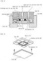
- Therefore, the inventors of the present invention formerly proposed an apparatus which can continuously produce homogenous emulsions in International Publication No. WO97/30783. The structure of this apparatus is shown in FIGS. 8 and 9. FIG. 8 is a vertical sectional view of this apparatus. FIG. 9 shows a perspective view wherein a base and a plate are shown taken apart. In this apparatus for producing emulsions, a supply port 102 for a continuous phase, a supply port 103 for a dispersed phase, and a
withdrawal port 104 for emulsions are formed in abody 101 supported by acase 100. Abulkhead member 106 provided between thebody 101 and abase 105 separates the supply port 103 for a dispersed phase from thewithdrawal port 104 for emulsions. In addition, anopening 107 for a dispersed phase is formed in the center part of thebase 105 and a gap is formed between thebase 105 and aplate 108 placed opposite thebase 105. The dispersed phase and the continuous phase are separated in aboundary section 109 formed in thebase 105 and the dispersed phase and the continuous phase are mixed in amicrochannel 110 formed in theboundary section 109. - The dispersed phase supplied to the inside of the
bulkhead member 106 through the supply port 103 enters a gap between theplate 108 and thebase 105 through theopening 107. The dispersed phase enters the continuous phase through themicrochannel 110, and thereby emulsions are formed. - As a prior art related to producing microspheres (fine particles) other than in emulsions, there is known a spray drying method. Spray drying method may be of three types, i.e., a centrifugal nozzle method, a pressure nozzle method and a two-fluid nozzle method. However, in each method, a turbulent flow is formed by rotating a nozzle at high speed or making a liquid flow at high speed, and the liquid is caused to form microspheres (fine particles) through a shear stress caused by the turbulent flow.
- As an apparatus for manufacturing microspheres, there is also known a granulation apparatus. Granulation apparatuses of many types are known, for example: a pumping type, a centrifugal flow type, a fluidized bed type, an air current type, a stirring type or the like. However, in methods employing each of these types of granulation apparatus, microspheres (liquid drops) are formed through a shear stress caused by a turbulent flow.
- In the conventional apparatus for producing emulsions, the spray dryer or the various granulation apparatuses as mentioned above, a penetrating hole of a porous membrane or a nozzle from which microspheres are pumped has a circular shape or a nearly circular shape with respect to the opening shape.
- In the case where the opening shape of the portion from which the dispersed phase is pumped into the continuous phase is circular or nearly circular, since the force of a vertical direction uniformly acts on the boundary surface of the dispersed phase which is pumped from the opening, the dispersed phase is difficult to separate from the opening. Therefore, in the conventional arts, as mentioned above, a turbulent flow is formed, the dispersed phase is forced to separate from the opening through a shear stress caused by the turbulent flow, and thereby fine particles are produced.
- However, in the case where microspheres (fine particles) are formed through a shear stress caused by the turbulent flow, since the dispersed phase is difficult to separate from the opening as liquid drops as mentioned above, the problem arises wherein the particle diameters of the manufactured microspheres are not uniform.
- In the prior art, as well as that relating to particle diameter, there is another problem that relates to production efficiency. For example, in the apparatus for producing emulsions shown in FIGS. 8 and 9, it is necessary to linearly form the microchannels on the periphery of the opening which is provided in the center part of the base. The number of microchannels per a base is at most 5000 in a case of small microchannels. The number is further decreased as the size of the microchannels is increased. Therefore, it is not easy to disperse homogenous particles of the dispersed phase into the continuous phase at high efficiency and as a result there is room for improvement with respect to the production cost.
- To solve the above-mentioned problems, according to the present invention, there is provided a method for manufacturing microspheres comprising the steps of separating a dispersed phase and a continuous phase by a bulkhead in which at least one penetrating hole is formed, applying higher pressure to the dispersed phase than the continuous phase, and thereby pumping the dispersed phase through the at least one penetrating hole into the continuous phase, wherein a non-uniform shear stress is made to act toward the boundary surface of the dispersed phase which is pumped into the continuous phase through the at least one penetrating hole, so that microspheres are formed.
- When the non-uniform shear stress acts toward the boundary surface of the dispersed phase which is pumped into the continuous phase through the penetrating hole, the dispersed phase is easy to separate and form into microspheres, so that microspheres having a uniform particle diameter can be manufactured.
- This can be achieved by making the cross-sectional shape of the penetrating hole a slot shape or the like which is not a perfect square or circle shape. By doing so, when the dispersed phase is pumped from the penetrating hole, the force, which is perpendicular to the boundary surface and acts in the direction from the outside to the inside, has a distribution in magnitude, so that the boundary surface between the continuous phase and the dispersed phase is unstable, the shear to the boundary surface is promoted, and thereby fine and homogenous microspheres can be produced.
- In a case directed to emulsions as microspheres, liquid is used as a dispersed phase and a continuous phase. In a case directed to spray drying, liquid is used as a dispersed phase and air is used as a continuous phase.
- Further, the amount of microspheres produced can be controlled by the supply pressure driving the dispersed phase. The supply pressure driving the dispersed phase at which the amount of microspheres produced is maximized in the range of stably producing microspheres is detected, and the operation is conducted at such pressure.
- In order to stably produce microspheres, it is required to move and supply the continuous phase existing around the boundary surface to the boundary surface at the time of shearing the boundary surface. Therefore, it is necessary that the continuous phase exist around the boundary surface at a certain amount. Also, the continuous phase needs to be supplied so as to withdraw produced microspheres. The ratio of a dispersed phase in emulsions can be optionally determined by varying the flow velocity of the continuous phase. Therefore, the optimum flow velocity of the continuous phase which satisfies the above-mentioned conditions is detected, and the operation is conducted at such flow velocity.
- By flowing the continuous phase at a predetermined velocity, not only the continuous phase can be supplied to the boundary surface, but also microspheres can be promoted to separate from the exit by supplying the continuous phase with mechanical force, such as ultrasonic or the like, which is applied to the continuous phase. Such external force has an effect not on shearing of liquid drops but of promoting separation after production (shearing).
- As an example of the present invention can be listed an apparatus for implementing the above-mentioned method for manufacturing microspheres. In this example, a first plate, an intermediate plate and a second plate are provided apart from each other in a case. A first flow path, from which liquid cannot escape and through which a dispersed phase flows, is provided between the first plate and the intermediate plate. A second flow path, from which liquid cannot escape and through which a continuous phase and a phase containing microspheres flow, is provided between the intermediate plate and the second plate. At least one penetrating hole which connects the first flow path and the second flow path is formed in the intermediate plate. The at least penetrating hole has a non-circular shape which results in non-uniform shear stress acting toward the boundary surface of the dispersed phase which is pumped therethrough into the continuous phase.
- With this structure, it is possible to greatly increase the number of the penetrating holes per an intermediate plate (for example, 1000/cm2 or more), and thereby mass-production of microspheres can be achieved.
- A number of units each of which comprises the first plate, the intermediate plate and the second plate may be piled up, and thereby high productivity can be achieved.
- The opening shape of the penetrating hole formed in the intermediate plate may be a slot shape or a shape in which slots are combined. However, it is not limited to these shapes.
- As a method for forming the penetrating hole in the intermediate plate, it is preferable to use an etching treatment, irradiation of electron rays, a precision processing technique such as a CVD method or the like, or a high-density plasma etching treatment which is one among dry etching treatments.
- Further, by making at least one part of the first plate or the second plate transparent, it is possible to monitor the condition of producing microspheres from outside the apparatus with a CCD camera or the like.
- Some preferred embodiments of the present invention will now be described by way of example, with reference to the following drawings:
- FIG. 1 is a sectional view of an apparatus for manufacturing microspheres according to the present invention;
- FIG. 2 is a plane view of an intermediate plate according to the present invention;
- FIG. 3 is a sectional view of an intermediate plate according to the present invention;
- FIG. 4 is an enlarged, cut-away perspective view of one part of an intermediate plate according to the present invention (before the production of microspheres);
- FIG. 5 is an enlarged cut-away perspective view of one part of an intermediate plate according to the present invention (showing the production of microspheres);
- FIGS. 6(a) - 6(e) show other embodiments of a penetrating hole according to the present invention;
- FIG. 7 is a sectional view of another embodiment of an apparatus for manufacturing microspheres according to the present invention;
- FIG. 8 is a sectional view of a conventional apparatus; and
- FIG. 9 is a perspective view showing the relationship between the base and the transparent plate used in the conventional apparatus.
-
- As shown in FIG. 1, the apparatus for manufacturing microspheres according to the present invention comprises an
annular case 1 in which plural plates and spacers are installed. - Specifically, the
case 1 comprises the lower body 1a and theupper body 1b. Aseal ring 3, afirst plate 4 which is comprised of a transparent plate such as a glass plate or a plastic plate, anannular spacer 5 which is comprised of an elastic body, anintermediate plate 6 which is comprised of a silicon substrate or the like, anannular spacer 7, asecond plate 8 and aseal ring 9 are inserted in this order into aconcave portion 2 formed in the lower body 1a. Theupper body 1b is superposed thereon. Further, theupper body 1b is attached to the lower body 1a with bolts or the like. - A
first flow path 11 from which liquid cannot escape is formed by theannular spacer 5 between thefirst plate 4 and theintermediate plate 6, and a dispersed phase flows therethrough. Asecond flow path 12 from which liquid cannot escape is formed by theannular spacer 7 between thesecond plate 8 and theintermediate plate 6, and a continuous phase and emulsions flow therethrough. - As shown in FIGS. 2 and 3, a number of penetrating
holes 13 are provided at the substantial center of theintermediate plate 6. These penetratingholes 13 are formed, for example, by a plasma etching treatment using excited fluorine compound gas as reactive gas. The opening portion of each penetrating hole has a slot shape of 9.5 µm in width (T1) and 23.6 µm in length (T2). However, the size of the penetratinghole 13 is not limited to these values and may be optionally determined. - In order to form fine and homogenous microspheres it is preferable that the shape of the opening portion of the penetrating hole is not a perfect square or circle. For example, as shown in FIGS. 6(a) - 6(e), an L-shape, a T-shape, a cross shape, an H-shape or a shape formed by inserting a wire into a cylinder is preferable.
- As shown in FIG. 2,
openings 14 are formed at opposite corners of theintermediate plate 6.Openings annular spacer 7 and thesecond plate 8, as shown in FIG.1, to coincide with theopenings 14. Flow paths for introducing a dispersed phase are formed by theopenings stopper 17. - Further,
other openings second plate 8. Theopening 18 is used as a flow path for introducing a continuous phase and theopening 19 is used as a flow path for withdrawing emulsions. - A reservoir for a dispersed
phase 21 is connected to theopening 16 by apipe 20 and a pump P1. A reservoir for acontinuous phase 23 is connected to theopening 18 by apipe 22 and a pump P2. A reservoir foremulsions 25 is connected to theopening 19 by apipe 24 and a pump P3. Each pipe is connected to each opening via a joint (not shown) so that liquid cannot escape. - The
second plate 8 comprises twoplate materials plate materials transparent plate 8c comprised of a glass plate or a plastic plate is supported with a seal in the window portion. With this structure, it is possible to monitor from outside whether or not microspheres are produced normally in thesecond flow path 12 by anoptical reading device 26 such as a CCD camera or the like. It is also possible to accurately control the production velocity of microspheres depending on variation in the driving pressure. - In another embodiment as shown in FIG. 7, no opening is formed in the
intermediate plate 6 and thesecond plate 8. Instead, aflow path 31 for introducing (withdrawing) a dispersed phase, aflow path 32 for introducing (withdrawing) a continuous phase and aflow path 33 for withdrawing (supplying) emulsions are formed in thecase 1. - For manufacturing microspheres with this apparatus, the dispersed phase within the
reservoir 21 is supplied to thefirst flow path 11 through the pump P1 and thepipe 20 at a predetermined pressure, and at the same time, the continuous phase within thereservoir 23 is supplied to thesecond flow path 12 through the pump P2 and thepipe 22 at a predetermined pressure. - Then, as shown in FIG. 5, the dispersed phase within the
first flow path 11 passes through the penetratingholes 13 of the intermediatedplate 6 and is dispersed as microspheres into the continuous phase, so that emulsions are formed. The emlusions are withdrawn to thereservoir 25 through thepipe 24 and the pump P3. - According to the present invention, the shape of the penetrating
hole 13 is not a square or circular shape. Therefore, when the dispersed phase is pumped from the penetrating hole, the force, which is perpendicular to the boundary surface and acts in the direction from the outside to the inside, has a distribution in the magnitude thereof, so that the boundary surface between the continuous phase and the dispersed phase is unstable, the shear to the boundary surface is promoted, and thereby fine and homogenous microspheres can be produced. - The production velocity of microspheres can be adjusted by controlling the flow velocity of the dispersed phase within the
first flow path 11 or the flow velocity of the continuous phase within thesecond flow path 12. - It is also possible to vary the type of microspheres to be manufactured depending on the intermediate plate (hydrophilic or hydrophobic). In a case where a hydrophilic plate is used, microspheres of an oil-in-water type (O/W) can be manufactured. On the other hand, in a case where a hydrophobic plate is used, microspheres of a water-in-oil type (W/O) can be manufactured.
- Hereinafter, an explanation of some embodiments will be given in detail.
- Soybean oil was used as a dispersed phase and water containing sodium dodecyl sulfate of 0.3 wt % was used as a continuous phase. The driving pressure was set at 0.90 kPa or 1.80 kPa. The flow rate of the continuous phase was adjusted at 10ml/h. Applying these conditions, the production of microspheres was attempted.
- When the driving pressure was at 0.90 kPa, the dispersed phase could not be pumped into the continuous phase, and thereby microspheres could not be manufactured. However, when the driving pressure was increased to 1.80 kPa, the dispersed phase could be pumped into the continuous phase through the penetrating holes.
- Microspheres manufactured in such a case were homogenous, having an extremely uniform particle diameter. It turned out that the reason is as follows:
- Since the cross-sectional shape of the penetrating hole is a slot shape, when the dispersed phase passes through the penetrating holes, the boundary surface between the dispersed phase and the continuous phase which exists at the surface of the membrane is deformed due to the cross-sectional shape of the penetrating hole. The deformation causes a distribution in the strength of the force which is perpendicular to the boundary surface and acts in the direction from the outside to the inside, so that the condition of the boundary surface is made unstable and the shear to the boundary surface is promoted.
- It is observed that the penetrating type microchannels having the cross-sectional shape which contributes to the deformation of the boundary surface, such as a square shape or the like, are effective in manufacturing microspheres having a uniform size.
- Also, it was observed that the manufactured microspheres have the same size and the same distribution in the size even if the driving pressure is varied to 12 kPa and the flow rate of the continuous phase is varied to 200 ml/h. In such a case, the maximum velocity of manufacturing microspheres is around 100 pieces/second per each microchannel. This corresponds to microspheres being manufactured at a high velocity of 125 ml/h maximum per a base assembly.
- On the other hand, in a case of using another penetrating type microchannel having a circular cross-sectional shape, the condition of the boundary surface between the dispersed phase and the continuous phase which exists at the surface of the membrane is stable and the shear to the boundary surface is difficult to promote. As a result, microspheres of a large size are manufactured. In addition, the penetrating type microchannel having a circular cross-sectional shape is inferior to the penetrating type microchannel having a slot-like cross-sectional shape in the size distribution of microspheres obtained thereby, and it is greatly influenced by the flow rate of the continuous phase. However, it can produce a high rate of output of emulsions compared to the conventional apparatus.
- The manufacture of microspheres according to the present invention is not limited to the production of emulsions. It can be utilized for many purposes. Hereinafter, some examples will be given.
- With the method according to the present invention, high-grade silicate of soda is uniformly dispersed into toluene containing a surface-active agent. Gelation is caused by injecting carbonic acid gas into the dispersed liquid (emulsions), and thereafter, solid and liquid are separated. The solid portion (fine particles) is immersed in hydrochloric acid, dehydrated after cleaning with distilled water, dried at 180°C, fired at 550 °C, and the surface-active agent is removed therefrom. Next, it is again immersed in hydrochloric acid and cleaned with water, and thereby high-grade silica particles are obtained. In order to prepare ODS (dimethyloctadecylmonochlorosilane) particles, ODS is added into the obtained high-grade silica particles within toluene, a reaction is caused, and thereby ODS silica particles are obtained.
- In addition, the present invention can be applied to the manufacture of polymer toner, pigment, a conductive spacer, metallic paint, particles for cleaning the environment, a flame retardant, a catalyst, a heat-storage agent, an anti-bacterial agent, pheromone, edible oil, physiological activation substances, an enzyme, aluminum flakes, Micanite, fertilizer, a biodegradable microcapsule, and so on.
- For example, in a heating medium obtained by dispersing phase change substances into a microcapsule, it is possible to carry a large amount of heat with a small amount of a heating medium due to high latent heat of the phase change substances. In particular, it is possible to secure the flowability by confining the phase change substances within a microcapsule.
- A microcapsule heating medium is a novel one. It is superior to ordinary liquid in the characteristics of heat transfer. The characteristics are effective in utilizing unused heat of a relatively low temperature such as heat discharged from an atomic power plant.
- It is also possible to make a sheet or a film with a microcapsule. For example, perfume constituents are confined in a microcapsule of several µm and this is printed onto a substrate such as a phonecard or the like with an offset printing. The capsule is broken when its printing surface is rubbed, and thereby perfume is emanated. The present invention can be applied to the manufacture of such functional inks.
- Also, the present invention may be applied to the encapsulation of medicine, an electrophoresis display, or the like.
- As is explained in the above, by a method for manufacturing microspheres according to the present invention, since the pressurized dispersed phase is pumped into the continuous phase through penetrating holes having a non-circular shape such as a slot shape, a shape in which slots are combined, or the like, the particle diameters of the dispersed phase are not distributed over a wide range in a case where the diameter is large, and thereby homogenous microspheres can be obtained.
- Further, by an apparatus for manufacturing microspheres according to the present invention, homogenous microspheres can be efficiently manufactured.
- For example, if the present invention is applied to the manufacture of mayonnaise, chocolate, margarine, fat spread, or the like, it is possible to obtain ones which are difficult to separate even after preservation over a long period of time and which is made to be superior in mouthfeel by the fine and uniformly dispersed phase particles.
Claims (10)
- A method for manufacturing microspheres comprising the steps of:wherein a non-uniform shear stress is made to act toward the boundary surface of the dispersed phase which is pumped into the continuous phase through said at least one penetrating hole, so that microspheres are formed.separating a dispersed phase and a continuous phase by a bulkhead in which at least one penetrating hole (13) is formed;applying higher pressure to the dispersed phase than the continuous phase; and therebypumping the dispersed phase through the at least one penetrating hole into the continuous phase,
- A method for manufacturing microspheres according to claim 1, wherein liquid is used as a dispersed phase and a continuous phase.
- A method for manufacturing microspheres according to claim 1, wherein liquid is used as a dispersed phase and air is used as a continuous phase.
- A method for manufacturing microspheres according to any preceding claim, wherein the rate of manufacture of microspheres can be maximized in the range of stably manufacturing microspheres by controlling the supply pressure driving the dispersed phase.
- A method for manufacturing microspheres according to any preceding claim, wherein the continuous phase exists around the boundary surface at a desired amount and the ratio of the dispersed phase in the withdrawn emulsions can be optionally determined by controlling the flow velocity of the continuous phase.
- An apparatus for manufacturing microspheres comprising:a case (1);a first plate (4), an intermediate plate (6) and a second plate (8) provided separate from each other in said case;a first flow path (11), from which liquid cannot escape and through which a dispersed phase flows, provided between said first plate and said intermediate plate;a second flow path (12), from which liquid cannot escape and through which a continuous phase and a phase containing microspheres flow, provided between said intermediate plate and said second plate; andat least one penetrating holes (13), which connects said first flow path and said second flow path, formed in said intermediate plate, wherein said at least one penetrating hole has a non-circular shape which enables to make a non-uniform shear stress act toward the boundary surface of the dispersed phase which is pumped into the continuous phase.
- An apparatus for manufacturing microspheres according to claim 6, wherein the opening shape of said at least one penetrating hole (13) formed in said intermediate plate (6) is a slot shape or a shape in which slots are combined.
- An apparatus for manufacturing microspheres according to claim 6 or 7, wherein the number of said penetrating holes (13) formed in said intermediate plate (6) is 1000/cm2 or more.
- An apparatus for manufacturing microspheres according to claim 6, 7 or 8, wherein a plurality of units each of which comprises said first plate (4), said intermediate plate (6) and said second plate (8) are piled up.
- An apparatus for manufacturing microspheres according to any preceding claim, wherein at least one part of said first plate (4) or said second plate (8) is made transparent.
Applications Claiming Priority (2)
| Application Number | Priority Date | Filing Date | Title |
|---|---|---|---|
| JP2000313577 | 2000-10-13 | ||
| JP2000313577A JP3511238B2 (en) | 2000-10-13 | 2000-10-13 | Microsphere manufacturing method and manufacturing apparatus |
Publications (3)
| Publication Number | Publication Date |
|---|---|
| EP1197262A2 true EP1197262A2 (en) | 2002-04-17 |
| EP1197262A3 EP1197262A3 (en) | 2003-01-02 |
| EP1197262B1 EP1197262B1 (en) | 2006-10-11 |
Family
ID=18792971
Family Applications (1)
| Application Number | Title | Priority Date | Filing Date |
|---|---|---|---|
| EP01301870A Expired - Lifetime EP1197262B1 (en) | 2000-10-13 | 2001-03-01 | Method and apparatus for manufacturing microspheres |
Country Status (4)
| Country | Link |
|---|---|
| US (1) | US6576023B2 (en) |
| EP (1) | EP1197262B1 (en) |
| JP (1) | JP3511238B2 (en) |
| DE (1) | DE60123728T2 (en) |
Cited By (14)
| Publication number | Priority date | Publication date | Assignee | Title |
|---|---|---|---|---|
| EP1486251A2 (en) * | 2003-06-11 | 2004-12-15 | Asahi Glass Company Ltd. | Process and apparatus for producing inorganic spheres |
| EP1498174A1 (en) * | 2003-06-18 | 2005-01-19 | Asahi Glass Company Ltd. | Process and apparatus for producing inorganic spheres |
| WO2006046200A1 (en) * | 2004-10-29 | 2006-05-04 | Koninklijke Philips Electronics N.V. | Preparation of dispersions of particles for use as contrast agents in ultrasound imaging |
| EP1810743A1 (en) * | 2004-10-18 | 2007-07-25 | National Agriculture and Food Research Organization | Process for producing microsphere with use of metal substrate having through-hole |
| WO2007144658A1 (en) * | 2006-06-15 | 2007-12-21 | Micropore Technologies Ltd. | An apparatus and method for dispersing a first phase in a second phase |
| EP1875959A2 (en) | 2003-05-16 | 2008-01-09 | Velocys, Inc. | Process for forming an emulsion using microchannel process technology |
| CN101862266A (en) * | 2010-06-01 | 2010-10-20 | 中国人民解放军第三〇九医院 | Monodispersity gel microsphere forming device |
| NL2002862C2 (en) * | 2009-05-08 | 2010-11-09 | Friesland Brands Bv | Microfluidic apparatus and method for generating a dispersion. |
| WO2010136602A1 (en) * | 2009-05-29 | 2010-12-02 | Novoflow Gmbh | Fluid handling system and uses thereof |
| CN102686309A (en) * | 2009-11-12 | 2012-09-19 | 旭硝子株式会社 | Microchannel structure and method for manufacturing emulsion and solid spherical grain |
| CN105561897A (en) * | 2015-12-15 | 2016-05-11 | 哈尔滨理工大学 | Preparation system of annular microgel |
| FR3043571A1 (en) * | 2015-11-18 | 2017-05-19 | Centre Nat De La Rech Scient - Cnrs - | METHOD AND DEVICE FOR MANUFACTURING EMULSIONS |
| CN111531426A (en) * | 2020-04-27 | 2020-08-14 | 徐巧芳 | A panel edging device for machining |
| EP3837345A4 (en) * | 2018-10-01 | 2022-05-18 | Molarray Research Inc. | A micro-pipette tip for forming micro-droplets |
Families Citing this family (32)
| Publication number | Priority date | Publication date | Assignee | Title |
|---|---|---|---|---|
| JP5127100B2 (en) * | 2001-04-26 | 2013-01-23 | 東レ・ダウコーニング株式会社 | Method for producing aqueous emulsion of curable silicone composition, apparatus for producing the same, and method for producing suspension of cured silicone granules |
| US20030015425A1 (en) * | 2001-06-20 | 2003-01-23 | Coventor Inc. | Microfluidic system including a virtual wall fluid interface port for interfacing fluids with the microfluidic system |
| US20020195343A1 (en) * | 2001-06-20 | 2002-12-26 | Coventor, Inc. | Microfabricated separation device employing a virtual wall for interfacing fluids |
| US7718099B2 (en) * | 2002-04-25 | 2010-05-18 | Tosoh Corporation | Fine channel device, fine particle producing method and solvent extraction method |
| EP1382384B1 (en) * | 2002-07-15 | 2011-05-18 | Asahi Glass Company, Limited | Process for producing inorganic spheres |
| AU2003266525A1 (en) * | 2002-09-18 | 2004-04-08 | Koyama, Yuu | Process for producing microcapsule |
| DE112004000222T5 (en) * | 2003-01-31 | 2006-01-19 | Sumitomo Chemical Co. Ltd. | Apparatus and method for classifying emulsions and process for demulsifying emulsions |
| CN100425335C (en) * | 2003-05-13 | 2008-10-15 | 旭硝子株式会社 | Process for producing inorganic spheres |
| US7485671B2 (en) * | 2003-05-16 | 2009-02-03 | Velocys, Inc. | Process for forming an emulsion using microchannel process technology |
| WO2004103539A2 (en) * | 2003-05-16 | 2004-12-02 | Velocys Inc. | Process for forming an emulsion using microchannel process technology |
| JP5037781B2 (en) * | 2003-06-11 | 2012-10-03 | 旭硝子株式会社 | Manufacturing method and manufacturing apparatus of inorganic spherical body |
| JP4578838B2 (en) * | 2004-03-24 | 2010-11-10 | 株式会社日立プラントテクノロジー | Microfluidic device |
| NL1026261C2 (en) | 2004-05-25 | 2005-11-28 | Nanomi B V | Spraying device with a nozzle plate provided with structures for promoting self-breakup, a nozzle plate, and methods for manufacturing and using such a nozzle plate. |
| JP4470640B2 (en) * | 2004-08-12 | 2010-06-02 | 東ソー株式会社 | Fine particle manufacturing method and microchannel structure therefor |
| DE102004040735B4 (en) * | 2004-08-23 | 2006-11-23 | ETH-Zürich, Institut für Lebensmittelwissenschaft, Laboratorium für Lebensmittelverfahrenstechnik | Process for the mechanically gentle production of finely dispersed micro / nano-emulsions with narrow droplet size distribution and apparatus for carrying out the process |
| JP5643474B2 (en) * | 2004-10-01 | 2014-12-17 | ヴェロシス,インク. | Multiphase mixing process using microchannel process technology |
| JP4779173B2 (en) * | 2005-02-28 | 2011-09-28 | 国立大学法人 岡山大学 | Microreactor |
| JP2007038117A (en) * | 2005-08-02 | 2007-02-15 | Fujifilm Holdings Corp | Particle manufacturing method |
| JP4713397B2 (en) | 2006-01-18 | 2011-06-29 | 株式会社リコー | Microchannel structure and microdroplet generation system |
| EP2054499A2 (en) * | 2006-08-17 | 2009-05-06 | Massachusetts Institute of Technology | Method and apparatus for microfluidic injection |
| US8524173B2 (en) | 2006-09-01 | 2013-09-03 | Tosoh Corporation | Microchannel structure and fine-particle production method using the same |
| JP5076742B2 (en) * | 2006-09-01 | 2012-11-21 | 東ソー株式会社 | Microchannel structure and microparticle manufacturing method using the same |
| US7985058B2 (en) * | 2007-01-12 | 2011-07-26 | Mark Gray | Method and apparatus for making uniformly sized particles |
| JP4537421B2 (en) * | 2007-04-06 | 2010-09-01 | 大日本塗料株式会社 | Method for producing monodisperse particles |
| US20090023189A1 (en) * | 2007-05-18 | 2009-01-22 | Applera Corporation | Apparatus and methods for preparation of subtantially uniform emulsions containing a particle |
| JP5464105B2 (en) * | 2010-09-06 | 2014-04-09 | セイコーエプソン株式会社 | Gel manufacturing apparatus and gel |
| WO2014185500A1 (en) * | 2013-05-16 | 2014-11-20 | 旭硝子株式会社 | Method for producing porous organic/inorganic hybrid particles and emulsification device |
| KR101833610B1 (en) | 2016-03-22 | 2018-03-02 | 부산대학교 산학협력단 | Device of manufacturing fine particles |
| KR102474965B1 (en) | 2019-07-01 | 2022-12-07 | 오크우드 레버러토리즈, 엘엘씨 | Systems and methods for preparing microspheres and emulsions |
| KR102419669B1 (en) * | 2020-04-29 | 2022-07-08 | 경희대학교 산학협력단 | Microfludic device including at least one microfluidic structure and method for analyzing sample supplied to the same |
| KR102407749B1 (en) * | 2020-04-29 | 2022-06-13 | 경희대학교 산학협력단 | Method and apparatus for generating droplet |
| CN113877499A (en) * | 2021-10-08 | 2022-01-04 | 南京大学 | Uniform particle resin production device and use method thereof |
Citations (4)
| Publication number | Priority date | Publication date | Assignee | Title |
|---|---|---|---|---|
| DE19908171A1 (en) * | 1998-03-30 | 1999-10-07 | Nat Food Res | Continual process to make microspheres by drawing particles through array of micro-passages of predetermined width |
| EP0963787A1 (en) * | 1996-02-20 | 1999-12-15 | JAPAN as represented by DIRECTOR GENERAL OF NATIONAL FOOD RESEARCH INSTITUTE, MINISTRY OF AGRICULTURE, FORESTRY AND FISHERIES | Method and device for producing emulsions |
| GB2339397A (en) * | 1998-07-02 | 2000-01-26 | Agency Ind Science Techn | Cross-flow microchannel apparatus for producing or separating emulsions |
| WO2000059625A1 (en) * | 1999-04-06 | 2000-10-12 | E Ink Corporation | Methods for producing droplets for use in capsule-based electrophoretic displays |
Family Cites Families (16)
| Publication number | Priority date | Publication date | Assignee | Title |
|---|---|---|---|---|
| US3747759A (en) | 1971-05-19 | 1973-07-24 | G Olgard | Arrangement for separation of suspended or emulsified material from aliquid |
| US4000086A (en) * | 1975-04-28 | 1976-12-28 | Vish Minno-Geoloshki Institute - Nis | Method of and apparatus for emulsification |
| US4201691A (en) | 1978-01-16 | 1980-05-06 | Exxon Research & Engineering Co. | Liquid membrane generator |
| US4533254A (en) | 1981-04-17 | 1985-08-06 | Biotechnology Development Corporation | Apparatus for forming emulsions |
| US4534388A (en) | 1983-06-07 | 1985-08-13 | Pall Corporation | Dispersion system and method |
| US5063002A (en) * | 1988-07-27 | 1991-11-05 | Exxon Chemical Patents Inc. | Method for producing an elastomeric crumb using gas to first cut an extruded hot, sticky elastomeric extrudate material, form the crumb, and then convey it away |
| JPH082416B2 (en) * | 1988-09-29 | 1996-01-17 | 宮崎県 | Method of producing emulsion |
| WO1993000156A1 (en) | 1991-06-29 | 1993-01-07 | Miyazaki-Ken | Monodisperse single and double emulsions and production thereof |
| EP0546174B1 (en) | 1991-06-29 | 1997-10-29 | Miyazaki-Ken | Monodisperse single and double emulsions and production thereof |
| US5247957A (en) | 1991-10-24 | 1993-09-28 | H. B. Fuller Company | Modular lubrication multiple concentration control apparatus |
| JP3144897B2 (en) | 1992-07-15 | 2001-03-12 | 野村マイクロ・サイエンス株式会社 | Filter unit for producing suspended lipid particles and method for producing suspended lipid particles |
| US5626751A (en) * | 1992-07-15 | 1997-05-06 | Daiichi Pharmaceutical Co., Ltd. | Filter unit and high-pressure sizing apparatus |
| JP3242776B2 (en) | 1992-12-01 | 2001-12-25 | 宮崎県 | Emulsifier |
| DE4405005A1 (en) | 1994-02-17 | 1995-08-24 | Rossendorf Forschzent | Micro fluid diode |
| DE19511603A1 (en) | 1995-03-30 | 1996-10-02 | Norbert Dr Ing Schwesinger | Device for mixing small amounts of liquid |
| US5842787A (en) | 1997-10-09 | 1998-12-01 | Caliper Technologies Corporation | Microfluidic systems incorporating varied channel dimensions |
-
2000
- 2000-10-13 JP JP2000313577A patent/JP3511238B2/en not_active Expired - Lifetime
-
2001
- 2001-02-22 US US09/791,085 patent/US6576023B2/en not_active Expired - Lifetime
- 2001-03-01 EP EP01301870A patent/EP1197262B1/en not_active Expired - Lifetime
- 2001-03-01 DE DE60123728T patent/DE60123728T2/en not_active Expired - Lifetime
Patent Citations (4)
| Publication number | Priority date | Publication date | Assignee | Title |
|---|---|---|---|---|
| EP0963787A1 (en) * | 1996-02-20 | 1999-12-15 | JAPAN as represented by DIRECTOR GENERAL OF NATIONAL FOOD RESEARCH INSTITUTE, MINISTRY OF AGRICULTURE, FORESTRY AND FISHERIES | Method and device for producing emulsions |
| DE19908171A1 (en) * | 1998-03-30 | 1999-10-07 | Nat Food Res | Continual process to make microspheres by drawing particles through array of micro-passages of predetermined width |
| GB2339397A (en) * | 1998-07-02 | 2000-01-26 | Agency Ind Science Techn | Cross-flow microchannel apparatus for producing or separating emulsions |
| WO2000059625A1 (en) * | 1999-04-06 | 2000-10-12 | E Ink Corporation | Methods for producing droplets for use in capsule-based electrophoretic displays |
Non-Patent Citations (1)
| Title |
|---|
| DATABASE WPI Section Ch, Week 199020 Derwent Publications Ltd., London, GB; Class A35, AN 1990-151461 XP002218884 & JP 02 095433 A (MIYAZAKI KEN), 6 April 1990 (1990-04-06) * |
Cited By (28)
| Publication number | Priority date | Publication date | Assignee | Title |
|---|---|---|---|---|
| EP1875959A3 (en) * | 2003-05-16 | 2009-10-14 | Velocys, Inc. | Process for forming an emulsion using microchannel process technology |
| EP1875959A2 (en) | 2003-05-16 | 2008-01-09 | Velocys, Inc. | Process for forming an emulsion using microchannel process technology |
| US7537746B2 (en) | 2003-06-11 | 2009-05-26 | Asahi Glass Company, Limited | Process and apparatus for producing inorganic spheres |
| EP1486251A3 (en) * | 2003-06-11 | 2006-04-19 | Asahi Glass Company Ltd. | Process and apparatus for producing inorganic spheres |
| EP1486251A2 (en) * | 2003-06-11 | 2004-12-15 | Asahi Glass Company Ltd. | Process and apparatus for producing inorganic spheres |
| EP1498174A1 (en) * | 2003-06-18 | 2005-01-19 | Asahi Glass Company Ltd. | Process and apparatus for producing inorganic spheres |
| US8221882B2 (en) | 2003-06-18 | 2012-07-17 | Asahi Glass Company, Limited | Process and apparatus for producing inorganic spheres |
| CN100430123C (en) * | 2003-06-18 | 2008-11-05 | 旭硝子株式会社 | Process and apparatus for producing inorganic spheres |
| EP1810743A4 (en) * | 2004-10-18 | 2012-02-22 | Nat Agriculture & Food Res Organization | Process for producing microsphere with use of metal substrate having through-hole |
| EP1810743A1 (en) * | 2004-10-18 | 2007-07-25 | National Agriculture and Food Research Organization | Process for producing microsphere with use of metal substrate having through-hole |
| WO2006046200A1 (en) * | 2004-10-29 | 2006-05-04 | Koninklijke Philips Electronics N.V. | Preparation of dispersions of particles for use as contrast agents in ultrasound imaging |
| WO2007144658A1 (en) * | 2006-06-15 | 2007-12-21 | Micropore Technologies Ltd. | An apparatus and method for dispersing a first phase in a second phase |
| CN102458630B (en) * | 2009-05-08 | 2014-08-13 | 菲仕兰品牌公司 | Microfluidic apparatus and method for generating a dispersion |
| NL2002862C2 (en) * | 2009-05-08 | 2010-11-09 | Friesland Brands Bv | Microfluidic apparatus and method for generating a dispersion. |
| WO2010128858A1 (en) * | 2009-05-08 | 2010-11-11 | Friesland Brands B.V. | Microfluidic apparatus and method for generating a dispersion |
| CN102458630A (en) * | 2009-05-08 | 2012-05-16 | 菲仕兰品牌公司 | Microfluidic apparatus and method for generating a dispersion |
| WO2010136602A1 (en) * | 2009-05-29 | 2010-12-02 | Novoflow Gmbh | Fluid handling system and uses thereof |
| CN102686309A (en) * | 2009-11-12 | 2012-09-19 | 旭硝子株式会社 | Microchannel structure and method for manufacturing emulsion and solid spherical grain |
| EP2500089A4 (en) * | 2009-11-12 | 2015-03-18 | Asahi Glass Co Ltd | Microchannel structure and method for manufacturing emulsion and solid spherical grain |
| CN102686309B (en) * | 2009-11-12 | 2015-04-08 | 旭硝子株式会社 | Microchannel structure and method for manufacturing emulsion and solid spherical grain |
| CN101862266B (en) * | 2010-06-01 | 2012-10-10 | 中国人民解放军第三〇九医院 | Monodispersity gel microsphere forming device |
| CN101862266A (en) * | 2010-06-01 | 2010-10-20 | 中国人民解放军第三〇九医院 | Monodispersity gel microsphere forming device |
| FR3043571A1 (en) * | 2015-11-18 | 2017-05-19 | Centre Nat De La Rech Scient - Cnrs - | METHOD AND DEVICE FOR MANUFACTURING EMULSIONS |
| WO2017085373A1 (en) | 2015-11-18 | 2017-05-26 | Centre National De La Recherche Scientifique - Cnrs - | Method and device for producing emulsions |
| CN105561897A (en) * | 2015-12-15 | 2016-05-11 | 哈尔滨理工大学 | Preparation system of annular microgel |
| CN105561897B (en) * | 2015-12-15 | 2018-02-13 | 哈尔滨理工大学 | The system for preparing ring-type microgel |
| EP3837345A4 (en) * | 2018-10-01 | 2022-05-18 | Molarray Research Inc. | A micro-pipette tip for forming micro-droplets |
| CN111531426A (en) * | 2020-04-27 | 2020-08-14 | 徐巧芳 | A panel edging device for machining |
Also Published As
| Publication number | Publication date |
|---|---|
| JP2002119841A (en) | 2002-04-23 |
| DE60123728D1 (en) | 2006-11-23 |
| JP3511238B2 (en) | 2004-03-29 |
| EP1197262B1 (en) | 2006-10-11 |
| DE60123728T2 (en) | 2007-10-11 |
| EP1197262A3 (en) | 2003-01-02 |
| US6576023B2 (en) | 2003-06-10 |
| US20020043731A1 (en) | 2002-04-18 |
Similar Documents
| Publication | Publication Date | Title |
|---|---|---|
| EP1197262B1 (en) | Method and apparatus for manufacturing microspheres | |
| JP4582914B2 (en) | Method for making droplets for use in capsule-based electromotive displays | |
| Kobayashi et al. | Production of monodisperse oil-in-water emulsions using a large silicon straight-through microchannel plate | |
| US6177479B1 (en) | Continuous manufacturing method for microspheres and apparatus | |
| JP4193561B2 (en) | Microchannel structure, microparticle manufacturing method using the same, and solvent extraction method using microchannel structure | |
| JP2975943B2 (en) | Emulsion manufacturing method and emulsion manufacturing apparatus | |
| Um et al. | Continuous generation of hydrogel beads and encapsulation of biological materials using a microfluidic droplet-merging channel | |
| US12011695B2 (en) | Cross-flow assembly and method for membrane emulsification controlled droplet production | |
| CN102458630B (en) | Microfluidic apparatus and method for generating a dispersion | |
| JP4042683B2 (en) | Microchannel structure and microparticle manufacturing method using the same | |
| Kobayashi et al. | Microchannel emulsification for mass production of uniform fine droplets: integration of microchannel arrays on a chip | |
| US20090273105A1 (en) | Method and system for performing an interfacial reaction in a microfluidic device | |
| JP3772182B2 (en) | Microsphere manufacturing apparatus and manufacturing method | |
| JP5072057B2 (en) | Microcapsule manufacturing method using microchannel structure | |
| WO2009044926A1 (en) | Method and apparatus for regulating particle diameter and particle diameter distribution of emulsified particles in emulsion | |
| JP3818384B2 (en) | Emulsion production apparatus, reaction apparatus, microcapsule production method using the reaction apparatus, microtube production method, and microtube | |
| JP5146562B2 (en) | Microchannel structure and solvent extraction method using microchannel structure | |
| CN112495300A (en) | Micro-nozzle array film and micro-droplet generating device | |
| JP5045874B2 (en) | Microsphere manufacturing equipment | |
| CN115041110A (en) | Liquid-liquid heterogeneous reaction strengthening method and device | |
| JP2004000959A (en) | Microcapsule of uniform particle size | |
| Vladisavljević et al. | Recent developments in manufacturing particulate products from double-emulsion templates using membrane and microfluidic devices | |
| JP4385886B2 (en) | Method for producing solid particles using microchannel structure | |
| Izumida et al. | Production of quasi-monodisperse emulsions with large droplets using a micromachined device | |
| Choi et al. | The effect of microfluidic geometry for in situ generating monodispersed hydrogels |
Legal Events
| Date | Code | Title | Description |
|---|---|---|---|
| PUAI | Public reference made under article 153(3) epc to a published international application that has entered the european phase |
Free format text: ORIGINAL CODE: 0009012 |
|
| AK | Designated contracting states |
Kind code of ref document: A2 Designated state(s): AT BE CH CY DE DK ES FI FR GB GR IE IT LI LU MC NL PT SE TR |
|
| AX | Request for extension of the european patent |
Free format text: AL;LT;LV;MK;RO;SI |
|
| PUAL | Search report despatched |
Free format text: ORIGINAL CODE: 0009013 |
|
| AK | Designated contracting states |
Kind code of ref document: A3 Designated state(s): AT BE CH CY DE DK ES FI FR GB GR IE IT LI LU MC NL PT SE TR |
|
| AX | Request for extension of the european patent |
Free format text: AL;LT;LV;MK;RO;SI |
|
| 17P | Request for examination filed |
Effective date: 20030728 |
|
| AKX | Designation fees paid |
Designated state(s): AT BE CH CY LI |
|
| RBV | Designated contracting states (corrected) |
Designated state(s): DE FR GB NL |
|
| REG | Reference to a national code |
Ref country code: DE Ref legal event code: 8566 |
|
| GRAP | Despatch of communication of intention to grant a patent |
Free format text: ORIGINAL CODE: EPIDOSNIGR1 |
|
| GRAS | Grant fee paid |
Free format text: ORIGINAL CODE: EPIDOSNIGR3 |
|
| GRAA | (expected) grant |
Free format text: ORIGINAL CODE: 0009210 |
|
| AK | Designated contracting states |
Kind code of ref document: B1 Designated state(s): DE FR GB NL |
|
| REG | Reference to a national code |
Ref country code: GB Ref legal event code: FG4D |
|
| REF | Corresponds to: |
Ref document number: 60123728 Country of ref document: DE Date of ref document: 20061123 Kind code of ref document: P |
|
| ET | Fr: translation filed | ||
| PLBE | No opposition filed within time limit |
Free format text: ORIGINAL CODE: 0009261 |
|
| STAA | Information on the status of an ep patent application or granted ep patent |
Free format text: STATUS: NO OPPOSITION FILED WITHIN TIME LIMIT |
|
| 26N | No opposition filed |
Effective date: 20070712 |
|
| PGFP | Annual fee paid to national office [announced via postgrant information from national office to epo] |
Ref country code: NL Payment date: 20080331 Year of fee payment: 8 |
|
| NLV4 | Nl: lapsed or anulled due to non-payment of the annual fee |
Effective date: 20091001 |
|
| PG25 | Lapsed in a contracting state [announced via postgrant information from national office to epo] |
Ref country code: NL Free format text: LAPSE BECAUSE OF NON-PAYMENT OF DUE FEES Effective date: 20091001 |
|
| REG | Reference to a national code |
Ref country code: FR Ref legal event code: PLFP Year of fee payment: 15 |
|
| PGFP | Annual fee paid to national office [announced via postgrant information from national office to epo] |
Ref country code: DE Payment date: 20150327 Year of fee payment: 15 |
|
| PGFP | Annual fee paid to national office [announced via postgrant information from national office to epo] |
Ref country code: GB Payment date: 20150327 Year of fee payment: 15 Ref country code: FR Payment date: 20150305 Year of fee payment: 15 |
|
| REG | Reference to a national code |
Ref country code: DE Ref legal event code: R119 Ref document number: 60123728 Country of ref document: DE |
|
| GBPC | Gb: european patent ceased through non-payment of renewal fee |
Effective date: 20160301 |
|
| REG | Reference to a national code |
Ref country code: FR Ref legal event code: ST Effective date: 20161130 |
|
| PG25 | Lapsed in a contracting state [announced via postgrant information from national office to epo] |
Ref country code: GB Free format text: LAPSE BECAUSE OF NON-PAYMENT OF DUE FEES Effective date: 20160301 Ref country code: DE Free format text: LAPSE BECAUSE OF NON-PAYMENT OF DUE FEES Effective date: 20161001 Ref country code: FR Free format text: LAPSE BECAUSE OF NON-PAYMENT OF DUE FEES Effective date: 20160331 |