EP1197257A1 - Verfahren und Vorrichtung zur Erzeugung heisser Arbeitsgase - Google Patents
Verfahren und Vorrichtung zur Erzeugung heisser Arbeitsgase Download PDFInfo
- Publication number
- EP1197257A1 EP1197257A1 EP01122823A EP01122823A EP1197257A1 EP 1197257 A1 EP1197257 A1 EP 1197257A1 EP 01122823 A EP01122823 A EP 01122823A EP 01122823 A EP01122823 A EP 01122823A EP 1197257 A1 EP1197257 A1 EP 1197257A1
- Authority
- EP
- European Patent Office
- Prior art keywords
- oxygen
- gas
- burner
- hot
- exhaust gas
- Prior art date
- Legal status (The legal status is an assumption and is not a legal conclusion. Google has not performed a legal analysis and makes no representation as to the accuracy of the status listed.)
- Granted
Links
Images

Classifications
-
- B—PERFORMING OPERATIONS; TRANSPORTING
- B01—PHYSICAL OR CHEMICAL PROCESSES OR APPARATUS IN GENERAL
- B01D—SEPARATION
- B01D53/00—Separation of gases or vapours; Recovering vapours of volatile solvents from gases; Chemical or biological purification of waste gases, e.g. engine exhaust gases, smoke, fumes, flue gases, aerosols
- B01D53/22—Separation of gases or vapours; Recovering vapours of volatile solvents from gases; Chemical or biological purification of waste gases, e.g. engine exhaust gases, smoke, fumes, flue gases, aerosols by diffusion
-
- F—MECHANICAL ENGINEERING; LIGHTING; HEATING; WEAPONS; BLASTING
- F02—COMBUSTION ENGINES; HOT-GAS OR COMBUSTION-PRODUCT ENGINE PLANTS
- F02C—GAS-TURBINE PLANTS; AIR INTAKES FOR JET-PROPULSION PLANTS; CONTROLLING FUEL SUPPLY IN AIR-BREATHING JET-PROPULSION PLANTS
- F02C3/00—Gas-turbine plants characterised by the use of combustion products as the working fluid
- F02C3/20—Gas-turbine plants characterised by the use of combustion products as the working fluid using a special fuel, oxidant, or dilution fluid to generate the combustion products
- F02C3/22—Gas-turbine plants characterised by the use of combustion products as the working fluid using a special fuel, oxidant, or dilution fluid to generate the combustion products the fuel or oxidant being gaseous at standard temperature and pressure
Definitions
- the invention relates to a method and an apparatus for generating hot working gases, in particular for a gas turbine plant, with the features the preamble of claim 1 and claim 4.
- EP 0 882 486 A1 describes a method and a device at the beginning known type known.
- the known device has a burner that an input side is supplied with fuel and oxygen-containing gas. in the The burner becomes a combustion mixture of the oxygen-containing gas and the Fuel burns, producing hot combustion exhaust gas.
- a home page the burner is connected to an exhaust pipe through which the hot Combustion exhaust gas emerges from the burner and at least partially as hot Working gas can be used in a subsequent process.
- the known device also has an oxygen separation device, which at a first input is supplied with combustion exhaust gas that branches off from the exhaust pipe becomes. At a second entrance, this oxygen separation device is heated with oxygenated gas supplied.
- the oxygen separation device has oxygen separation means on, the oxygen from the heated, oxygen-containing gas to the branched Transport combustion exhaust gas. At a first exit of the Oxygen separation device then occurs combustion gas enriched with oxygen from that as an oxygen-containing gas to supply the input side of the Brenners serves. Exits from a second outlet of the oxygen separation device reduced hot gas in terms of its oxygen content, which in one subsequent process can be used as a hot working gas. With the known Device, the hot gas, which is reduced in terms of its oxygen content, serves to the oxygen-containing gas supplied to the oxygen separation device in one Heat the heat exchanger.
- the hot working gases generated in this way for example in a gas turbine plant, to generate electrical energy.
- the pollutant emissions in particular the CO 2 emissions, can be considerably reduced during the combustion of fossil fuels.
- the MCM membrane transports oxygen ions from the retention side to the through side and causes an electron transport from the through side to the retention side. This removes oxygen from the gas on the retention side and supplies it to the gas on the passage side.
- it is advantageous to set a relatively high flow rate on the passage side in order to keep the oxygen concentration on the passage side as low as possible.
- it is advantageous to carry out the following process steps independently of one another in separate units: heating the oxygen-containing gas, transporting the oxygen from the oxygen-containing gas to the branched combustion exhaust gas and burning the oxygen-enriched combustion exhaust gas with fuel.
- WO 98/55394 describes a method in which one with an MCM membrane working oxygen separator used as a membrane reactor to produce hot combustion exhaust gases for a gas turbine plant.
- ambient air is compressed, heated and the retention side of the membrane reactor fed.
- the passage side is a mixture of recycled Exhaust gas and fuel supplied.
- the feed is then fed into the membrane reactor Air is extracted from oxygen and added to the mixture.
- the fuel reacts with the oxygen on the membrane surface, which is coated with an oxidation catalyst.
- the hot exhaust gases formed in this way are then fed to a turbine.
- the present invention addresses the problem for a method or to specify an embodiment for a device of the type mentioned at the outset, which has an increased efficiency.
- the invention is based on the general idea that Oxygen-enriched, hot combustion gases after they are released from the oxygen separator for heating the oxygen-containing gases use before they are fed to the oxygen separator.
- Oxygen-enriched, hot combustion gases after they are released from the oxygen separator for heating the oxygen-containing gases use before they are fed to the oxygen separator.
- the problem underlying the invention is also solved by a device solved with the features of claim 4.
- the invention is based on the general idea, to heat the oxygen-containing gases a heat exchanger to be used, on the one hand, of the oxygen-containing material to be heated Gas and on the other hand from the exiting from the oxygen separation device is flowed through with oxygen-enriched combustion exhaust gas.
- the desired The temperature of the oxygen-containing gas then increases with a expedient temperature reduction of the oxygen-enriched combustion exhaust gas associated. As explained above, the efficiency of the Production of hot working gases can be increased.
- the oxygen separation device can have a first chamber and a second chamber, the oxygen separating means have a membrane that separates the two chambers separates and transports oxygen from one chamber to the other, whereby both chambers flow in the same direction and parallel to the membrane. Accordingly, the branched combustion exhaust gas and the heated oxygen-containing gas the oxygen separator after DC principle. With this structure as well as with this mode of operation, it happens in the membrane to a flat temperature profile, both in the direction of flow as well as across it. These features reduce the resulting ones thermal stresses in the membrane, which increases its lifespan.
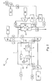
- This oxygen separating device 5 has an oxygen separating means an MCM membrane 6, which here by a dotted line is symbolized.
- This MCM membrane 6 separates in the oxygen separation device 5 a first chamber 7 from a second chamber 8, the first chamber 7 a passage side 9 and the second chamber 8 a retaining side 10 of the Membrane 6 is assigned.
- combustion exhaust gases 11 the one on an output side 12 of the burner 2 in an associated Enter exhaust pipe 13.
- combustion gases 11 can be used as hot working gases in a subsequent process become.
- a return line 15 branches off from the exhaust line 13 and leads to a first one Input 16 of the oxygen separation device 5 is connected. Through this first inlet 16 can branch off exhaust gas 17 into the first chamber 7, that is pass through side 9 of membrane 6.
- oxygen-containing gas 19 e.g. Air
- the oxygen-containing gas 19 is heated, so that from a first outlet 22 of the heat exchanger 3 heated oxygen-containing gas 20 exits.
- the first outlet 22 of the heat exchanger 3 has a second inlet 23 Oxygen separator 5 connected so that the heated, oxygen-containing Gas 20 thus enters the second chamber 8 on the retention side 10 of the membrane 6.
- the MCM membrane 6 now causes a transport of oxygen from the Retention side 10 to the passage side 9 Gas 20 deprived of oxygen, which reduces its oxygen content.
- oxygen is supplied to the branched exhaust gas 17, whereby this is enriched with oxygen.
- a first outlet 24 of the oxygen separation device 5 occurs accordingly oxygen-enriched, branched Exhaust gas 25 from the first chamber 7 and is via a line 26 a second input 27 of the heat exchanger 3 is supplied.
- the oxygen-enriched, recirculated exhaust gas 25 is cooled.
- the second outlet 28 of the heat exchanger 3 is cooled with Exhaust gas enriched with oxygen 29.
- 29 is used by the compressor 4. Since this is supplied to the compressor 4 Gas a relatively low temperature e.g. is less than 800 ° C, can the compressor 4 as a mechanical compressor or compressor or Pump or blower be formed.
- the cooled, enriched exhaust gas 29 is fed in via a feed line 60 which the compressor 4 is arranged, fed to an input side 30 of the burner 2.
- the input side 30 of the burner 2 also becomes fuel or a Fuel-vapor mixture 31 supplied, which reaches the device 1 at 32.
- a combustion mixture is then formed from the oxygen enriched, recirculated exhaust gases 29 and the supplied fuel 31.
- This combustion mixture burns in burner 2, making the desired hot combustion gases 11 arise.
- Oxygen-containing material emerges from a second outlet 33 of the oxygen separation device 5 Gas 34 out, which now has a reduced oxygen content.
- the temperature of the heated, oxygen-containing gases 20 is not sufficient to to ensure proper oxygen transport through the membrane 6.
- a suitable heating of the membrane 6 is achieved in that the recirculated or branched exhaust gases 17 relatively uncooled the oxygen separation device 5 are supplied.
- the membrane 6 When flowing through the chambers 7 and 8, the membrane 6 also serves as a heat transfer medium, which is a cooling the gases in the first chamber 7 and a heating of the gases in the second Chamber 8 causes. Accordingly, this is at 35 from device 1 escaping oxygen-containing gas 34 is relatively hot. This hot, oxygenated too Gas 34 can therefore be used as the working gas.
- the two chambers 7 and 8 are aligned are flowed through, as a result of which temperature stresses in the membrane 6 are as low as possible.
- Is on the input side of the oxygen separation device 5 the temperature of the membrane 6 between the higher temperature of the returned Exhaust gases 17 and the lower temperature of the heated oxygen-containing Gases 20. Until they exit the oxygen separator 5, they are the same the temperatures of membrane 6, exhaust gas 17 and gas 20 against each other.
- the device 1 forms a unit symbolized by the frame, into the entry points 18 and 32 oxygen-containing air 19 or fuel 31 enters and exits at the exit points 14 and 35 hot working gases, namely hot combustion gases 11 and hot oxygen-containing gases 34, escape.
- the device 1 has no interaction with previous ones or subsequent processes. Accordingly, the optimization the processes running within the device 1 independently of the preceding or subsequent processes are carried out, whereby the optimization of the device 1 is considerably simplified.
- the device 1 according to the invention can be used in a gas turbine system 36 be integrated, which serves to generate electricity. 2 it is clear like the entry points 18 and 32 and the exit points 14 and 35 as it were Form interfaces with which the device 1 according to the invention in the gas turbine system 36 is involved.
- a compressor 37 compresses ambient air 38, which heats up at the same time becomes.
- the compressed and heated ambient air forms the oxygen-containing one Gas 19, which is supplied to device 1 at 18.
- the heated, oxygen-poor air 34 emerges from device 1 at 35 and is fed to a turbine 39 which connected to the compressor 37 and a generator 40 for power generation is.
- the gas 34 fed to the turbine 39 is expanded in the turbine 39 and forms a relaxed flow 41, the heat of which is generated in a steam generator 42 is at least partially recovered. Then emerges from the steam generator 42 cooled, low-oxygen gas 43, which can then be further processed.
- fuel or fuel-vapor mixture 31 is supplied to device 1, this fuel 31 burning inside device 1 - as described above - with the oxygen of oxygen-containing gas 19.
- the resulting combustion essentially produces only CO 2 and H 2 O and forms the desired hot combustion exhaust gases 11, which leave the device 1 at 14.
- the hot combustion exhaust gases 11 are expanded in a turbine 44, which drives a further generator 45 for generating electricity.
- relaxed combustion exhaust gases 46 are formed, which are also fed to the steam generator 42.
- the steam generator 42 contains two separate chambers 47 and 48 for the relaxed, low-oxygen gases 41 and for the relaxed combustion exhaust gases 46.
- Cooled combustion exhaust gas 49 now emerges from the steam generator 42 and can be fed to a cooler 50 in which water vapor is condensed , Water 51 which is formed in the process is fed back to the steam generator 42.
- the remaining CO 2 52 leaves the cooler 50 and can be compressed in a compressor 53 and possibly liquefied.
- the compressed and / or liquid CO 2 54 can then be processed further.
- the compressor 53 is driven by a motor 55, for example. Coupling to turbine 44 is also conceivable, for example.
- the steam 56 generated by the steam generator 42 can be expanded in a turbine 57 that drives another generator 58 to generate electricity.
- the expanded steam can then condense in a condenser 59; that included Water formed can then be introduced into the steam generator 42.
- steam 56 may be mixed with fuel 31 to form a fuel-vapor mixture.
- combustion can thus take place fossil fuels are generated without pollutants like CO2, CO, NOx get into the environment.
Landscapes
- Engineering & Computer Science (AREA)
- Chemical & Material Sciences (AREA)
- Combustion & Propulsion (AREA)
- Mechanical Engineering (AREA)
- General Engineering & Computer Science (AREA)
- Analytical Chemistry (AREA)
- General Chemical & Material Sciences (AREA)
- Oil, Petroleum & Natural Gas (AREA)
- Chemical Kinetics & Catalysis (AREA)
- Separation Using Semi-Permeable Membranes (AREA)
- Feeding, Discharge, Calcimining, Fusing, And Gas-Generation Devices (AREA)
Abstract
Description
- Fig. 1
- eine schaltplanartige Prinzipdarstellung einer erfindungsgemäßen Vorrichtung und
- Fig. 2
- eine schaltplanartige Prinzipdarstellung einer Gasturbinenanlage, die eine erfindungsgemäße Vorrichtung enthält.
- 1
- Vorrichtung
- 2
- Brenner
- 3
- Wärmetauscher
- 4
- Verdichter
- 5
- Sauerstofftrenneinrichtung
- 6
- Sauerstofftrennmittel, MCM-Membran
- 7
- erste Kammer von 5
- 8
- zweite Kammer von 5
- 9
- Durchgangsseite von 6
- 10
- Rückhalteseite von 6
- 11
- heißes Verbrennungsabgas
- 12
- Ausgangsseite von 2
- 13
- Abgasleitung
- 14
- Austrittsstelle von 1
- 15
- Rückführungsleitung
- 16
- erster Eingang von 5
- 17
- abgezweigtes Abgas
- 18
- Eintrittsstelle von 1
- 19
- sauerstoffhaltiges Gas
- 20
- erwärmtes sauerstoffhaltiges Gas
- 21
- erster Eingang von 3
- 22
- erster Ausgang von 3
- 23
- zweiter Eingang von 5
- 24
- erster Ausgang von 5
- 25
- mit Sauerstoff angereichertes, abgezweigtes Abgas
- 26
- Leitung
- 27
- zweiter Eingang von 3
- 28
- zweiter Ausgang von 3
- 29
- gekühltes, mit Sauerstoff angereichertes, abgezweigtes Abgas
- 30
- Eingangsseite von 2
- 31
- Kraftstoff/Kraftstoff-Dampf-Gemisch
- 32
- Eintrittsstelle von 1
- 33
- zweiter Ausgang von 5
- 34
- heißes, bezüglich seines Sauerstoffgehaltes reduziertes Gas
- 35
- Austrittsstelle von 1
- 36
- Gasturbinenanlage
- 37
- Verdichter
- 38
- Umgebungsluft
- 39
- Turbine
- 40
- Generator
- 41
- entspanntes, heißes, sauerstoffarmes Gas
- 42
- Dampferzeuger
- 43
- gekühltes, sauerstoffarmes Gas
- 44
- Turbine
- 45
- Generator
- 46
- entspanntes Verbrennungsabgas
- 47
- erste Kammer von 42
- 48
- zweite Kammer von 42
- 49
- gekühltes Verbrennungsabgas
- 50
- Kühler
- 51
- Wasser
- 52
- CO2-Gas
- 53
- Verdichter
- 54
- verdichtetes und/oder flüssiges CO2
- 55
- Motor
- 56
- Dampf
- 57
- Turbine
- 58
- Generator
- 59
- Kondensator
- 60
- Zuführungsleitung
Claims (7)
- Verfahren zur Erzeugung heißer Arbeitsgase, insbesondere für eine Gasturbinenanlage,dadurch gekennzeichnet, dass das mit Sauerstoff angereicherte, abgezweigte Abgas (25), bevor es dem Brenner (2) zugeführt wird, zur Erhitzung des sauerstoffhaltigen Gases (19) verwendet wird.wobei in einem Brenner (2) eine Verbrennung stattfindet, die heißes Verbrennungsabgas (11) erzeugt, das zumindest teilweise als heißes Arbeitsgas verwendbar ist,wobei ein Teil (17) des Verbrennungsabgases (11) abgezweigt und einer Sauerstofftrenneinrichtung (5) zugeführt wird,wobei sauerstoffhaltiges Gas (19) erwärmt wird, um erwärmtes sauerstoffhaltiges Gas (20) zu bilden,wobei das erwärmte sauerstoffhaltige Gas (20) ebenfalls der Sauerstofftrenneinrichtung (5) zugeführt wird,wobei die Sauerstofftrenneinrichtung (5) Sauerstofftrennmittel (6) aufweist, die dem heißen sauerstoffhaltigen Gas (20) Sauerstoff entnehmen und dem abgezweigten Abgas (17) zuführen,wobei bezüglich seines Sauerstoffgehalts reduziertes, heißes Gas (34) die Sauerstofftrenneinrichtung (5) verlässt,wobei mit Sauerstoff angereichertes, abgezweigtes Abgas (25) sowie ein Kraftstoff (31) oder ein Kraftstoff-Dampf-Gemisch dem Brenner (2) zugeführt werden und ein Verbrennungsgemisch bilden, das im Brenner (2) unter Ausbildung des heißen Verbrennungsabgases (11) verbrennt, das den Brenner (2) verlässt und als heißes Arbeitsgas verwendbar ist,
- Verfahren nach Anspruch 1, dadurch gekennzeichnet, dass zur Wärmeübertragung von mit Sauerstoff angereichertem, abgezweigtem Abgas (25) an das sauerstoffhaltige Gas (19) ein Wärmetauscher (3) vorgesehen ist, wobei das mit Sauerstoff angereicherte, abgezweigte Abgas (25) und das sauerstoffhaltige Gas (19) den Wärmetauscher (3) nach dem Gegenstrom-Prinzip durchströmen.
- Verfahren nach Anspruch 1 oder 2 dadurch gekennzeichnet, dass das abgezweigte Abgas (17) und das erwärmte, sauerstoffhaltige Gas (20) die Sauerstofftrenneinrichtung (5) nach dem Gleichstrom-Prinzip durchströmen.
- Vorrichtung zur Erzeugung heißer Arbeitsgase, insbesondere für eine Gasturbinenanlage,dadurch gekennzeichnet, dass4.1. mit einem Brenner (2),4.1.1. der an einer Eingangsseite (30) mit Kraftstoff (31) oder Kraftstoff-Dampf-Gemisch und mit sauerstoffhaltigem Gas (29) versorgt wird,4.1.2. in dem ein Verbrennungsgemisch aus sauerstoffhaltigem Gas (29) und Kraftstoff (31) oder Kraftstoff-Dampf-Gemisch verbrennt und heißes Verbrennungsabgas (11) bildet,4.1.3. der an seiner Ausgangsseite (12) an eine Abgasleitung (13) angeschlossen ist, durch die das heiße Verbrennungsabgas (11) aus dem Brenner (2) austritt und zumindest teilweise als heißes Arbeitsgas verwendbar ist,4.2 mit einer Sauerstofftrenneinrichtung (5),4.2.1. die an einem ersten Eingang (16) mit heißem Verbrennungsabgas (17) versorgt wird, das von der Abgasleitung (13) abgezweigt wird,4.2.2. die an einem zweiten Eingang (23) mit erwärmtem sauerstoffhaltigem Gas (20) versorgt wird,4.2.3 die Sauerstofftrennmittel (6) aufweist, die Sauerstoff vom erwärmten sauerstoffhaltigen Gas (20) zum abgezweigten Verbrennungsabgas (17) transportieren,4.2.4 die einen ersten Ausgang (24) aufweist, aus dem mit Sauerstoff angereichertes Verbrennungsabgas (25) zur Versorgung der Eingangsseite (30) des Brenners (2) austritt,4.2.5 die einen zweiten Ausgang (33) aufweist, aus dem bezüglich seines Sauerstoffgehalts reduziertes heißes Gas (34) austritt, das als heißes Arbeitsgas verwendbar ist,4.3. mit einem Wärmetauscher (3),4.3.1. in den an einem ersten Eingang (21) relativ kaltes sauerstoffhaltiges Gas (19) eintritt,4.3.2. aus dem an einem ersten Ausgang (22) erwärmtes sauerstoffhaltiges Gas (20) zur Versorgung des zweiten Eingangs (23) der Sauerstofftrenneinrichtung (5) austritt,4.3.3. wobei der erste Ausgang (22) des Wärmetauschers (3) mit dem zweiten Eingang (23) der Sauerstofftrenneinrichtung (5) verbunden ist,der Wärmetauscher (3) einen zweiten Eingang (27) aufweist, der mit dem ersten Ausgang (24) der Sauerstofftrenneinrichtung (5) verbunden ist,der Wärmetauscher (3) einen zweiten Ausgang (28) aufweist, aus dem gekühltes, mit Sauerstoff angereichertes Verbrennungsabgas (29) zur Versorgung des Brenners (2) austritt.
- Vorrichtung nach Anspruch 4, dadurch gekennzeichnet, dass der zweite Ausgang (28) des Wärmetauschers (3) über eine Zuführungsleitung (60) mit der Eingangsseite (30) des Brenners (2) verbunden ist, wobei in diese Zuführungsleitung (60) ein Verdichter oder Gebläse (4) angeordnet ist.
- Vorrichtung nach Anspruch 4 oder 5, dadurch gekennzeichnet, dass der Wärmetauscher (3) als Zwei-Kreis-Wärmetauscher ausgebildet und so angeschlossen ist, dass das mit Sauerstoff angereicherte Verbrennungsabgas (25) und das sauerstoffhaltige Gas (19) den Wärmetauscher (3) nach dem Gegenstromprinzip durchströmen.
- Vorrichtung nach einem der Ansprüche 4 bis 6, dadurch gekennzeichnet, dass die Sauerstofftrenneinrichtung (5) eine erste Kammer (7) und eine zweite Kammer (8) aufweist und dass die Sauerstofftrennmittel eine Membran (6) aufweisen, welche die beiden Kammern (7, 8) voneinander trennt und Sauerstoff von der einen Kammer (8) in die andere Kammer (7) transportiert, wobei beide Kammern (7, 8) gleichgerichtet und parallel zur Membran (6) durchströmt werden.
Applications Claiming Priority (4)
| Application Number | Priority Date | Filing Date | Title |
|---|---|---|---|
| US23988700P | 2000-10-13 | 2000-10-13 | |
| US239887P | 2000-10-13 | ||
| CH5142001 | 2001-03-21 | ||
| CH5142001 | 2001-03-21 |
Publications (2)
| Publication Number | Publication Date |
|---|---|
| EP1197257A1 true EP1197257A1 (de) | 2002-04-17 |
| EP1197257B1 EP1197257B1 (de) | 2009-11-04 |
Family
ID=25737497
Family Applications (1)
| Application Number | Title | Priority Date | Filing Date |
|---|---|---|---|
| EP01122823A Expired - Lifetime EP1197257B1 (de) | 2000-10-13 | 2001-09-22 | Verfahren und Vorrichtung zur Erzeugung heisser Arbeitsgase |
Country Status (5)
| Country | Link |
|---|---|
| US (1) | US6510693B2 (de) |
| EP (1) | EP1197257B1 (de) |
| DE (1) | DE50115201D1 (de) |
| DK (1) | DK1197257T3 (de) |
| NO (1) | NO335351B1 (de) |
Cited By (3)
| Publication number | Priority date | Publication date | Assignee | Title |
|---|---|---|---|---|
| WO2004094909A1 (de) | 2003-04-24 | 2004-11-04 | Alstom Technology Ltd | Verfahren und vorrichtung zum betreiben eines brenners einer wärmekraftmaschine, insbesondere einer gasturbinenanlage |
| WO2007060209A1 (en) * | 2005-11-23 | 2007-05-31 | Siemens Aktiengesellschaft | Combustion installation |
| WO2008087150A1 (en) * | 2007-01-19 | 2008-07-24 | Siemens Aktiengesellschaft | Combustion installation |
Families Citing this family (7)
| Publication number | Priority date | Publication date | Assignee | Title |
|---|---|---|---|---|
| CA2493605A1 (en) * | 2001-07-25 | 2003-02-06 | Richard A. Haase | Processes and apparatus for the manufacture of polynuclear aluminum compounds and disinfectants, and polynuclear aluminum compounds and disinfectants from such processes and apparatus |
| WO2003087564A1 (en) | 2002-04-11 | 2003-10-23 | Haase Richard A | Water combustion technology-methods, processes, systems and apparatus for the combustion of hydrogen and oxygen |
| US20060149423A1 (en) * | 2004-11-10 | 2006-07-06 | Barnicki Scott D | Method for satisfying variable power demand |
| US8268269B2 (en) * | 2006-01-24 | 2012-09-18 | Clearvalue Technologies, Inc. | Manufacture of water chemistries |
| WO2009004307A1 (en) * | 2007-07-04 | 2009-01-08 | Jacobs Engineering U.K. Limited | Process for the separation of pressurised carbon dioxide from steam |
| GB2485789B (en) * | 2010-11-23 | 2014-03-12 | Nebb Engineering As | Method and system for energy efficient conversion of a carbon containing fuel to CO2 and H2O |
| CA2857323C (en) * | 2013-07-19 | 2019-09-03 | Conocophillips Company | Method for removing trace levels of oxygen from direct combustion device combustion products |
Citations (8)
| Publication number | Priority date | Publication date | Assignee | Title |
|---|---|---|---|---|
| US5753007A (en) | 1995-06-07 | 1998-05-19 | Air Products And Chemicals, Inc. | Oxygen production by ion transport membranes with non-permeate work recovery |
| EP0882486A1 (de) * | 1997-06-05 | 1998-12-09 | Praxair Technology, Inc. | Verfahren zur angereicherten Verbrennung unter Verwendung von Systemen mit einer festen elektrolytischen Membran |
| WO1998055208A1 (en) | 1997-06-06 | 1998-12-10 | Norsk Hydro Asa | Process for generating power including a combustion process |
| WO1998055394A1 (en) | 1997-06-06 | 1998-12-10 | Norsk Hydro Asa | Process for generating power and/or heat comprising a mixed conducting membrane reactor |
| DE19755116C1 (de) * | 1997-12-11 | 1999-03-04 | Dbb Fuel Cell Engines Gmbh | PEM-Brennstoffzellensystem sowie Verfahren zum Betreiben eines PEM-Brennstoffzellensystems |
| US5976223A (en) | 1997-11-18 | 1999-11-02 | Praxair Technology, Inc. | Solid electrolyte ionic conductor systems for oxygen, nitrogen, and/or carbon dioxide production with gas turbine |
| WO2000033942A1 (en) | 1998-12-04 | 2000-06-15 | Norsk Hydro Asa | Method for recovering co¿2? |
| EP1181968A2 (de) | 2000-08-21 | 2002-02-27 | Praxair Technology, Inc. | Gastrennungverfahren unter Verwendung von keramischen Membranen und Regenerierungseinrichtungen |
Family Cites Families (3)
| Publication number | Priority date | Publication date | Assignee | Title |
|---|---|---|---|---|
| US4341069A (en) * | 1980-04-02 | 1982-07-27 | Mobil Oil Corporation | Method for generating power upon demand |
| US4434613A (en) * | 1981-09-02 | 1984-03-06 | General Electric Company | Closed cycle gas turbine for gaseous production |
| US6298084B1 (en) * | 1998-11-24 | 2001-10-02 | Motorola, Inc. | Bad frame detector and turbo decoder |
-
2001
- 2001-09-22 DK DK01122823.6T patent/DK1197257T3/da active
- 2001-09-22 DE DE50115201T patent/DE50115201D1/de not_active Expired - Lifetime
- 2001-09-22 EP EP01122823A patent/EP1197257B1/de not_active Expired - Lifetime
- 2001-10-12 US US09/975,307 patent/US6510693B2/en not_active Expired - Lifetime
- 2001-10-12 NO NO20014982A patent/NO335351B1/no not_active IP Right Cessation
Patent Citations (8)
| Publication number | Priority date | Publication date | Assignee | Title |
|---|---|---|---|---|
| US5753007A (en) | 1995-06-07 | 1998-05-19 | Air Products And Chemicals, Inc. | Oxygen production by ion transport membranes with non-permeate work recovery |
| EP0882486A1 (de) * | 1997-06-05 | 1998-12-09 | Praxair Technology, Inc. | Verfahren zur angereicherten Verbrennung unter Verwendung von Systemen mit einer festen elektrolytischen Membran |
| WO1998055208A1 (en) | 1997-06-06 | 1998-12-10 | Norsk Hydro Asa | Process for generating power including a combustion process |
| WO1998055394A1 (en) | 1997-06-06 | 1998-12-10 | Norsk Hydro Asa | Process for generating power and/or heat comprising a mixed conducting membrane reactor |
| US5976223A (en) | 1997-11-18 | 1999-11-02 | Praxair Technology, Inc. | Solid electrolyte ionic conductor systems for oxygen, nitrogen, and/or carbon dioxide production with gas turbine |
| DE19755116C1 (de) * | 1997-12-11 | 1999-03-04 | Dbb Fuel Cell Engines Gmbh | PEM-Brennstoffzellensystem sowie Verfahren zum Betreiben eines PEM-Brennstoffzellensystems |
| WO2000033942A1 (en) | 1998-12-04 | 2000-06-15 | Norsk Hydro Asa | Method for recovering co¿2? |
| EP1181968A2 (de) | 2000-08-21 | 2002-02-27 | Praxair Technology, Inc. | Gastrennungverfahren unter Verwendung von keramischen Membranen und Regenerierungseinrichtungen |
Cited By (3)
| Publication number | Priority date | Publication date | Assignee | Title |
|---|---|---|---|---|
| WO2004094909A1 (de) | 2003-04-24 | 2004-11-04 | Alstom Technology Ltd | Verfahren und vorrichtung zum betreiben eines brenners einer wärmekraftmaschine, insbesondere einer gasturbinenanlage |
| WO2007060209A1 (en) * | 2005-11-23 | 2007-05-31 | Siemens Aktiengesellschaft | Combustion installation |
| WO2008087150A1 (en) * | 2007-01-19 | 2008-07-24 | Siemens Aktiengesellschaft | Combustion installation |
Also Published As
| Publication number | Publication date |
|---|---|
| NO20014982D0 (no) | 2001-10-12 |
| US20020124558A1 (en) | 2002-09-12 |
| NO335351B1 (no) | 2014-11-24 |
| DE50115201D1 (de) | 2009-12-17 |
| DK1197257T3 (da) | 2010-03-22 |
| EP1197257B1 (de) | 2009-11-04 |
| US6510693B2 (en) | 2003-01-28 |
| NO20014982L (no) | 2002-04-15 |
Similar Documents
| Publication | Publication Date | Title |
|---|---|---|
| DE69717161T2 (de) | Verfahren zur energiegewinnung mit hilfe eines verbrennungsprozesses | |
| DE60219513T2 (de) | Sauerstoffbefeuerter zirkulierender wirbelschichtdampferzeuger | |
| DE60006305T2 (de) | Gasturbinensystem | |
| EP1197258B1 (de) | Verfahren zum Betrieb einer Kraftwerksanlage | |
| DE69829132T2 (de) | Verfahren zur angereicherten Verbrennung unter Verwendung von Festelektrolyt-Ionenleitsystemen | |
| DE69102577T2 (de) | Kraftanlage. | |
| DE69910441T2 (de) | Verfahren zur wiedergewinnung von kohlendioxid | |
| DE69635965T2 (de) | Sauerstoffproduktion mit Ionentransportmembranen unter Verwendung von Dampf | |
| DE69808218T2 (de) | Verfahren mit festen elektrolytischen Ionenleitern zur Erzeugung von Sauerstoff, Stickstoff und/oder Kohlendioxid für Gasturbirnen | |
| EP0553125A1 (de) | Verfahren und anlage zur kombinierten erzeugung elektrischer und mechanischer energie. | |
| CH698466A2 (de) | Verbrennungssystem mit Gasturbine und Sauerstoffquelle. | |
| DE102004039164A1 (de) | Verfahren zur Erzeugung von Energie in einer eine Gasturbine umfassenden Energieerzeugungsanlage sowie Energieerzeugungsanlage zur Durchführung des Verfahrens | |
| DE2849151A1 (de) | Brennstoffzellenstromversorgungsanlage und verfahren zum betreiben derselben | |
| CH697901B1 (de) | Polygenerationsanordnung. | |
| DE10328863A1 (de) | Befeuerungsverfahren für eine Wärme verbrauchende Vorrichtung unter Verwendung einer Sauerstoff-Brennstoff-Verbrennung | |
| EP1197256A1 (de) | Verfahren und Vorrichtung zur Erzeugung von heissen Verbrennungsabgasen | |
| EP1717420B1 (de) | Kraftwerksanlage mit Luftzerlegungsanlage | |
| DE10244883B4 (de) | Heizsystem für ein Fahrzeug | |
| EP1197257B1 (de) | Verfahren und Vorrichtung zur Erzeugung heisser Arbeitsgase | |
| WO2023245220A2 (de) | Brennstoffzellensystem, brennstoffzellenanlage und verfahren zum erzeugen von synthesegas | |
| DE102007019178A1 (de) | Verfahren zur Konzentration von Kohlendioxid, das in Rauchgasen vorhanden ist, die von einer Anlage zur Energieerzeugung abgegeben werden | |
| EP4496913B1 (de) | Hochtemperatur-co-elektrolysesystem, hochtemperatur-co-elektrolyseanlage und verfahren zum erzeugen von synthesegas | |
| WO2011020767A1 (de) | Verfahren und vorrichtung zur verwertung von biomassse | |
| EP1518040A1 (de) | Dampfkraftwerk | |
| CH701210A1 (de) | Verfahren zum Betrieb eines Gasturbinenkraftwerkes mit Brennstoffzelle. |
Legal Events
| Date | Code | Title | Description |
|---|---|---|---|
| PUAI | Public reference made under article 153(3) epc to a published international application that has entered the european phase |
Free format text: ORIGINAL CODE: 0009012 |
|
| AK | Designated contracting states |
Kind code of ref document: A1 Designated state(s): DE DK GB SE Kind code of ref document: A1 Designated state(s): AT BE CH CY DE DK ES FI FR GB GR IE IT LI LU MC NL PT SE TR |
|
| AX | Request for extension of the european patent |
Free format text: AL;LT;LV;MK;RO;SI |
|
| 17P | Request for examination filed |
Effective date: 20020911 |
|
| AKX | Designation fees paid |
Free format text: DE DK GB SE |
|
| RAP1 | Party data changed (applicant data changed or rights of an application transferred) |
Owner name: ALSTOM TECHNOLOGY LTD |
|
| 17Q | First examination report despatched |
Effective date: 20070518 |
|
| GRAP | Despatch of communication of intention to grant a patent |
Free format text: ORIGINAL CODE: EPIDOSNIGR1 |
|
| GRAS | Grant fee paid |
Free format text: ORIGINAL CODE: EPIDOSNIGR3 |
|
| RIN1 | Information on inventor provided before grant (corrected) |
Inventor name: LINDER, ULF Inventor name: WINKLER, DIETER Inventor name: GRIFFIN, TIMOTHY ALBERT, DR. |
|
| GRAA | (expected) grant |
Free format text: ORIGINAL CODE: 0009210 |
|
| AK | Designated contracting states |
Kind code of ref document: B1 Designated state(s): DE DK GB SE |
|
| REG | Reference to a national code |
Ref country code: GB Ref legal event code: FG4D Free format text: NOT ENGLISH |
|
| REF | Corresponds to: |
Ref document number: 50115201 Country of ref document: DE Date of ref document: 20091217 Kind code of ref document: P |
|
| REG | Reference to a national code |
Ref country code: SE Ref legal event code: TRGR |
|
| REG | Reference to a national code |
Ref country code: DK Ref legal event code: T3 |
|
| PLBE | No opposition filed within time limit |
Free format text: ORIGINAL CODE: 0009261 |
|
| STAA | Information on the status of an ep patent application or granted ep patent |
Free format text: STATUS: NO OPPOSITION FILED WITHIN TIME LIMIT |
|
| 26N | No opposition filed |
Effective date: 20100805 |
|
| REG | Reference to a national code |
Ref country code: DE Ref legal event code: R082 Ref document number: 50115201 Country of ref document: DE Representative=s name: ROESLER, UWE, DIPL.-PHYS.UNIV., DE Ref country code: DE Ref legal event code: R081 Ref document number: 50115201 Country of ref document: DE Owner name: GENERAL ELECTRIC TECHNOLOGY GMBH, CH Free format text: FORMER OWNER: ALSTOM TECHNOLOGY LTD., BADEN, CH Ref country code: DE Ref legal event code: R081 Ref document number: 50115201 Country of ref document: DE Owner name: ANSALDO ENERGIA SWITZERLAND AG, CH Free format text: FORMER OWNER: ALSTOM TECHNOLOGY LTD., BADEN, CH |
|
| PGFP | Annual fee paid to national office [announced via postgrant information from national office to epo] |
Ref country code: DK Payment date: 20160920 Year of fee payment: 16 |
|
| REG | Reference to a national code |
Ref country code: GB Ref legal event code: 732E Free format text: REGISTERED BETWEEN 20170727 AND 20170802 |
|
| REG | Reference to a national code |
Ref country code: DE Ref legal event code: R082 Ref document number: 50115201 Country of ref document: DE Representative=s name: ROESLER, UWE, DIPL.-PHYS.UNIV., DE Ref country code: DE Ref legal event code: R081 Ref document number: 50115201 Country of ref document: DE Owner name: ANSALDO ENERGIA SWITZERLAND AG, CH Free format text: FORMER OWNER: GENERAL ELECTRIC TECHNOLOGY GMBH, BADEN, CH |
|
| PGFP | Annual fee paid to national office [announced via postgrant information from national office to epo] |
Ref country code: DE Payment date: 20170928 Year of fee payment: 17 Ref country code: GB Payment date: 20170921 Year of fee payment: 17 |
|
| PGFP | Annual fee paid to national office [announced via postgrant information from national office to epo] |
Ref country code: SE Payment date: 20170921 Year of fee payment: 17 |
|
| REG | Reference to a national code |
Ref country code: DK Ref legal event code: EBP Effective date: 20170930 |
|
| PG25 | Lapsed in a contracting state [announced via postgrant information from national office to epo] |
Ref country code: DK Free format text: LAPSE BECAUSE OF NON-PAYMENT OF DUE FEES Effective date: 20170930 |
|
| REG | Reference to a national code |
Ref country code: DE Ref legal event code: R119 Ref document number: 50115201 Country of ref document: DE |
|
| REG | Reference to a national code |
Ref country code: SE Ref legal event code: EUG |
|
| GBPC | Gb: european patent ceased through non-payment of renewal fee |
Effective date: 20180922 |
|
| PG25 | Lapsed in a contracting state [announced via postgrant information from national office to epo] |
Ref country code: SE Free format text: LAPSE BECAUSE OF NON-PAYMENT OF DUE FEES Effective date: 20180923 |
|
| PG25 | Lapsed in a contracting state [announced via postgrant information from national office to epo] |
Ref country code: DE Free format text: LAPSE BECAUSE OF NON-PAYMENT OF DUE FEES Effective date: 20190402 |
|
| PG25 | Lapsed in a contracting state [announced via postgrant information from national office to epo] |
Ref country code: GB Free format text: LAPSE BECAUSE OF NON-PAYMENT OF DUE FEES Effective date: 20180922 |