EP1196970B1 - Procede de pompage optique d'un milieu amplificateur de lumiere et module de pompage optique pour la mise en oeuvre de ce procede - Google Patents
Procede de pompage optique d'un milieu amplificateur de lumiere et module de pompage optique pour la mise en oeuvre de ce procede Download PDFInfo
- Publication number
- EP1196970B1 EP1196970B1 EP00958617A EP00958617A EP1196970B1 EP 1196970 B1 EP1196970 B1 EP 1196970B1 EP 00958617 A EP00958617 A EP 00958617A EP 00958617 A EP00958617 A EP 00958617A EP 1196970 B1 EP1196970 B1 EP 1196970B1
- Authority
- EP
- European Patent Office
- Prior art keywords
- reflector
- light
- wall
- amplifying medium
- source
- Prior art date
- Legal status (The legal status is an assumption and is not a legal conclusion. Google has not performed a legal analysis and makes no representation as to the accuracy of the status listed.)
- Expired - Lifetime
Links
Images

Classifications
-
- H—ELECTRICITY
- H01—ELECTRIC ELEMENTS
- H01S—DEVICES USING THE PROCESS OF LIGHT AMPLIFICATION BY STIMULATED EMISSION OF RADIATION [LASER] TO AMPLIFY OR GENERATE LIGHT; DEVICES USING STIMULATED EMISSION OF ELECTROMAGNETIC RADIATION IN WAVE RANGES OTHER THAN OPTICAL
- H01S3/00—Lasers, i.e. devices using stimulated emission of electromagnetic radiation in the infrared, visible or ultraviolet wave range
- H01S3/09—Processes or apparatus for excitation, e.g. pumping
- H01S3/091—Processes or apparatus for excitation, e.g. pumping using optical pumping
- H01S3/094—Processes or apparatus for excitation, e.g. pumping using optical pumping by coherent light
- H01S3/0941—Processes or apparatus for excitation, e.g. pumping using optical pumping by coherent light of a laser diode
-
- H—ELECTRICITY
- H01—ELECTRIC ELEMENTS
- H01S—DEVICES USING THE PROCESS OF LIGHT AMPLIFICATION BY STIMULATED EMISSION OF RADIATION [LASER] TO AMPLIFY OR GENERATE LIGHT; DEVICES USING STIMULATED EMISSION OF ELECTROMAGNETIC RADIATION IN WAVE RANGES OTHER THAN OPTICAL
- H01S3/00—Lasers, i.e. devices using stimulated emission of electromagnetic radiation in the infrared, visible or ultraviolet wave range
- H01S3/02—Constructional details
- H01S3/025—Constructional details of solid state lasers, e.g. housings or mountings
-
- H—ELECTRICITY
- H01—ELECTRIC ELEMENTS
- H01S—DEVICES USING THE PROCESS OF LIGHT AMPLIFICATION BY STIMULATED EMISSION OF RADIATION [LASER] TO AMPLIFY OR GENERATE LIGHT; DEVICES USING STIMULATED EMISSION OF ELECTROMAGNETIC RADIATION IN WAVE RANGES OTHER THAN OPTICAL
- H01S3/00—Lasers, i.e. devices using stimulated emission of electromagnetic radiation in the infrared, visible or ultraviolet wave range
- H01S3/05—Construction or shape of optical resonators; Accommodation of active medium therein; Shape of active medium
- H01S3/06—Construction or shape of active medium
- H01S3/0602—Crystal lasers or glass lasers
- H01S3/061—Crystal lasers or glass lasers with elliptical or circular cross-section and elongated shape, e.g. rod
-
- H—ELECTRICITY
- H01—ELECTRIC ELEMENTS
- H01S—DEVICES USING THE PROCESS OF LIGHT AMPLIFICATION BY STIMULATED EMISSION OF RADIATION [LASER] TO AMPLIFY OR GENERATE LIGHT; DEVICES USING STIMULATED EMISSION OF ELECTROMAGNETIC RADIATION IN WAVE RANGES OTHER THAN OPTICAL
- H01S3/00—Lasers, i.e. devices using stimulated emission of electromagnetic radiation in the infrared, visible or ultraviolet wave range
- H01S3/09—Processes or apparatus for excitation, e.g. pumping
- H01S3/091—Processes or apparatus for excitation, e.g. pumping using optical pumping
- H01S3/094—Processes or apparatus for excitation, e.g. pumping using optical pumping by coherent light
-
- H—ELECTRICITY
- H01—ELECTRIC ELEMENTS
- H01S—DEVICES USING THE PROCESS OF LIGHT AMPLIFICATION BY STIMULATED EMISSION OF RADIATION [LASER] TO AMPLIFY OR GENERATE LIGHT; DEVICES USING STIMULATED EMISSION OF ELECTROMAGNETIC RADIATION IN WAVE RANGES OTHER THAN OPTICAL
- H01S3/00—Lasers, i.e. devices using stimulated emission of electromagnetic radiation in the infrared, visible or ultraviolet wave range
- H01S3/09—Processes or apparatus for excitation, e.g. pumping
- H01S3/091—Processes or apparatus for excitation, e.g. pumping using optical pumping
- H01S3/094—Processes or apparatus for excitation, e.g. pumping using optical pumping by coherent light
- H01S3/094049—Guiding of the pump light
- H01S3/094053—Fibre coupled pump, e.g. delivering pump light using a fibre or a fibre bundle
-
- H—ELECTRICITY
- H01—ELECTRIC ELEMENTS
- H01S—DEVICES USING THE PROCESS OF LIGHT AMPLIFICATION BY STIMULATED EMISSION OF RADIATION [LASER] TO AMPLIFY OR GENERATE LIGHT; DEVICES USING STIMULATED EMISSION OF ELECTROMAGNETIC RADIATION IN WAVE RANGES OTHER THAN OPTICAL
- H01S3/00—Lasers, i.e. devices using stimulated emission of electromagnetic radiation in the infrared, visible or ultraviolet wave range
- H01S3/09—Processes or apparatus for excitation, e.g. pumping
- H01S3/091—Processes or apparatus for excitation, e.g. pumping using optical pumping
- H01S3/094—Processes or apparatus for excitation, e.g. pumping using optical pumping by coherent light
- H01S3/094049—Guiding of the pump light
- H01S3/094057—Guiding of the pump light by tapered duct or homogenized light pipe, e.g. for concentrating pump light
-
- H—ELECTRICITY
- H01—ELECTRIC ELEMENTS
- H01S—DEVICES USING THE PROCESS OF LIGHT AMPLIFICATION BY STIMULATED EMISSION OF RADIATION [LASER] TO AMPLIFY OR GENERATE LIGHT; DEVICES USING STIMULATED EMISSION OF ELECTROMAGNETIC RADIATION IN WAVE RANGES OTHER THAN OPTICAL
- H01S3/00—Lasers, i.e. devices using stimulated emission of electromagnetic radiation in the infrared, visible or ultraviolet wave range
- H01S3/09—Processes or apparatus for excitation, e.g. pumping
- H01S3/091—Processes or apparatus for excitation, e.g. pumping using optical pumping
- H01S3/094—Processes or apparatus for excitation, e.g. pumping using optical pumping by coherent light
- H01S3/094084—Processes or apparatus for excitation, e.g. pumping using optical pumping by coherent light with pump light recycling, i.e. with reinjection of the unused pump light, e.g. by reflectors or circulators
Definitions
- the present invention relates to a method for Optical pumping of a light-amplifying medium as well as an optical pumping module for the implementation of this process.
- a laser based on the invention finds industrial applications especially in the fields following: welding, cutting, surface treatment of materials and marking of objects.
- the energy needed to operate a laser can be supplied to the amplifier medium of electrically, chemically or optically.
- the light distribution of pumping in the middle amplifier should be the most homogeneous possible.
- the amplifying medium of a laser absorbs all or part of the pumping power and re-emits a certain amount in form stimulated emission, the rest of the power absorbed being transformed into heat. This stimulated emission is called "laser effect”.
- Absorption of pumping power follows an exponential law (Beer-Lambert law) which translated by a greater absorbed power on the part (or parts) of the amplifying medium close (s) to the source of pumping. This creates inhomogeneities of pumping: the absorbed power is not not the same in every point of the amplifying medium.
- This technique makes it possible to obtain a homogeneous distribution of pumping but it is not suitable for lasers of very high average power at causes thermal stress problems of the end of the amplifying medium. In fact this technique is especially suitable for single mode lasers transverse moderate average power.
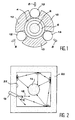
- FIG. 1 This is schematically illustrated by the Figure 1 where we see, in cross section, a laser bar 2 placed in a sapphire sleeve 4.
- the space between the bar 2 and the sleeve 4 constitutes a cooling channel 6.
- Three diodes 8 lasers are placed at 120 ° from each other around of the sleeve 4 and are separated from each other by copper spacers 10.
- Each diode 8 emits a light beam of optical pumping towards the bar 2 and one focus this beam on the bar via of a cylindrical lens 12.
- each diode only illuminates one limited part of the middle amplifier and homogeneity pumping that it is then possible to obtain depends directly from the degree of symmetry of the diode-bar system.
- US-A-5,619,522 discloses a method for optically pumping an amplifying medium according to the preamble of claim 1 and a module optical pumping device according to the preamble of claim 2.
- the present invention relates to a optical pumping method of an amplifying medium of light as well as an optical pumping module that allow a homogeneous distribution of this pumping, are usable to form a laser, whatever the desired power for this laser, and do not require not a lot of pumping light sources.
- the present invention has A method for optically pumping a medium light amplifier, in which least an optical pumping light source the middle amplifier and one surrounds this medium amplifier by a reflector whose wall (simple or multiple) is able to reflect the light of the source, and in which we send the beam directly from the source to the reflector wall so that this beam it undergoes successive reflections, and in which we place the medium amplifier outside this beam directly issued of the source so that this amplifying medium is optically pumped by light alone, reflected by the reflector wall, this method being characterized in that the reflector is partially or totally diffusing so that the beam undergoes on the reflector wall reflections partially or totally successive diffuses.
- the invention also relates to a module of optical pumping for an amplifying medium of light, comprising at least one light source of optical pumping of the amplifier medium and a reflector that surrounds this amplifying medium and whose the wall (single or multiple) is able to reflect the light from the source, the source being oriented so to send the beam directly from this source towards the wall of the reflector so that this beam undergo reflections successive and the middle amplifier being placed outside this beam directly from the source so that this environment amplifier is pumped optically by the only light reflected from the reflector wall, this module being characterized in that that the reflector is partially or totally diffusing so that the beam undergoes reflections on the wall of the reflector partially or completely diffuse successive.
- the amplifying medium forms a cylindrical bar substantially based circular
- the light source is intended for transversal optical pumping of this medium
- the wall of reflector forms a cylinder whose generators are parallel to the axis of the amplifying medium.
- the reflector has substantially the same length as the amplifier medium.
- the light source can be a transmitter from light.
- This light emitter can be chosen among a laser diode, a strip of laser diodes, a row of laser diode arrays, a stack of laser diode arrays and a combination of this row and this stack, this (or these) bar (s) being parallel to the generators of the cylinder that forms the wall of the reflector.
- the module which is the subject of the invention can also include several blocks, each block comprising a planar face, able to reflect, so partially or totally diffuse, the light of the source, the base of the cylinder formed by the wall of the reflector being a substantially regular polygon, this wall thus comprising several sides, each of these being formed by two respective flat faces two adjacent blocks.
- the light source can be placed in an interval formed between two adjacent blocks of way that light emerges from the space thus formed between the respective planar faces of these two blocks and reaches the wall of the reflector.
- the two blocks are electrically conductors and the laser diode or the laser diode array (s) is (or are) powered electrically through these two blocks.
- the light source can be a means of spreading light whose one end is intended to receive the light of a light emitter and of which another end is intended to send this light to the reflector wall.
- the reflector is almost Lambertian.
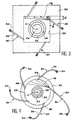
- An optical pumping module is schematically shown in section cross-section in FIG. 2 and comprises a medium light amplifier 14 and at least one source of light 16, for example a laser diode, this source preferably being quasi-punctual.
- Source 16 is intended to provide a light capable of optically pumping the medium amplifier 14.
- the module shown in Figure 2 also includes a reflector 20 which surrounds the medium amplifier and whose wall 22 is able to reflect this light diffusely. This reflector is almost lambertian preference.
- Source 16 which opens into space delimited by the reflector, is oriented so as to send, towards the wall 22 of this reflector, the beam bright 18 directly from this source 16. This beam 18 then undergoes diffuse reflections successive.
- the amplifying medium 14 is placed outside this beam directly from the source 16. As a result, this amplifying medium 14 is optically pumped only by the light diffused by the wall 22 of the reflector 20.
- optical pumping modules known transverse, light sources, for example laser diodes, emit directly into the direction of the amplifying medium.
- the homogeneity of pumping can only result from the sum of respective contributions of the laser diodes by effect of symmetry.
- the present invention goes against this principle: no source used in the invention does not emit light directly towards the middle amplifier. This is why the pumping process optical object of the invention can be considered as indirect pumping.
- the flow is distributed bright emitted by each pumping light source all around the amplifier medium through a reflector partially or fully diffusing so to avoid creating a privileged direction.
- This source is then not a localized source but an extended source that illuminates the medium amplifier in all directions.
- each source allows to obtain a virtually homogeneous pumping.
- the invention so there are fewer constraints of symmetry that in the prior art both for the mechanical positioning of sources only for sorting selective of these.
- This reflector can for example be made in ceramic type SINTOX-Al (registered trademark) or polymer of the SPECTRALON type (registered trademark) or be obtained by means of a surface treatment of a wall metallic, for example an INFRAGOLD type treatment (trademark) during which we sand the wall metal and then deposited a thin layer Golden.
- a surface treatment of a wall metallic for example an INFRAGOLD type treatment (trademark) during which we sand the wall metal and then deposited a thin layer Golden.
- a diffusing reflector 20 and a medium amplifier 24 in the form of a cylindrical bar with a base substantially circular are coaxial and have roughly the same length.
- These pumping modules are seen in cross section perpendicular to the X axis which is common to the amplifying medium and the reflector.
- a module according to the invention is usable not only in a laser (in the strict sense) but still in an amplification device of light where a laser beam passes through a medium light amplifier intended to amplify this beam.
- this amplifier medium 24 is solid. He is placed at the inside of a tube 26 which is transparent to the pumping light. In the interval 28 between this tube and the amplifying medium, we circulate, by means not shown, a liquid of transparent cooling to pumping light to cool the amplifying medium.
- the reflector 20 surrounds the tube 26 and therefore the amplifying medium 24 and the wall 22 of this reflector forms a cylinder whose generators are parallel to the X axis of the amplifying medium.
- FIGS. 3 to 5 uses one or more pumping light sources optical, for example one or more laser diodes having an emission spectrum in agreement with the spectrum absorption of the amplifying medium.
- the light thus injected into the room pumping is initially directed directly on the diffusing reflective material without go through the amplifier medium.
- the wall of the reflector is a square-based cylinder: we see on the figure the four sides of this wall.
- Each of these sources 30 includes a guide to light 32, for example a glass slide, which runs through the reflector parallel to the X axis as we see in Figure 3.
- This blade 32 opens inside the reflector and is flush with the wall of it while the second end of the blade opens out of this reflector.
- This second end is optically coupled to a laser diode 34 or to a bar of laser diodes parallel to the X axis which is controlled by means not shown.
- This diode or this diode array emits the pumping light that is then transported by the blade and goes out by the first end of this blade to illuminate the reflector wall.
- the reflector 20 has a cylindrical wall with a circular base.
- Each source includes an optical fiber 36 one end of which is optically coupled to a diode laser 34 controlled by means not shown and the other end of which is in a mouthpiece rectilinear 38 which crosses obliquely (that is to say not radially) the reflector to debouch in the space delimited by this reflector flush with the wall of this reflector.
- the reflector diffusing 20 has a cylindrical wall 22 based polygonal for example five-sided.
- light emitters 40 consisting of laser diode arrays that are parallel to the X axis of the amplifier bar 24.
- Figure 5 shows five groups of two metal blocks 42 and 44 respectively two plane faces 46 and 48 which are coplanar and whose the meeting is one of the sides of the wall 22 to pentagonal base of the module of FIG.
- Each strip of laser diodes is between the two metal blocks 42 and 44 of a same group and is in the vicinity of the faces respective 46 and 48 of these two blocks, on the line separating these two faces.
- an element 52 made of a material electrically insulating separates each block, belonging to a specific group of blocks, a block of the group adjacent to avoid electrical contact between these two blocks.
- all faces 46 and 48 are sanded and then coated with a thin layer of gold to get diffuse reflection.
Landscapes
- Physics & Mathematics (AREA)
- Electromagnetism (AREA)
- Engineering & Computer Science (AREA)
- Plasma & Fusion (AREA)
- Optics & Photonics (AREA)
- Lasers (AREA)
Abstract
Description
- la figure 1 illustre schématiquement une technique connue de pompage optique transverse d'un milieu amplificateur de lumière et a déjà été décrite,
- la figure 2 illustre schématiquement le principe de la présente invention,
- la figure 3 est une vue en coupe transversale schématique d'un premier mode de réalisation particulier du module de pompage optique objet de l'invention, utilisant un réflecteur à paroi cylindrique à base carrée,
- la figure 4 est une vue en coupe transversale schématique d'un deuxième mode de réalisation particulier du module de pompage optique objet de l'invention, utilisant un réflecteur diffusant à paroi cylindrique à base circulaire, et
- la figure 5 est une vue en coupe transversale schématique d'un troisième mode de réalisation particulier du module de pompage optique objet de l'invention, utilisant un réflecteur diffusant à paroi cylindrique à base polygonale.
- un barreau amplificateur en Nd:YAG de 5 mm de diamètre et d'indice optique 1,82,
- des diodes lasers dont la divergence totale à mi-hauteur vaut 40°, qui sont positionnées à 0,5 mm de leurs guides de lumière respectifs, émettent à 808 nm et ont une largeur spectrale de 2 nm à mi-hauteur,
- un tube de verre 26 de diamètre intérieur 7 mm et de diamètre extérieur 9 mm et d'indice optique 1,5, ce tube étant traité anti-reflet à l'extérieur,
- de l'eau de refroidissement d'indice optique égal à 1,33,
- un réflecteur à paroi carrée de 15 mm de côté et ayant un coefficient de réflexion de 97,5% et
- des guides de lumière en verre dont les dimensions valent 1 cmxl mm, qui ont un indice optique égal à 1,5 et dont les première et deuxième extrémités sont traitées anti-reflet.
Claims (12)
- Procédé de pompage optique d'un milieu amplificateur de lumière (14, 24), dans lequel on utilise au moins une source (14, 30, 40) de lumière de pompage optique du milieu amplificateur et l'on entoure ce milieu amplificateur par un réflecteur (20) dont la paroi (22) est apte à réfléchir la lumière de la source, et dans lequel on envoie le faisceau (18) ) directement issu de la source vers la paroi du réflecteur pour que ce faisceau y subisse des réflexions successives, et dans lequel on place le milieu amplificateur en dehors de ce faisceau directement issu de la source pour que ce milieu amplificateur soit pompé optiquement par la seule lumière réfléchie par la paroi du réflecteur ce procédé étant caractérisé en ce que le réflecteur est partiellement ou totalement diffusant pour que le faisceau subisse sur la paroi du réflecteur des réflexions partiellement ou totalement diffuses successives.
- Module de pompage optique comprenant un milieu amplificateur de lumière (14, 24), au moins une source (16, 30, 40) de lumière de pompage optique du milieu amplificateur et un réflecteur (20) qui entoure ce milieu amplificateur et dont la paroi (22) est apte à réfléchir la lumière de la source, la source étant orientée de façon à envoyer le faisceau (18) directement issu de cette source vers la paroi du réflecteur pour que ce faisceau y subisse des réflexions successives et le milieu amplificateur étant placé en dehors de ce faisceau directement issu de la source pour que ce milieu amplificateur soit pompé optiquement par la seule lumière réfléchie par la paroi du réflecteur ce module étant caractérisé en ce que le réflecteur est partiellement ou totalement diffusant pour que le faisceau subisse sur la paroi du réflecteur des réflexions partiellement ou totalement diffuses successives.
- Module selon la revendication 2, dans lequel le milieu amplificateur (24) forme un barreau cylindrique à base sensiblement circulaire, la source de lumière (30, 40) est destinée au pompage optique transversal de ce milieu et la paroi (22) du réflecteur (20) forme un cylindre dont les génératrices sont parallèles à l'axe (X) du milieu amplificateur.
- Module selon la revendication 3, dans lequel le réflecteur (20) a sensiblement la même longueur que le milieu amplificateur (24).
- Module selon l'une quelconque des revendications 3 et 4, dans lequel la base du cylindre formé par la paroi (22) du réflecteur est choisie parmi les polygones sensiblement réguliers, les ellipses et les cercles.
- Module selon l'une quelconque des revendication 3 à 5, dans lequel la source de lumière est un émetteur de lumière (16, 40) et cet émetteur de lumière est choisi parmi une diode laser, une barrette de diodes lasers, une rangée de barrettes de diodes laser, un empilement de barrettes de diodes lasers et une combinaison de cette rangée et de cet empilement, cette (ou ces) barrette(s) étant parallèle(s) aux génératrices du cylindre que forme la paroi du réflecteur.
- Module selon l'une quelconque des revendications 3 à 6, comprenant en outre plusieurs blocs (42, 44), chaque bloc comprenant une face plane (46, 48),apte à réfléchir de façon partiellement ou totalement diffuse la lumière de la source, la base du cylindre formé par la paroi du réflecteur étant un polygone sensiblement régulier, cette paroi comprenant ainsi plusieurs côtés, chacun de ceux-ci étant formé par deux faces planes respectives de deux blocs adjacents.
- Module selon la revendication 7, dans lequel la source de lumière (40) est placée dans un intervalle formé entre deux blocs adjacents (42, 44) de manière que la lumière émerge de l'espace ainsi formé entre les faces planes respectives de ces deux blocs et atteigne la paroi du réflecteur.
- Module selon les revendications 6 et 8, dans lequel les deux blocs (42, 44) sont électriquement conducteurs et la diode laser ou la (ou les) barrette(s) de diodes lasers (40) est (ou sont) alimentée(s) électriquement par l'intermédiaire de ces deux blocs.
- Module selon l'une quelconque des revendications 2 à 5, dans lequel la source de lumière est un émetteur de lumière (16, 40).
- Module selon l'une quelconque des revendications 2 à 5, dans lequel la source de lumière est un moyen de propagation de lumière (32, 36) dont une extrémité est destinée à recevoir la lumière d'un émetteur de lumière (34) et dont une autre extrémité est destinée à envoyer cette lumière vers la paroi (22) du réflecteur (20).
- Module selon l'une quelconque des revendications 2 à 11, dans lequel le réflecteur est quasi-lambertien.
Applications Claiming Priority (3)
| Application Number | Priority Date | Filing Date | Title |
|---|---|---|---|
| FR9909720A FR2797105B1 (fr) | 1999-07-27 | 1999-07-27 | Procede de pompage optique d'un milieu amplificateur de lumiere et module de pompage optique pour la mise en oeuvre de ce procede |
| FR9909720 | 1999-07-27 | ||
| PCT/FR2000/002142 WO2001008275A1 (fr) | 1999-07-27 | 2000-07-26 | Procede de pompage optique d'un milieu amplificateur de lumiere et module de pompage optique pour la mise en oeuvre de ce procede |
Publications (2)
| Publication Number | Publication Date |
|---|---|
| EP1196970A1 EP1196970A1 (fr) | 2002-04-17 |
| EP1196970B1 true EP1196970B1 (fr) | 2003-03-26 |
Family
ID=9548558
Family Applications (1)
| Application Number | Title | Priority Date | Filing Date |
|---|---|---|---|
| EP00958617A Expired - Lifetime EP1196970B1 (fr) | 1999-07-27 | 2000-07-26 | Procede de pompage optique d'un milieu amplificateur de lumiere et module de pompage optique pour la mise en oeuvre de ce procede |
Country Status (5)
| Country | Link |
|---|---|
| EP (1) | EP1196970B1 (fr) |
| JP (1) | JP2003505890A (fr) |
| DE (1) | DE60001833T2 (fr) |
| FR (1) | FR2797105B1 (fr) |
| WO (1) | WO2001008275A1 (fr) |
Families Citing this family (3)
| Publication number | Priority date | Publication date | Assignee | Title |
|---|---|---|---|---|
| FR2853146B1 (fr) * | 2003-03-28 | 2007-06-22 | Thales Sa | Structure de pompage optique d'un milieu amplificateur |
| JP2007134560A (ja) * | 2005-11-11 | 2007-05-31 | Japan Science & Technology Agency | 固体レーザー装置 |
| US8432943B2 (en) * | 2007-02-22 | 2013-04-30 | The Boeing Company | Monolithic fiber laser beam combiner |
Family Cites Families (2)
| Publication number | Priority date | Publication date | Assignee | Title |
|---|---|---|---|---|
| US5619522A (en) * | 1995-09-07 | 1997-04-08 | Dube; George | Laser pump cavity |
| JPH1126847A (ja) * | 1997-07-07 | 1999-01-29 | Toshiba Corp | 固体レーザ装置及びその製造方法 |
-
1999
- 1999-07-27 FR FR9909720A patent/FR2797105B1/fr not_active Expired - Fee Related
-
2000
- 2000-07-26 EP EP00958617A patent/EP1196970B1/fr not_active Expired - Lifetime
- 2000-07-26 WO PCT/FR2000/002142 patent/WO2001008275A1/fr not_active Ceased
- 2000-07-26 DE DE60001833T patent/DE60001833T2/de not_active Expired - Fee Related
- 2000-07-26 JP JP2001512681A patent/JP2003505890A/ja not_active Withdrawn
Also Published As
| Publication number | Publication date |
|---|---|
| DE60001833D1 (de) | 2003-04-30 |
| WO2001008275A1 (fr) | 2001-02-01 |
| DE60001833T2 (de) | 2004-03-04 |
| JP2003505890A (ja) | 2003-02-12 |
| FR2797105A1 (fr) | 2001-02-02 |
| EP1196970A1 (fr) | 2002-04-17 |
| FR2797105B1 (fr) | 2002-10-11 |
Similar Documents
| Publication | Publication Date | Title |
|---|---|---|
| EP0377207B1 (fr) | Laser à barreau avec pompage optique par source à plage d'émission étroite | |
| EP0733923B1 (fr) | Dispositif d'illumination via un faisceau de fibres optiques et procédé de réalisation d'un tel dispositif | |
| FR2581486A1 (fr) | Laser a yag-neodyme | |
| EP0404635B1 (fr) | Structure d'illumination d'un barreau laser, à sources optiques délocalisées | |
| FR2647973A1 (fr) | Lasers de puissance pompes par diodes lasers | |
| US5307365A (en) | Cavity pumped, solid state lasers | |
| FR2665307A1 (fr) | Systeme laser adapte. | |
| EP1712940B1 (fr) | Dispositif d'illumination homogène comportant une matrice de diodes laser | |
| EP1166402B1 (fr) | Module de pompage optique d'un laser, comprenant un reflecteur cylindrique a base polygonale | |
| FR2896921A1 (fr) | Dispositif de pompage longitudinal d'un milieu laser | |
| EP1220386B1 (fr) | Source laser | |
| EP1196970A1 (fr) | Procede de pompage optique d'un milieu amplificateur de lumiere et module de pompage optique pour la mise en oeuvre de ce procede | |
| EP4130823A1 (fr) | Dispositif pour combiner plusieurs faisceaux lumineux | |
| FR2781613A1 (fr) | Laser en espace libre avec sortie fibre autoalignee | |
| WO2004003616A2 (fr) | Dispositif de centrage automatique d'un faisceau laser et procede de fabrication de ce dispositif | |
| FR2602102A1 (fr) | Laser et procede de pompage d'un laser | |
| EP4128452B1 (fr) | Dispositif de pompage laser en t | |
| WO2025012081A1 (fr) | Dispositif d'émission lumineuse amélioré comprenant un concentrateur de lumière luminescent | |
| FR2670623A1 (fr) | Laser a barreau actif hexagonal. | |
| FR2845776A1 (fr) | Dispositif de collimation d'une matrice de diodes laser haute brillance | |
| EP1745531B1 (fr) | Emetteur de rayonnement avec faisceau de pompage incline | |
| FR2700211A1 (fr) | Distributeur optique à fibres optiques et concentrateur de lumière pour l'alimentation d'un tel distributeur optique. | |
| EP1317033B1 (fr) | Amplificateur d'un faisceau laser par pompage d'un matériau non linéaire et dispositif d'émission laser comportant un tel amplificateur | |
| FR2833758A1 (fr) | Dispositif d'emission de lumiere a micro-cavite et procede de fabrication de ce dispositif | |
| FR3153941A1 (fr) | Ensemble de concentrateurs de lumière luminescents, Dispositif d’émission lumineuse et Méthode pour générer un faisceau de sortie avec un spectre large |
Legal Events
| Date | Code | Title | Description |
|---|---|---|---|
| PUAI | Public reference made under article 153(3) epc to a published international application that has entered the european phase |
Free format text: ORIGINAL CODE: 0009012 |
|
| 17P | Request for examination filed |
Effective date: 20011224 |
|
| AK | Designated contracting states |
Kind code of ref document: A1 Designated state(s): AT BE CH CY DE DK ES FI FR GB GR IE IT LI LU MC NL PT SE |
|
| GRAH | Despatch of communication of intention to grant a patent |
Free format text: ORIGINAL CODE: EPIDOS IGRA |
|
| GRAH | Despatch of communication of intention to grant a patent |
Free format text: ORIGINAL CODE: EPIDOS IGRA |
|
| GRAA | (expected) grant |
Free format text: ORIGINAL CODE: 0009210 |
|
| AK | Designated contracting states |
Designated state(s): DE FR GB |
|
| REG | Reference to a national code |
Ref country code: GB Ref legal event code: FG4D Free format text: NOT ENGLISH |
|
| REF | Corresponds to: |
Ref document number: 60001833 Country of ref document: DE Date of ref document: 20030430 Kind code of ref document: P |
|
| REG | Reference to a national code |
Ref country code: IE Ref legal event code: FG4D Free format text: FRENCH |
|
| RAP2 | Party data changed (patent owner data changed or rights of a patent transferred) |
Owner name: COMMISSARIAT A L'ENERGIE ATOMIQUE |
|
| GBT | Gb: translation of ep patent filed (gb section 77(6)(a)/1977) | ||
| REG | Reference to a national code |
Ref country code: IE Ref legal event code: FD4D Ref document number: 1196970E Country of ref document: IE |
|
| PLBE | No opposition filed within time limit |
Free format text: ORIGINAL CODE: 0009261 |
|
| STAA | Information on the status of an ep patent application or granted ep patent |
Free format text: STATUS: NO OPPOSITION FILED WITHIN TIME LIMIT |
|
| 26N | No opposition filed |
Effective date: 20031230 |
|
| PGFP | Annual fee paid to national office [announced via postgrant information from national office to epo] |
Ref country code: DE Payment date: 20080801 Year of fee payment: 9 |
|
| PGFP | Annual fee paid to national office [announced via postgrant information from national office to epo] |
Ref country code: FR Payment date: 20080724 Year of fee payment: 9 |
|
| PGFP | Annual fee paid to national office [announced via postgrant information from national office to epo] |
Ref country code: GB Payment date: 20080806 Year of fee payment: 9 |
|
| GBPC | Gb: european patent ceased through non-payment of renewal fee |
Effective date: 20090726 |
|
| REG | Reference to a national code |
Ref country code: FR Ref legal event code: ST Effective date: 20100331 |
|
| PG25 | Lapsed in a contracting state [announced via postgrant information from national office to epo] |
Ref country code: FR Free format text: LAPSE BECAUSE OF NON-PAYMENT OF DUE FEES Effective date: 20090731 |
|
| PG25 | Lapsed in a contracting state [announced via postgrant information from national office to epo] |
Ref country code: GB Free format text: LAPSE BECAUSE OF NON-PAYMENT OF DUE FEES Effective date: 20090726 |
|
| PG25 | Lapsed in a contracting state [announced via postgrant information from national office to epo] |
Ref country code: DE Free format text: LAPSE BECAUSE OF NON-PAYMENT OF DUE FEES Effective date: 20100202 |