EP1195870A1 - Plaquettes encliquetables pour chemins à câbles en treillis de fils, montage de telles plaquettes sur des chemins à câbles - Google Patents
Plaquettes encliquetables pour chemins à câbles en treillis de fils, montage de telles plaquettes sur des chemins à câbles Download PDFInfo
- Publication number
- EP1195870A1 EP1195870A1 EP01490029A EP01490029A EP1195870A1 EP 1195870 A1 EP1195870 A1 EP 1195870A1 EP 01490029 A EP01490029 A EP 01490029A EP 01490029 A EP01490029 A EP 01490029A EP 1195870 A1 EP1195870 A1 EP 1195870A1
- Authority
- EP
- European Patent Office
- Prior art keywords
- plate
- wires
- snap
- cable tray
- mounting
- Prior art date
- Legal status (The legal status is an assumption and is not a legal conclusion. Google has not performed a legal analysis and makes no representation as to the accuracy of the status listed.)
- Granted
Links
Images
Classifications
-
- H—ELECTRICITY
- H02—GENERATION; CONVERSION OR DISTRIBUTION OF ELECTRIC POWER
- H02G—INSTALLATION OF ELECTRIC CABLES OR LINES, OR OF COMBINED OPTICAL AND ELECTRIC CABLES OR LINES
- H02G3/00—Installations of electric cables or lines or protective tubing therefor in or on buildings, equivalent structures or vehicles
- H02G3/02—Details
- H02G3/06—Joints for connecting lengths of protective tubing or channels, to each other or to casings, e.g. to distribution boxes; Ensuring electrical continuity in the joint
- H02G3/0608—Joints for connecting non cylindrical conduits, e.g. channels
-
- H—ELECTRICITY
- H02—GENERATION; CONVERSION OR DISTRIBUTION OF ELECTRIC POWER
- H02G—INSTALLATION OF ELECTRIC CABLES OR LINES, OR OF COMBINED OPTICAL AND ELECTRIC CABLES OR LINES
- H02G3/00—Installations of electric cables or lines or protective tubing therefor in or on buildings, equivalent structures or vehicles
- H02G3/02—Details
- H02G3/04—Protective tubing or conduits, e.g. cable ladders or cable troughs
- H02G3/0437—Channels
- H02G3/0443—Channels formed by wire or analogous netting
Definitions
- the invention relates to the technical field of support systems cables, especially electric cables and / or cables telecommunications or equivalent.
- the invention relates more particularly to cable trays in wire mesh.
- wire mesh cable trays here we mean cables made by assembling two series of wires, namely, a first series of wires, commonly called chain wires, running longitudinally, typically straight or nearly straight across their entire length; and a second series of threads, commonly called weft threads, established transversely, from place to place, along these chain threads.
- the warp and weft threads are most often made of alloy metal and their assembly is conventionally carried out by welding.
- the weft threads are typically U-shaped, so that the cable tray in trellis includes a bottom panel and two side panels, commonly known as wings.
- wings By “son” here we mean both profiles full of substantially oval or circular cross-section, only profiles of square or rectangular cross section.
- Weft threads may in particular be in the form of narrow strips, of section transverse rectangular.
- wire mesh cable trays of the type presented above can be found in the following documents: requests for French patent published under the numbers 2376539, 2576158, 2599906, 2613146, 2617341, 2628904, 2634600, 2645359, 2652206, 2652142, 2669708, 2686393, 2687207, 2691590, 2697313, 2697690, 2698416, 2706973, 2716242, 2716768, 2723270, 2725772, 2725846, 2727186, 2728649, 2734503, 2737355, 2750754, 2766897; European patent applications published under the numbers 0191667, 0229544, 0275185, 0352191, 0355081, 0390668, 0418167, 0553039, 0556137, 0718944, 0818862, 0905843; international patent applications published under numbers 96/08063, 99/06746; German patent applications published under the numbers 2036325, 4037412, 4336168.
- Document FR-A-2716768 describes a mounting element for a accessory support plate, this plate being snap-fitted on jumpers, these jumpers being themselves snap-fitted on the wires from the cable tray.
- a first disadvantage is to require the use of two jumpers of assembly for each support plate: the manufacture and installation of three pieces for each accessory holder is expensive and relatively long.
- a second drawback to the assembly described in the document FR-A-2716768 is that the accessory holder is designed to be snapped following a single mounting direction with an imposed spacing for mounting jumpers.
- the invention aims to provide a support for accessories for paths to wire mesh cables not having the disadvantages of prior art.
- the invention relates according to a first aspect to a clip-on plate on wire mesh cable trays rectangular, this plate comprising means allowing its snap-fastening on the cable tray wires in two directions substantially perpendicular.
- the invention relates, according to a second aspect, to the mounting of a plate as presented above, on a trellis cable tray of wires, the locking of the wafer being obtained, for at least one of the latching directions, by spacing two wires from the cable tray by introduction of the plate between these two wires.
- the locking of the plate is obtained, for at minus one of the latching directions, by bringing together two wires of the cable tray, sandwiched between two opposite edges of the plate.
- the locking of the plate is sliding following at least one of the latching directions.
- the plate is snapped onto two wires of frames of contiguous sections, thus forming articulation between these two sections.
- the plate is snapped onto two meshes sections of cable trays arranged side by side.
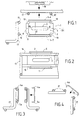
- the plate 1 shown in FIG. 1 comprises a central part 2 substantially planar provided with a central through hole 3 extending along a direction D1 called longitudinal.
- this central through hole is oblong. In other embodiments, this hole is not central and / or not oblong.
- This plate 1 when viewed in plan, is inscribed in an envelope rectangular and includes two longitudinal edges 4,5 on each of which protrudes a snap edge 6.7.
- the plate 1 comprises two edges transverse 8.9 each provided with two lateral grooves 10.11 extending at the corners of the plate 1.
- the transverse distance dt between the longitudinal edges 6,7 is substantially equal to a distance D separating two wires from the cable tray.
- These threads can be for example two closest chain threads neighbors, as shown in Figure 2, the plate 1 being snapped on these chain wires 14.15.
- these wafer support wires can, in variant, being two weft threads of the cable tray, these weft threads being neighbors or separated by one or more of a weft thread.
- the chain son on which is mounted the wafer 1 can be separated by one or more warp threads.
- the plate 1 can thus be mounted by snap-fastening, according to a first latching direction, between two warp or weft threads, on a wing, an intermediate wall or the bottom wall of a cable tray in wire mesh.
- the transverse latching can be provided with clamping or be of the type sliding in the longitudinal direction D1.
- the transverse latching can be carried out on the external face of the path to cables, as shown in Figure 1, or on the inside.
- the four grooves 10-13 formed at the corners of the plate 1 have complementary curvatures to the profiles of the chain or frame. It is thus possible, as shown in Figure 1, to snap the plate 1, in a longitudinal direction, on two son of chain or frame.
- the plate 1 can be provided, as shown in Figure 1, with minus a through hole 16 on its longitudinal edges.
- this through hole 16 allows the passage of a splint, made in a loop of wire or in the form of a flat.
- the plate is provided of two opposite holes passing through, on each of its longitudinal edges 4.5, a splint that can be inserted into either of these holes, or even at across both.
- the plate 1 can thus be used for guiding in sliding and / or holding in position of mounting plates.
- the wafer 1 is snapped onto the chain son of a cable tray wing, these chain wires being arranged outside by compared to the weft threads. It is understood, however, that mounting on the face external or internal of the wafer could be made on the chain wires mounted inside with respect to the weft threads.
- the plate shown in Figure 3 is provided with edges longitudinal 4a, 5a curves, following the curvature of the wires of the trellis.
- the longitudinal edges 4a, 5a can be provided with projections increasing the clamping force during latching.
- FIG. 4 the use of a plate such as shown in Figure 3 for the articulation of two sections of paths to wire mesh cables.
- the two longitudinal edges 4a, 5a of the wafer 1 are placed against the weft son 17 of two successive sections.
- the plate 1 according to the invention can be snapped in according to a transverse direction and / or a longitudinal direction, and thus allows the mounting of various accessories, or the guide of fishplates, on a path wire mesh cables with rectangular mesh.
- the plate can also be snapped between two mesh sections of cable trays arranged side by side, substantially parallel between them or not.
Landscapes
- Engineering & Computer Science (AREA)
- Architecture (AREA)
- Civil Engineering (AREA)
- Structural Engineering (AREA)
- Details Of Indoor Wiring (AREA)
- Installation Of Indoor Wiring (AREA)
- Clamps And Clips (AREA)
- Electric Cable Arrangement Between Relatively Moving Parts (AREA)
- Laying Of Electric Cables Or Lines Outside (AREA)
- Insertion, Bundling And Securing Of Wires For Electric Apparatuses (AREA)
- Pretreatment Of Seeds And Plants (AREA)
- Pit Excavations, Shoring, Fill Or Stabilisation Of Slopes (AREA)
Abstract
Description
- elle est de forme sensiblement rectangulaire, deux bords longitudinaux de la plaquette permettant un encliquetage de celle-ci sur deux fils distants d'une première valeur, la plaquette comprenant deux bords transversaux permettant un encliquetage de celle-ci sur deux fils distants d'une deuxième valeur, inférieure ou égale à la première ;
- ses bords longitudinaux ou ses bords transversaux présentent une courbure complémentaire au profil des fils du chemin à câbles ;
- elle comprend une partie centrale sensiblement plane pourvue d'un trou traversant, par exemple, oblong ;
- elle comprend deux bords longitudinaux en saillie et deux bords transversaux pourvus de gorges d'encliquetage, disposées aux angles de la plaquette.
- la figure 1 est une vue en plan d'une plaquette selon un mode de réalisation de l'invention, le principe de montage de cette plaquette sur les fils de chaíne ou les fils de trame d'un chemin à câbles étant schématisé ;
- la figure 2 est une vue d'une aile de chemin à câble en treillis de fils sur laquelle est encliquetée une plaquette telle que représentée en figure 1 ;
- la figure 3 est une vue en coupe de deux chemins à câbles en treillis de fils sur lesquels sont encliquetées des plaquettes en face externe (figure 3 gauche) ou interne (figure 3 droite) d'une aile ;
- la figure 4 est un schéma de principe de l'emploi d'une plaquette selon l'invention pour le raccordement de deux chemins à câbles.
- entre fils immédiatement voisins ou entre deux fils séparés par un plus d'un fil ;
- sur fils de chaíne ou fils de trame, en face interne ou en face externe du chemin à câble;
- avec ou sans possibilité de coulissement de la plaquette, en fonction de la force de serrage issu de l'encliquetage, cette force étant fonction notamment des rapports entre la distance dg entre gorges et l'écartement des fils supports, et étant fonction également de la rigidité des fils et de la plaquette, ces variables pouvant être ajustées par un homme du métier.
Claims (10)
- Plaquette encliquetable sur chemin à câbles en treillis de fils à maille rectangulaire, caractérisée en ce qu'elle comprend des moyens permettant son encliquetage sur les fils du chemin à câbles suivant deux directions sensiblement perpendiculaires.
- Plaquette suivant la revendication 1, caractérisée en ce qu'elle est de forme sensiblement rectangulaire, deux bords longitudinaux (4,5) de la plaquette permettant un encliquetage de celle-ci sur deux fils distants d'une première valeur, la plaquette comprenant deux bords transversaux (8,9) permettant un encliquetage de celle-ci sur deux fils distants d'une deuxième valeur, inférieure ou égale à la première.
- Plaquette suivant la revendication 2, caractérisée en ce que ses bords longitudinaux (4,5) ou ses bords transversaux (8,9) présentent une courbure complémentaire au profil des fils du chemin à câbles.
- Plaquette suivant l'une quelconque des revendications 1 à 3, caractérisé en en ce qu'elle comprend une partie centrale (2) sensiblement plane pourvue d'un trou traversant (3).
- Plaquette suivant l'une quelconque des revendications 1 à 4, caractérisé en ce qu'elle comprend deux bords longitudinaux en saillie et deux bords transversaux pourvus de gorges d'encliquetage (10-13), disposées aux angles de la plaquette.
- Montage d'une plaquette telle que présentée dans l'une quelconque des revendications 1 à 5 sur un chemin à câbles en treillis de fils, caractérisé en ce que l'encliquetage de la plaquette est obtenu, pour au moins une des directions d'encliquetage, par écartement de deux fils du chemin à câbles par introduction de la plaquette entre ces deux fils.
- Montage d'une plaquette telle que présentée dans l'une quelconque des revendications 1 à 5 sur un chemin à câbles en treillis de fils, caractérisé en ce que l'encliquetage de la plaquette est obtenu, pour au moins une des directions d'encliquetage, par rapprochement de deux fils du chemin à câbles, enserrés entre deux bords opposés de la plaquette.
- Montage d'une plaquette suivant la revendication 6 ou 7, caractérisé en ce que l'encliquetage de la plaquette est coulissant suivant au moins une des directions d'encliquetage.
- Montage d'une plaquette suivant la revendication 6 ou 7, caractérisé en ce que la plaquette est encliquetée sur deux fils de trames de tronçons contigus, formant ainsi articulation entre ces deux tronçons.
- Montage d'une plaquette suivant la revendication 6 ou 7, caractérisé en ce que la plaquette est encliquetée entre deux mailles de tronçons de chemins à câbles disposés côte à côte.
Applications Claiming Priority (2)
| Application Number | Priority Date | Filing Date | Title |
|---|---|---|---|
| FR0012838A FR2815184B1 (fr) | 2000-10-06 | 2000-10-06 | Plaquettes encliquetables pour chemins a cables en treillis de fils, montage de telles plaquettes sur des chemins a cables |
| FR0012838 | 2000-10-06 |
Publications (2)
| Publication Number | Publication Date |
|---|---|
| EP1195870A1 true EP1195870A1 (fr) | 2002-04-10 |
| EP1195870B1 EP1195870B1 (fr) | 2003-03-12 |
Family
ID=8855106
Family Applications (1)
| Application Number | Title | Priority Date | Filing Date |
|---|---|---|---|
| EP01490029A Expired - Lifetime EP1195870B1 (fr) | 2000-10-06 | 2001-08-16 | Plaquettes encliquetables pour chemins à câbles en treillis de fils, montage de telles plaquettes sur des chemins à câbles |
Country Status (7)
| Country | Link |
|---|---|
| EP (1) | EP1195870B1 (fr) |
| AT (1) | ATE234523T1 (fr) |
| DE (1) | DE60100122T2 (fr) |
| DK (1) | DK1195870T3 (fr) |
| ES (1) | ES2194825T3 (fr) |
| FR (1) | FR2815184B1 (fr) |
| PT (1) | PT1195870E (fr) |
Cited By (5)
| Publication number | Priority date | Publication date | Assignee | Title |
|---|---|---|---|---|
| GB2467426A (en) * | 2009-01-30 | 2010-08-04 | Schneider Electric Espana Sa | Joining device for grid trays |
| WO2012168655A1 (fr) * | 2011-06-07 | 2012-12-13 | Legrand France | Accessoire d'angle pour chemins de cables en fils |
| WO2012168644A1 (fr) * | 2011-06-07 | 2012-12-13 | Legrand France | Accessoire d'angle pour chemins de cables en fils |
| US9178343B2 (en) | 2010-05-19 | 2015-11-03 | Panduit Corp. | Cable tray cable routing system |
| US9293899B2 (en) | 2013-02-12 | 2016-03-22 | Panduit Corp. | Transition splice for cable routing system |
Families Citing this family (2)
| Publication number | Priority date | Publication date | Assignee | Title |
|---|---|---|---|---|
| ES2362251B1 (es) * | 2010-12-27 | 2012-04-25 | Schneider Electric España, S.A | Accesorio de fijación para tabiques separadores en bandejas portacables de canalizaciones eléctricas. |
| US11677221B2 (en) | 2020-10-22 | 2023-06-13 | Panduit Corp. | Locking snap-on splice for cable basket |
Citations (3)
| Publication number | Priority date | Publication date | Assignee | Title |
|---|---|---|---|---|
| EP0355081A2 (fr) * | 1988-08-17 | 1990-02-21 | Lanz Oensingen Ag | Canalisation d'installation de câbles |
| FR2766897A1 (fr) * | 1997-08-01 | 1999-02-05 | Metal Deploye Sa | Chemin de cables en fils equipe d'au moins un accessoire de fixation, et accessoire de fixation correspondant |
| EP0905843A2 (fr) * | 1997-09-24 | 1999-03-31 | OBO Bettermann GmbH & Co. KG. | Dispositif d'attache sans vis pour canalisations de cables en treillis |
-
2000
- 2000-10-06 FR FR0012838A patent/FR2815184B1/fr not_active Expired - Fee Related
-
2001
- 2001-08-16 DE DE60100122T patent/DE60100122T2/de not_active Expired - Lifetime
- 2001-08-16 DK DK01490029T patent/DK1195870T3/da active
- 2001-08-16 PT PT01490029T patent/PT1195870E/pt unknown
- 2001-08-16 EP EP01490029A patent/EP1195870B1/fr not_active Expired - Lifetime
- 2001-08-16 AT AT01490029T patent/ATE234523T1/de not_active IP Right Cessation
- 2001-08-16 ES ES01490029T patent/ES2194825T3/es not_active Expired - Lifetime
Patent Citations (4)
| Publication number | Priority date | Publication date | Assignee | Title |
|---|---|---|---|---|
| EP0355081A2 (fr) * | 1988-08-17 | 1990-02-21 | Lanz Oensingen Ag | Canalisation d'installation de câbles |
| US5062605A (en) * | 1988-08-17 | 1991-11-05 | Lanz Oensingen Ag | Cable-laying conduit |
| FR2766897A1 (fr) * | 1997-08-01 | 1999-02-05 | Metal Deploye Sa | Chemin de cables en fils equipe d'au moins un accessoire de fixation, et accessoire de fixation correspondant |
| EP0905843A2 (fr) * | 1997-09-24 | 1999-03-31 | OBO Bettermann GmbH & Co. KG. | Dispositif d'attache sans vis pour canalisations de cables en treillis |
Cited By (14)
| Publication number | Priority date | Publication date | Assignee | Title |
|---|---|---|---|---|
| GB2467426B (en) * | 2009-01-30 | 2013-04-10 | Schneider Electric Espaa A S A | Joining device for grid trays and section of grid trays joined by means of said device |
| GB2467426A (en) * | 2009-01-30 | 2010-08-04 | Schneider Electric Espana Sa | Joining device for grid trays |
| US11056865B2 (en) | 2010-05-19 | 2021-07-06 | Panduit Corp. | Cable tray cable routing system |
| US9853428B2 (en) | 2010-05-19 | 2017-12-26 | Panduit Corp. | Cable tray cable routing system |
| US9178343B2 (en) | 2010-05-19 | 2015-11-03 | Panduit Corp. | Cable tray cable routing system |
| CN103563195A (zh) * | 2011-06-07 | 2014-02-05 | 罗格朗法国公司 | 用于线型缆道的角度附件 |
| FR2976334A1 (fr) * | 2011-06-07 | 2012-12-14 | Legrand France | Accessoire d'angle pour chemins de cables en fils |
| CN103563196A (zh) * | 2011-06-07 | 2014-02-05 | 罗格朗法国公司 | 用于线状缆索道的角配件 |
| FR2976335A1 (fr) * | 2011-06-07 | 2012-12-14 | Legrand France | Accessoire d'angle pour chemins de cables en fils |
| CN103563195B (zh) * | 2011-06-07 | 2016-04-27 | 罗格朗法国公司 | 用于线型缆道的角度附件 |
| CN103563196B (zh) * | 2011-06-07 | 2016-05-11 | 罗格朗法国公司 | 用于线状缆索道的角配件 |
| WO2012168644A1 (fr) * | 2011-06-07 | 2012-12-13 | Legrand France | Accessoire d'angle pour chemins de cables en fils |
| WO2012168655A1 (fr) * | 2011-06-07 | 2012-12-13 | Legrand France | Accessoire d'angle pour chemins de cables en fils |
| US9293899B2 (en) | 2013-02-12 | 2016-03-22 | Panduit Corp. | Transition splice for cable routing system |
Also Published As
| Publication number | Publication date |
|---|---|
| EP1195870B1 (fr) | 2003-03-12 |
| FR2815184B1 (fr) | 2003-03-28 |
| DK1195870T3 (da) | 2003-06-23 |
| DE60100122D1 (de) | 2003-04-17 |
| ATE234523T1 (de) | 2003-03-15 |
| ES2194825T3 (es) | 2003-12-01 |
| DE60100122T2 (de) | 2003-12-04 |
| FR2815184A1 (fr) | 2002-04-12 |
| PT1195870E (pt) | 2003-07-31 |
Similar Documents
| Publication | Publication Date | Title |
|---|---|---|
| EP2115837B1 (fr) | Dispositif de fixation pour chemin de cables en fils | |
| EP0718944B1 (fr) | Chemin de câbles en fils | |
| EP1192693A1 (fr) | Accessoire de fixation pour chemin de cables en fils, et chemin de cables en fils equipe au moins d'un tel accessoire | |
| FR2612539A1 (fr) | Poutrelle de support de plafond | |
| FR3002967A3 (fr) | Ensemble de porte de douche | |
| EP1195870B1 (fr) | Plaquettes encliquetables pour chemins à câbles en treillis de fils, montage de telles plaquettes sur des chemins à câbles | |
| EP1306502B1 (fr) | Clôture | |
| EP1249908B1 (fr) | Ensemble de montage de connecteur électrique | |
| EP0974706B1 (fr) | Dispositif de cloison amovible | |
| FR2672741A1 (fr) | Armoire electrique avec un bati et un socle. | |
| FR3029022A1 (fr) | Support reversible pour chemin de cables | |
| US6053779A (en) | Terminal clamp and electrical wire mounting arrangement | |
| EP1193820B1 (fr) | Support d'accessoires pour chemins à câbles et chemins à câbles comprenant de tels supports | |
| EP1775399B1 (fr) | Revêtement de facade | |
| EP1150407B1 (fr) | Troncon de chemin à câbles en treillis de fils et chemin à câbles obtenu par assemblage d'au moins deux des dits troncons | |
| FR2566222A1 (fr) | Assemblage en triedre | |
| FR2738445A1 (fr) | Accessoire de support pour l'assujettissement d'un barreau a un autre element de chassis, notamment pour le support d'appareils electriques | |
| GB2405900A (en) | Cable clamps | |
| FR2838569A1 (fr) | Attache de maintien de couvercle pour chemins de cables | |
| EP1557502B1 (fr) | Elément de solidarisation réversible, panneaux et rangements mettant en oeuvre de tels éléments | |
| FR2753228A1 (fr) | Profil de jonction et de coupure thermique interpose entre des profiles aluminium utilises notamment dans la confection des cadres de fenetres ou de portes | |
| JPH0754540Y2 (ja) | 目隠し用部材 | |
| FR2680552A1 (fr) | Dispositif d'assemblage pour une serre ou un hangar. | |
| FR3143224A1 (fr) | Chemin de câbles d’interconnexion flexible. | |
| FR2701607A1 (fr) | Fond d'armoire, et armoire, en particulier armoire électrique, équipée à sa partie basse d'un tel fond. |
Legal Events
| Date | Code | Title | Description |
|---|---|---|---|
| PUAI | Public reference made under article 153(3) epc to a published international application that has entered the european phase |
Free format text: ORIGINAL CODE: 0009012 |
|
| AK | Designated contracting states |
Kind code of ref document: A1 Designated state(s): AT BE CH CY DE DK ES FI FR GB GR IE IT LI LU MC NL PT SE TR |
|
| AX | Request for extension of the european patent |
Free format text: AL;LT;LV;MK;RO;SI |
|
| 17P | Request for examination filed |
Effective date: 20020201 |
|
| GRAH | Despatch of communication of intention to grant a patent |
Free format text: ORIGINAL CODE: EPIDOS IGRA |
|
| GRAH | Despatch of communication of intention to grant a patent |
Free format text: ORIGINAL CODE: EPIDOS IGRA |
|
| AKX | Designation fees paid |
Free format text: AT BE CH CY DE DK ES FI FR GB GR IE IT LI LU MC NL PT SE TR |
|
| GRAA | (expected) grant |
Free format text: ORIGINAL CODE: 0009210 |
|
| AK | Designated contracting states |
Designated state(s): AT BE CH CY DE DK ES FI FR GB GR IE IT LI LU MC NL PT SE TR |
|
| PG25 | Lapsed in a contracting state [announced via postgrant information from national office to epo] |
Ref country code: TR Free format text: LAPSE BECAUSE OF FAILURE TO SUBMIT A TRANSLATION OF THE DESCRIPTION OR TO PAY THE FEE WITHIN THE PRESCRIBED TIME-LIMIT Effective date: 20030312 Ref country code: GR Free format text: LAPSE BECAUSE OF FAILURE TO SUBMIT A TRANSLATION OF THE DESCRIPTION OR TO PAY THE FEE WITHIN THE PRESCRIBED TIME-LIMIT Effective date: 20030312 |
|
| REG | Reference to a national code |
Ref country code: GB Ref legal event code: FG4D Free format text: NOT ENGLISH |
|
| REG | Reference to a national code |
Ref country code: CH Ref legal event code: EP |
|
| REG | Reference to a national code |
Ref country code: CH Ref legal event code: NV Representative=s name: BOVARD AG PATENTANWAELTE |
|
| REG | Reference to a national code |
Ref country code: IE Ref legal event code: FG4D Free format text: FRENCH |
|
| REF | Corresponds to: |
Ref document number: 60100122 Country of ref document: DE Date of ref document: 20030417 Kind code of ref document: P |
|
| REG | Reference to a national code |
Ref country code: SE Ref legal event code: TRGR |
|
| GBT | Gb: translation of ep patent filed (gb section 77(6)(a)/1977) |
Effective date: 20030507 |
|
| REG | Reference to a national code |
Ref country code: DK Ref legal event code: T3 |
|
| PG25 | Lapsed in a contracting state [announced via postgrant information from national office to epo] |
Ref country code: LU Free format text: LAPSE BECAUSE OF NON-PAYMENT OF DUE FEES Effective date: 20030816 Ref country code: CY Free format text: LAPSE BECAUSE OF FAILURE TO SUBMIT A TRANSLATION OF THE DESCRIPTION OR TO PAY THE FEE WITHIN THE PRESCRIBED TIME-LIMIT Effective date: 20030816 |
|
| PG25 | Lapsed in a contracting state [announced via postgrant information from national office to epo] |
Ref country code: MC Free format text: LAPSE BECAUSE OF NON-PAYMENT OF DUE FEES Effective date: 20030831 |
|
| PLBE | No opposition filed within time limit |
Free format text: ORIGINAL CODE: 0009261 |
|
| STAA | Information on the status of an ep patent application or granted ep patent |
Free format text: STATUS: NO OPPOSITION FILED WITHIN TIME LIMIT |
|
| 26N | No opposition filed |
Effective date: 20031215 |
|
| PGFP | Annual fee paid to national office [announced via postgrant information from national office to epo] |
Ref country code: SE Payment date: 20040715 Year of fee payment: 4 |
|
| PGFP | Annual fee paid to national office [announced via postgrant information from national office to epo] |
Ref country code: AT Payment date: 20040716 Year of fee payment: 4 |
|
| PGFP | Annual fee paid to national office [announced via postgrant information from national office to epo] |
Ref country code: FI Payment date: 20040723 Year of fee payment: 4 |
|
| PGFP | Annual fee paid to national office [announced via postgrant information from national office to epo] |
Ref country code: DK Payment date: 20040803 Year of fee payment: 4 |
|
| PGFP | Annual fee paid to national office [announced via postgrant information from national office to epo] |
Ref country code: PT Payment date: 20040817 Year of fee payment: 4 |
|
| PG25 | Lapsed in a contracting state [announced via postgrant information from national office to epo] |
Ref country code: AT Free format text: LAPSE BECAUSE OF NON-PAYMENT OF DUE FEES Effective date: 20050816 Ref country code: FI Free format text: LAPSE BECAUSE OF NON-PAYMENT OF DUE FEES Effective date: 20050816 |
|
| PG25 | Lapsed in a contracting state [announced via postgrant information from national office to epo] |
Ref country code: SE Free format text: LAPSE BECAUSE OF NON-PAYMENT OF DUE FEES Effective date: 20050817 |
|
| PG25 | Lapsed in a contracting state [announced via postgrant information from national office to epo] |
Ref country code: CH Free format text: LAPSE BECAUSE OF NON-PAYMENT OF DUE FEES Effective date: 20050831 Ref country code: DK Free format text: LAPSE BECAUSE OF NON-PAYMENT OF DUE FEES Effective date: 20050831 Ref country code: LI Free format text: LAPSE BECAUSE OF NON-PAYMENT OF DUE FEES Effective date: 20050831 |
|
| PG25 | Lapsed in a contracting state [announced via postgrant information from national office to epo] |
Ref country code: PT Free format text: LAPSE BECAUSE OF NON-PAYMENT OF DUE FEES Effective date: 20060216 |
|
| REG | Reference to a national code |
Ref country code: CH Ref legal event code: PL |
|
| REG | Reference to a national code |
Ref country code: DK Ref legal event code: EBP |
|
| EUG | Se: european patent has lapsed | ||
| REG | Reference to a national code |
Ref country code: FR Ref legal event code: TP |
|
| REG | Reference to a national code |
Ref country code: GB Ref legal event code: 732E Free format text: REGISTERED BETWEEN 20110505 AND 20110511 |
|
| REG | Reference to a national code |
Ref country code: NL Ref legal event code: TD Effective date: 20110701 Ref country code: NL Ref legal event code: SD Effective date: 20110701 |
|
| BECA | Be: change of holder's address |
Owner name: CTS CABLE TRAY SYSTEMS SAS186 AVENUE DE LA FERME D Effective date: 20110706 |
|
| BECN | Be: change of holder's name |
Owner name: CTS CABLE TRAY SYSTEMS SAS Effective date: 20110706 |
|
| REG | Reference to a national code |
Ref country code: DE Ref legal event code: R082 Ref document number: 60100122 Country of ref document: DE Representative=s name: PATENTANWAELTE HEYERHOFF & GEIGER, DE |
|
| REG | Reference to a national code |
Ref country code: ES Ref legal event code: PC2A Owner name: CTS CABLE TRAY SYSTEMS SAS Effective date: 20111103 |
|
| REG | Reference to a national code |
Ref country code: DE Ref legal event code: R081 Ref document number: 60100122 Country of ref document: DE Owner name: CTS CABLE TRAY SYSTEMS SAS - CTS, FR Free format text: FORMER OWNER: TOLMEGA, S.A., BETHUNE, FR Effective date: 20111007 Ref country code: DE Ref legal event code: R082 Ref document number: 60100122 Country of ref document: DE Representative=s name: HEYERHOFF GEIGER & PARTNER PATENTANWAELTE, DE Effective date: 20111007 Ref country code: DE Ref legal event code: R082 Ref document number: 60100122 Country of ref document: DE Representative=s name: HEYERHOFF GEIGER & PARTNER PATENTANWAELTE PART, DE Effective date: 20111007 Ref country code: DE Ref legal event code: R081 Ref document number: 60100122 Country of ref document: DE Owner name: NIEDAX FRANCE, FR Free format text: FORMER OWNER: TOLMEGA, S.A., BETHUNE, FR Effective date: 20111007 |
|
| PGFP | Annual fee paid to national office [announced via postgrant information from national office to epo] |
Ref country code: IE Payment date: 20140723 Year of fee payment: 14 Ref country code: NL Payment date: 20140721 Year of fee payment: 14 |
|
| PGFP | Annual fee paid to national office [announced via postgrant information from national office to epo] |
Ref country code: GB Payment date: 20140725 Year of fee payment: 14 |
|
| PGFP | Annual fee paid to national office [announced via postgrant information from national office to epo] |
Ref country code: IT Payment date: 20140729 Year of fee payment: 14 |
|
| REG | Reference to a national code |
Ref country code: FR Ref legal event code: PLFP Year of fee payment: 15 |
|
| GBPC | Gb: european patent ceased through non-payment of renewal fee |
Effective date: 20150816 |
|
| PG25 | Lapsed in a contracting state [announced via postgrant information from national office to epo] |
Ref country code: IT Free format text: LAPSE BECAUSE OF NON-PAYMENT OF DUE FEES Effective date: 20150816 |
|
| REG | Reference to a national code |
Ref country code: NL Ref legal event code: MM Effective date: 20150901 |
|
| REG | Reference to a national code |
Ref country code: IE Ref legal event code: MM4A |
|
| PG25 | Lapsed in a contracting state [announced via postgrant information from national office to epo] |
Ref country code: NL Free format text: LAPSE BECAUSE OF NON-PAYMENT OF DUE FEES Effective date: 20150901 |
|
| REG | Reference to a national code |
Ref country code: DE Ref legal event code: R082 Ref document number: 60100122 Country of ref document: DE Representative=s name: HEYERHOFF GEIGER & PARTNER PATENTANWAELTE PART, DE Ref country code: FR Ref legal event code: PLFP Year of fee payment: 16 Ref country code: DE Ref legal event code: R081 Ref document number: 60100122 Country of ref document: DE Owner name: NIEDAX FRANCE, FR Free format text: FORMER OWNER: CTS CABLE TRAY SYSTEMS SAS - CTS, BETHUNE, FR |
|
| PG25 | Lapsed in a contracting state [announced via postgrant information from national office to epo] |
Ref country code: GB Free format text: LAPSE BECAUSE OF NON-PAYMENT OF DUE FEES Effective date: 20150816 Ref country code: IE Free format text: LAPSE BECAUSE OF NON-PAYMENT OF DUE FEES Effective date: 20150816 |
|
| REG | Reference to a national code |
Ref country code: ES Ref legal event code: PC2A Owner name: NIEDAX FRANCE Effective date: 20160804 |
|
| REG | Reference to a national code |
Ref country code: FR Ref legal event code: PLFP Year of fee payment: 17 |
|
| PGFP | Annual fee paid to national office [announced via postgrant information from national office to epo] |
Ref country code: ES Payment date: 20170904 Year of fee payment: 17 Ref country code: DE Payment date: 20170719 Year of fee payment: 17 Ref country code: FR Payment date: 20170801 Year of fee payment: 17 |
|
| PGFP | Annual fee paid to national office [announced via postgrant information from national office to epo] |
Ref country code: BE Payment date: 20170721 Year of fee payment: 17 |
|
| REG | Reference to a national code |
Ref country code: DE Ref legal event code: R119 Ref document number: 60100122 Country of ref document: DE |
|
| REG | Reference to a national code |
Ref country code: BE Ref legal event code: HC Owner name: NIEDAX FRANCE; FR Free format text: DETAILS ASSIGNMENT: CHANGE OF OWNER(S), CHANGEMENT NOM PROPRIETAIRE; FORMER OWNER NAME: CTS CABLE TRAY SYSTEMS SAS Effective date: 20160718 Ref country code: BE Ref legal event code: MM Effective date: 20180831 |
|
| PG25 | Lapsed in a contracting state [announced via postgrant information from national office to epo] |
Ref country code: DE Free format text: LAPSE BECAUSE OF NON-PAYMENT OF DUE FEES Effective date: 20190301 |
|
| PG25 | Lapsed in a contracting state [announced via postgrant information from national office to epo] |
Ref country code: FR Free format text: LAPSE BECAUSE OF NON-PAYMENT OF DUE FEES Effective date: 20180831 Ref country code: BE Free format text: LAPSE BECAUSE OF NON-PAYMENT OF DUE FEES Effective date: 20180831 |
|
| REG | Reference to a national code |
Ref country code: ES Ref legal event code: FD2A Effective date: 20190918 |
|
| PG25 | Lapsed in a contracting state [announced via postgrant information from national office to epo] |
Ref country code: ES Free format text: LAPSE BECAUSE OF NON-PAYMENT OF DUE FEES Effective date: 20180817 |