EP1195868A2 - Haltevorrichtung für Frontabdeckungen von Elektroinstallationen - Google Patents
Haltevorrichtung für Frontabdeckungen von Elektroinstallationen Download PDFInfo
- Publication number
- EP1195868A2 EP1195868A2 EP01123652A EP01123652A EP1195868A2 EP 1195868 A2 EP1195868 A2 EP 1195868A2 EP 01123652 A EP01123652 A EP 01123652A EP 01123652 A EP01123652 A EP 01123652A EP 1195868 A2 EP1195868 A2 EP 1195868A2
- Authority
- EP
- European Patent Office
- Prior art keywords
- support
- holding device
- carrier
- tower
- towers
- Prior art date
- Legal status (The legal status is an assumption and is not a legal conclusion. Google has not performed a legal analysis and makes no representation as to the accuracy of the status listed.)
- Granted
Links
Images



Classifications
-
- H—ELECTRICITY
- H02—GENERATION; CONVERSION OR DISTRIBUTION OF ELECTRIC POWER
- H02B—BOARDS, SUBSTATIONS OR SWITCHING ARRANGEMENTS FOR THE SUPPLY OR DISTRIBUTION OF ELECTRIC POWER
- H02B1/00—Frameworks, boards, panels, desks, casings; Details of substations or switching arrangements
- H02B1/26—Casings; Parts thereof or accessories therefor
- H02B1/46—Boxes; Parts thereof or accessories therefor
- H02B1/48—Mounting of devices therein
-
- H—ELECTRICITY
- H02—GENERATION; CONVERSION OR DISTRIBUTION OF ELECTRIC POWER
- H02B—BOARDS, SUBSTATIONS OR SWITCHING ARRANGEMENTS FOR THE SUPPLY OR DISTRIBUTION OF ELECTRIC POWER
- H02B1/00—Frameworks, boards, panels, desks, casings; Details of substations or switching arrangements
- H02B1/015—Boards, panels, desks; Parts thereof or accessories therefor
- H02B1/04—Mounting thereon of switches or of other devices in general, the switch or device having, or being without, casing
- H02B1/052—Mounting on rails
Definitions
- the invention relates to a holding device for front covers of electrical installations, in particular power distribution systems, with support towers protruding from a support base as a holder for the front cover.
- carrier towers e.g. to use in distribution boxes where they are perpendicular from protrude along the rear wall of the box support rails, which are a support base among other things, form for the towers.
- the ends of the carrier towers have devices for fastening the front cover, e.g. Plug-in openings for a fastening bolt.
- a carrier base also come with the mentioned support rails longitudinally connectable foot rails of a module for installation into a distribution box of a power distribution system into consideration, the foot rails spaced parallel to one another and via crossbeam devices, e.g. DIN rails, are interconnected.
- Four carrier towers are then each on the Ends of the foot rails arranged, the front ends of which are rectangular with the corners Front cover for the module can be connected.
- the carrier towers extend almost over the entire depth of the power distribution system, where to carry out installation work, in particular the laying and the Connection of cables, hinder. On the other hand, if the Carrier towers on the support rails or foot rails cause considerable difficulties, to keep the space required for the carrier towers free during the laying of cables.
- the present invention has for its object a new holding device for To create front covers of electrical installations of the type mentioned, which assembly work to be carried out on electrical installations, in particular power distribution systems facilitated.
- the holding device according to the invention which achieves this object is characterized in that that the carrier towers can be assembled from several parts.
- the support base Part of the carrier tower when installing a power distribution system early, preferably already installed at the factory.
- this part of the tower is not over the entire height or depth of the power distribution system, it interferes with subsequent assembly and wiring work not.
- the one required for the carrier towers Space reserved. After completion of this work, the already assembled part of the tower forms a seat ensuring the exact positioning of a further part of the support tower after completion of the assembly and wiring work, the carrier tower with little Workload can be comfortably completed, e.g. making a connector between the girder tower parts.
- the support tower part adjoining the support base can be made in one piece with a support rail connected as a support base, preferably a foot rail of the above-mentioned module his.
- the carrier tower parts can preferably be detachably joined together to form the carrier tower connect. During repair or supplementary work on a power distribution system thus created space by removing the support tower parts facing the fitter become.
- the above-mentioned plug connection between the support tower parts can preferably be snapped into place, so that the risk of unintentional detachment of carrier tower parts is eliminated.
- a plug connection can be produced between the support base and the support tower part adjoining the support base, for example in such a way that this support tower part can be plugged onto the support rail in the longitudinal direction of the rail, for which purpose it has, for example, a foot with a through opening adapted to the profile of the support rail can.
- a screw connection between the relevant tower part and the carrier rail is expediently used to lock the relevant tower part in the longitudinal direction of the rail.
- the support tower part adjoining the support base can be provided with devices for a snap fastening on the support base or on a housing which accommodates the electrical installation. Accordingly, it is conceivable to connect the relevant support tower parts to the ends of support rails of a support frame arranged parallel and at a distance from one another, and to snap the support tower parts into the corner regions of a housing receiving the support frame.
- the support rails mentioned can, as already mentioned, foot rails one for installation be provided in a power distribution system module, with the support towers on protrude four corners of the module from the foot rails.
- the carrier towers within the Electrical installation in addition to its function as a holder of the front cover at least one further functions, preferably holding functions.
- Bracket side protection covers of a module or the brackets of a transparent protective screen especially to be placed over a busbar Consideration.
- interconnected double or Quadruple carrier towers for cross-module arrangement on adjoining Carrier bases of adjacent modules can be provided. That is, in power distribution systems, in which a large number of modules are installed, such double towers can be located at joints are placed between modules, e.g. a carrier tower of a double tower assigned a module and the other carrier tower of the double tower to the adjacent module is.
- kits can be used with each other in relation to their Establish connection compatible tower parts so that e.g. Carrier towers with different Overall heights and different additional functions can be put together.
- the different heights can result from prescribed standard grid dimensions, where e.g. Tower parts with the different standard formats of top-hat rails adjusted heights can be produced. This can be related to the number of additional functions that can be performed Despite the multi-part design of the carrier towers, such kits make them more compatible Carrier tower parts overall a reduction in the number of parts of power distribution systems to reach.
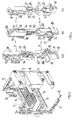
- the reference numerals 1 and 2 in FIG. 1 denote metal foot rails, as the basic parts of a module for installation in the housing of power distribution systems serve.
- the module can e.g. connected with support rails which are placed vertically along the rear wall of a junction box Run inside.
- the foot rails 1 and 2 are metallic Top hat rails 3 and 4 connected to each other.
- the top-hat rails 3 and 4 are on their ends screwed to the foot rails 1 and 2 and serve to accommodate Modular devices, e.g. Fuse switches.
- support towers 5 are attached to the foot rail 1 in the longitudinal direction of the rail, which in two parts with a foot part 6 and a plug-on part which can be plugged onto the foot part 7 are formed.
- the carrier towers 5 made of plastic are shown below 4 described in detail.
- FIG. 2 shows a module using the components described above, which contains carrier towers 5 only.
- the foot rail 1 is omitted in FIG. 2.
- a cover 8 with windows 9 is attached on the carrier forms 5, a cover 8 with windows 9 is attached.
- windows 9 Through the window 9 modular devices that can be attached to the support rails 3 and 4 are accessible from the outside.
- the omission of the foot rail 1 is intended to indicate that the support towers 5 of the Module not only via a foot rail but also directly on one with a distribution box connected carrier rail could be attached.
- FIG. 3 also shows a module for using the parts described above Installation in a distribution box in which the carrier towers 5 are used to hold the cover 8 are.
- the top-hat rails 3 and 4 with U-shaped bracket 10 with the foot rails 1 and 2 connected, the U-shaped bracket 10 to form cable guides serve in which cables are routed parallel to the foot rails.
- a further cable guide 11 is provided, in which cables are perpendicular to Let the foot rails run and out of the cable for connection to the top-hat rails 3 and 4 attached modular devices can be branched.
- Snap bolts 12 which are in a rotational position, can be used to fasten the cover 8 engage and in a position rotated by 90 ° with respect to this position have it detached from the catch.
- FIG. 4 where the support tower 5 is in three different perspective Views is shown.
- Foot part 6 has a mounting plate 13 with a bore 14 and two further bores 71 and 72 on.
- a plug-in foot 15 From one side of the plate extends a plug-in foot 15, in which an angled in cross section Passage 16 is formed. At 17, 18 non-continuous recesses are to be avoided of material accumulations provided in the plug-in foot 15.
- Plug-in sleeve 19 with a plug-in channel 50.
- the Plug-in sleeve and the plug-in channel are stepped, and the plug-in sleeve 19 has at 20 a snap opening for a nose.
- a gradation 22 of the socket 19 are one further locking opening 21 and a recess 38 are formed.
- diametrical corner of the socket 19 is a over the entire length of the socket 19th extending groove 23 is formed, which opens to the free end of the receptacle 19.
- the plug-in part 7 has a stepped plug-in shaft 24, which is hollow and provided with an opening 25 in the form of a longitudinal slot is which when inserting the plug part in the foot part with the opening 21 of the foot part to Cover comes.
- a U slot is provided at 26 through which one elastically movable locking lip 27 is formed.
- a locking lug 28 is provided for by the locking lip 27 the engagement in the locking opening 20 of the socket 19 before.
- One closes on the stem Tower extension 29 on, at its free end facing away from the plug shaft 24 Has slot 30 for the above-mentioned snap pin 12.
- the slot 30 opens inward to a cavity 51 open on opposite sides, in which forming a trough and a gap 52 extending along the trough line Project locking lips 31 for locking with the snap pin 12.
- the locking lips 31 contained cavity 51 closes a section with depressions 32 and 33, which serve to avoid material accumulation.
- Another section of the tower extension 29 has a continuous cross section rectangular plug hole 34 for a holding element that can be plugged onto the support tower, which 7 and 8 will be explained in more detail below.
- the plug hole 34 closes flush on one side with a longitudinal side wall of the tower extension 29 off while it is on the other side opposite the side wall in question the tower extension opens back into a cavity 53 open on one side, which is partly formed by the depression 32.
- a stop plate extends from the tower extension 29 below the plug hole 34 35, which is flush with the end of the tower extension 29, the formation a gradation 54 adjacent to the stem 24.
- a nose 36 which runs along a continuous longitudinal groove 55 and adjacent to a recess 37 which in the between the tower extension 29 and the Plug shaft 24 formed gradation 54 is formed.
- the foot parts 6 of the support towers 5 are open attach the ends of the foot rails 1 and 2, the foot rails in the angled Plug-in channel 16 of the plug-in feet 15 of the foot parts 6 are introduced.
- Using the Bore 14 can then be a fixation of the support tower on the foot rail by a Screw connection between support tower and foot rail.
- the holes 71 and 72 part of the mounting plate 13 is opposite to the rest of this Plate reinforced by the material thickness of the foot rail. Over this reinforced part of the mounting plate 13 can, as explained above with reference to FIG. 2, the support tower directly be attached to a support rail, the tower height being maintained by the reinforcement remains.
- This insertion of the plug-in parts may only be possible during installation work on site after the assembly of modular devices and their connection wiring take place, then finally the front cover 8 by means of the locking pin 12 the towers 5 is attached.
- the grooves 23 can face each other Various foot rails attached foot parts 6 can be used to lateral Push protective covers, which then with the insertion of the plug-in parts 7 in the Foot parts 6 are fixed.
- the openings are also used to fix additional side protective covers 21 and 25 and the recess 38 can be used, which lugs such lateral Can accommodate protective covers.
- additional side protective covers can the nose 36, the groove 55 and the recess 57 on the tower extension 29 can be used.
- the module's foot rails may include a busbar support member 70, such as 7 and 8, can be inserted.
- the holding element 70 has a plug-in channel which is open on one end face and one long side 39, in which a locking opening 40 for the engagement of a locking lug 40 one in the plug-in channel 39 insertable plug element is provided.
- a plug-in channel 39 Opposite the open face the plug-in channel 39 is delimited by an end plate 41, to which a plate-shaped Connect approach 42 and a hollow cylindrical approach 43, the hollow cylindrical Approach 43 is connected via a web with the plate-shaped extension 42 and the latter Cylinder axis extends in the longitudinal direction of the plug-in channel 39.
- plug-in lug 44 for insertion into the above hole 34 before.
- the hollow pin 44 has slots 45 through which opposite sides of the nose 44 elastically bendable locking lips 46 with a Latch 47 are formed.
- the tab 44 is inclusive at its front end in the direction of insertion the locking lips 46 beveled to facilitate insertion into the plug hole 34.
- This carrier tower has a foot part 6a and a plug part 7a, the foot part 6a with corresponds to the base part 6 of the carrier tower 5 and cannot be explained further here.
- plug-in part 7a In contrast to the plug-in part 7 of the carrier tower 5, one is essential on the plug-in part 7a shorter tower extension 29a with a plug hole 30a and locking lips 31a in one two sides open cavity 51a of the plug part 7a is formed.
- a plug-in shaft 24a connects, which in Difference to the plug shaft 24 of the tower extension 29 is not stepped, but one has rectangular cross section.
- Through longitudinal slots 49 is an elastically bendable Locking lip 27a formed with a locking lug 28a.
- the nose 28a engages when the plug-in part 7a is inserted into the Foot part 6a into a latching opening 21a on a plug-in sleeve 19a.
- FIG. 6 in the partial figures a and b of which a further exemplary embodiment for a carrier tower is shown in two different perspective views.
- the carrier tower has a base part 6b and a plug-in part 7b, the plug-in part 7b matching the plug-in part 7a of the carrier tower of FIG. 5 described above and therefore need not be explained further at this point.
- the foot part 6b is provided for attachment to support rails of a supporting structure, which in a Counter or distributor housing can be used, with this foot part inside the housing it snaps into place.
- the foot part 6b is so far in the German included here Utility model 297 03 937.3.
- the foot part has 6b a socket 19b extending from a mounting plate 13b with a Plug-in shaft 24a of the plug-in part 7a of FIG. 5 corresponding inner cross section and a Locking opening 21b for the engagement of a locking lug 28b of the plug part 7b.
- mounting plate 13b In the mounting plate 13b is a hole for screw mounting on the above Carrier rail formed, with a guide sleeve 56 arranged concentrically to the bore is. Recesses are formed at 57 for receiving a snap mechanism.
- a plug channel 39b which is the same Function as the plug-in channel 39 of the holding part of FIG. 7 and that for receiving a side pin of a busbar is used.
- FIG. 8 where a double girder tower is shown with a foot part 6c is. From a common mounting plate 13 extend sleeves 19c and 19c '.
- the plug parts 7c are in the plug sleeves 19c and 19c 'to form complete carrier towers insertable according to the arrows.
- the plug-in parts correspond to those described above Plug parts 7.
- a plug lug 44c of a holding element 70c can be inserted.
- the holding element 70c agrees with that 7 holding element 70 described.
Landscapes
- Engineering & Computer Science (AREA)
- Power Engineering (AREA)
- Connector Housings Or Holding Contact Members (AREA)
- Casings For Electric Apparatus (AREA)
Abstract
Description
Alternativ kann der an die Trägerbasis angrenzende Trägerturmteil mit Einrichtungen für eine Rastbefestigung an der Trägerbasis oder an einem die Elektroinstallation aufnehmenden Gehäuse versehen sein. Entsprechend ist es denkbar, die betreffenden Trägerturmteile mit den Enden parallel und im Abstand zueinander angeordneter Trägerschienen eines Trägergerüsts zu verbinden, und die Trägerturmteile in den Eckbereichen eines das Trägergerüst aufnehmenden Gehäuses einzurasten.
- Fig. 1
- einen Einbaumodul für Verteilerkästen, wobei Trägertürme gemäß einem ersten und zweiten Ausführungsbeispiel nach der Erfindung verwendet sind,
- Fig. 2
- einen Einbaumodul für Verteilerkästen, in dem Trägertürme gemäß dem ersten Ausführungsbeispiel nach der Erfindung verwendet sind,
- Fig. 3
- einen weiteren Einbaumodul, in dem Trägertürme gemäß dem ersten Ausführungs-beispiel nach der Erfindung verwendet sind,
- Fig. 4a bis 4c
- Einzeldarstellungen des Trägerturms gemäß dem ersten Ausführungsbeispiel in drei verschiedenen perspektivischen Ansichten,
- Fig. 5a und 5b
- Einzeldarstellungen des Trägerturms gemäß dem zweiten Ausführungsbeispiel in zwei verschiedenen perspektivischen Ansichten,
- Fig. 6a und 6b
- Einzeldarstellungen eines Trägerturms gemäß einem dritten Ausführungsbeispiel nach der Erfindung in zwei verschiedenen perspektivischen Ansichten,
- Fig. 7
- Einzeldarstellungen eines mit dem Trägerturm nach dem ersten Ausführungsbeispiel verbindbaren Halterungsteils in zwei verschiedenen perspektivischen Ansichten, und
- Fig. 8
- einen Doppelträgerturm nach der Erfindung und ein in den Doppelträgerturm einsteckbares Halteelement in einer Explosionsdarstellung.
Der Trägerturm weist einen Fußteil 6b und einen Steckteil 7b auf, wobei der Steckteil 7b mit dem vorangehend beschriebenen Steckteil 7a des Trägerturms von Fig. 5 übereinstimmt und daher an dieser Stelle nicht weiter erläutert zu werden braucht.
Claims (12)
- Haltevorrichtung für Frontabdeckungen von Elektroinstallationen, insbesondere Stromverteilungsanlagen, mit von einer Trägerbasis (1,2) vorstehenden Trägertürmen (5) als Halter für die Frontabdeckung (8).
dadurch gekennzeichnet, daß die Trägertürme (5) aus mehreren Teilen (6,7) zusammensetzbar sind. - Haltevorrichtung nach Anspruch 1,
dadurch gekennzeichnet, daß sich die Trägerturmteile (6,7) zur Bildung des Trägerturms (5) lösbar miteinander verbinden lassen. - Haltevorrichtung nach Anspruch 1 oder 2,
dadurch gekennzeichnet, daß zwischen den Trägerturmteilen (6,7) eine, vorzugsweise einrastende, Steckverbindung (19,24) herstellbar ist. - Haltevorrichtung nach einem der Ansprüche 1 bis 3,
dadurch gekennzeichnet, daß der an die Trägerbasis (1,2) angrenzende Trägerturmteil (6) einstückig an die Trägerbasis angeformt oder lösbar mit der Trägerbasis (1,2) verbindbar ist. - Haltevorrichtung nach einem der Ansprüche 1 bis 4,
dadurch gekennzeichnet, daß die Trägerbasis wenigstens zwei zueinander parallel und im Abstand angeordnete Trägerschienen (1,2) umfaßt, welche sich entlang der Rückwand eines die Elektroinstallation aufnehmenden Gehäuses erstrecken, und daß der an die Trägerbasis angrenzende Trägerturmteil (6) Einrichtungen (14,16) zur Verbindung mit einer solchen Trägerschiene (1,2) aufweist. - Haltevorrichtung nach einem der Ansprüche 1 bis 5,
dadurch gekennzeichnet, daß zwischen der Trägerbasis (1,2) und dem an die Trägerbasis (1,2) angrenzenden Trägerturmteil (6) eine Steckverbindung herstellbar ist. - Haltevorrichtung nach Anspruch 6,
dadurch gekennzeichnet, daß der an die Trägerbasis angrenzende Trägerturmteil (6) in Schienenlängsrichtung auf die Trägerschiene (1,2) aufsteckbar ist. - Haltevorrichtung nach einem der Ansprüche 1 bis 7,
dadurch gekennzeichnet, daß der an die Trägerbasis angrenzende Trägerturmteil mit Einrichtungen (57) für eine Rastbefestigung an der Trägerbasis oder/und einem die Elektroinstallation aufnehmenden Gehäuse versehen ist. - Haltevorrichtung nach einem der Ansprüche 1 bis 8,
dadurch gekennzeichnet, daß die Trägerschienen Fußschienen (1,2) eines für den Einbau in eine Stromverteileranlage vorgesehenen Moduls und die Trägertürme an vier Ecken des Moduls angeordnet sind. - Haltevorrichtung nach einem der Ansprüche 1 bis 9,
dadurch gekennzeichnet, daß den Trägertürmen (5) innerhalb der Elektroinstallation über ihre Funktion als Halter der Frontabdeckung (8) hinaus wenigstens eine weitere Funktion, vorzugsweise Haltefunktion, zukommt. - Haltevorrichtung nach Anspruch 10,
dadurch gekennzeichnet, daß miteinander verbundene Doppel- oder Vierfachträgertürme, vorzugsweise zur modulübergreifenden Anordnung auf aneinandergrenzenden Trägerbasen benachbarter Module, vorgesehen sind. - Haltevorrichtung nach einem der Ansprüche 1 bis 11,
gekennzeichnet durch einen Bausatz unterschiedlicher Trägerturmteile, die zur Bildung unterschiedlicher Trägerturmvarianten beliebig miteinander kombinierbar sind.
Applications Claiming Priority (2)
| Application Number | Priority Date | Filing Date | Title |
|---|---|---|---|
| DE10048951 | 2000-10-04 | ||
| DE2000148951 DE10048951C2 (de) | 2000-10-04 | 2000-10-04 | Haltevorrichtung für Frontabdeckungen von Elektroinstallationen |
Publications (3)
| Publication Number | Publication Date |
|---|---|
| EP1195868A2 true EP1195868A2 (de) | 2002-04-10 |
| EP1195868A3 EP1195868A3 (de) | 2002-11-13 |
| EP1195868B1 EP1195868B1 (de) | 2008-12-31 |
Family
ID=7658539
Family Applications (1)
| Application Number | Title | Priority Date | Filing Date |
|---|---|---|---|
| EP20010123652 Expired - Lifetime EP1195868B1 (de) | 2000-10-04 | 2001-10-02 | Haltevorrichtung für Frontabdeckungen von Elektroinstallationen |
Country Status (2)
| Country | Link |
|---|---|
| EP (1) | EP1195868B1 (de) |
| DE (2) | DE10048951C2 (de) |
Cited By (1)
| Publication number | Priority date | Publication date | Assignee | Title |
|---|---|---|---|---|
| WO2014197942A1 (en) * | 2013-06-13 | 2014-12-18 | Baldamero Gato | A method for tripping a residual current device, a secondary protection device for tripping a residual current device, an electrical protection unit and a mounting bracket |
Families Citing this family (1)
| Publication number | Priority date | Publication date | Assignee | Title |
|---|---|---|---|---|
| DE10325936A1 (de) * | 2003-06-07 | 2004-12-23 | Hager Electro Gmbh | Verteiler, insbesondere Kleinverteiler |
Family Cites Families (4)
| Publication number | Priority date | Publication date | Assignee | Title |
|---|---|---|---|---|
| JPS60133684U (ja) * | 1984-02-13 | 1985-09-06 | 北川工業株式会社 | プリント基板保持具 |
| GB2214712A (en) * | 1988-01-14 | 1989-09-06 | Square D Co | Housings for electrical consumer units |
| DE9110850U1 (de) * | 1991-09-02 | 1991-10-17 | Elektroinstallation Sondershausen GmbH, O-5400 Sondershausen | Abdeckungsverschluß |
| DE29703980U1 (de) * | 1997-03-05 | 1997-04-17 | Hager Electro GmbH, 66131 Saarbrücken | Abdeckung für elektrische Installationen |
-
2000
- 2000-10-04 DE DE2000148951 patent/DE10048951C2/de not_active Expired - Fee Related
-
2001
- 2001-10-02 DE DE50114611T patent/DE50114611D1/de not_active Expired - Lifetime
- 2001-10-02 EP EP20010123652 patent/EP1195868B1/de not_active Expired - Lifetime
Cited By (3)
| Publication number | Priority date | Publication date | Assignee | Title |
|---|---|---|---|---|
| AU2014280851B2 (en) * | 2011-11-17 | 2018-11-08 | Safelec Technology Holdings Pty. Ltd. | A method for tripping a residual current device, a secondary protection device for tripping a residual current device, an electrical protection unit and a mounting bracket |
| AU2018282392B2 (en) * | 2011-11-17 | 2021-01-07 | Safelec Technology Holdings Pty Ltd | A method for tripping a residual current device, a secondary protection device for tripping a residual current device, an electrical protection unit and a mounting bracket |
| WO2014197942A1 (en) * | 2013-06-13 | 2014-12-18 | Baldamero Gato | A method for tripping a residual current device, a secondary protection device for tripping a residual current device, an electrical protection unit and a mounting bracket |
Also Published As
| Publication number | Publication date |
|---|---|
| DE10048951C2 (de) | 2003-01-30 |
| DE10048951A1 (de) | 2002-04-25 |
| DE50114611D1 (de) | 2009-02-12 |
| EP1195868B1 (de) | 2008-12-31 |
| EP1195868A3 (de) | 2002-11-13 |
Similar Documents
| Publication | Publication Date | Title |
|---|---|---|
| DE69112304T2 (de) | Gehäuse für elektrische Niederspannungsgeräte. | |
| DE10057122A1 (de) | Kabelkanalsystem mit getrennten Leitungen für Stromleiter und Datenübertragungsleiter | |
| DE10313358B3 (de) | Patchpanel zur Montage an einer Wand oder in einem Baugruppenträger | |
| DE69111001T2 (de) | Leistungsverteilerstruktur. | |
| EP0446875A2 (de) | Schutzgehäuse fÀ¼r optische Geräte | |
| EP0702441B1 (de) | Elektroinstallationsgerät, insbesondere für Kabelkanäle | |
| DE69924154T2 (de) | Gerätegehalter ,insbesondere für elektrisches gerät und damit ausgerüstetes gehäuse | |
| EP0957552B1 (de) | Gerätedose für Elektro-Installationsgeräte | |
| EP1195868B1 (de) | Haltevorrichtung für Frontabdeckungen von Elektroinstallationen | |
| EP1463170B1 (de) | Zähler- und/oder Verteilerschrank | |
| DE3741830C2 (de) | ||
| EP0355524B1 (de) | Leitungskanal | |
| DE29703982U1 (de) | Zählerplatzbaugruppe | |
| EP3419128A1 (de) | Steckdosenleiste für einen verteilerkasten | |
| EP0921595B1 (de) | Anschlusskasten | |
| DE29823870U1 (de) | Kasten-Gehäuse zur Aufnahme mindestens einer Elektronikplatine | |
| DE10325938B4 (de) | Kleinverteiler | |
| EP0677906A1 (de) | Einbaugehäuse für wenigstens ein elektrisches Installationsgerät | |
| DE602006000744T2 (de) | Elektrischer Kasten bestehend aus zwei Elemente die mit einer Zahnstange zusammen befestigt sind | |
| DE2838371B1 (de) | Mehrfach-Schutzkontaktstromsteckschiene | |
| EP1081822B1 (de) | Leitungsführungskanal | |
| EP2372852A2 (de) | Haltevorrichtung für einen Außenanbau an einem Zähler- oder/und Verteilerschrank | |
| DE3811570C1 (en) | Apparatus adaptor | |
| DE10228418A1 (de) | Adapter für die Installation von Anschlussleistenmodulen in elektrischen Verteilereinrichtungen | |
| DE29703981U1 (de) | Zählerplatzbaugruppe |
Legal Events
| Date | Code | Title | Description |
|---|---|---|---|
| PUAI | Public reference made under article 153(3) epc to a published international application that has entered the european phase |
Free format text: ORIGINAL CODE: 0009012 |
|
| AK | Designated contracting states |
Kind code of ref document: A2 Designated state(s): AT BE CH CY DE DK ES FI FR GB GR IE IT LI LU MC NL PT SE TR |
|
| AX | Request for extension of the european patent |
Free format text: AL;LT;LV;MK;RO;SI |
|
| PUAL | Search report despatched |
Free format text: ORIGINAL CODE: 0009013 |
|
| AK | Designated contracting states |
Kind code of ref document: A3 Designated state(s): AT BE CH CY DE DK ES FI FR GB GR IE IT LI LU MC NL PT SE TR |
|
| AX | Request for extension of the european patent |
Free format text: AL;LT;LV;MK;RO;SI |
|
| RIC1 | Information provided on ipc code assigned before grant |
Free format text: 7H 02B 1/04 A, 7H 02B 1/06 B |
|
| 17P | Request for examination filed |
Effective date: 20030513 |
|
| AKX | Designation fees paid |
Designated state(s): DE FR NL SE |
|
| 17Q | First examination report despatched |
Effective date: 20071123 |
|
| GRAP | Despatch of communication of intention to grant a patent |
Free format text: ORIGINAL CODE: EPIDOSNIGR1 |
|
| RAP1 | Party data changed (applicant data changed or rights of an application transferred) |
Owner name: HAGER ELECTRO GMBH & CO. KG |
|
| GRAS | Grant fee paid |
Free format text: ORIGINAL CODE: EPIDOSNIGR3 |
|
| GRAA | (expected) grant |
Free format text: ORIGINAL CODE: 0009210 |
|
| AK | Designated contracting states |
Kind code of ref document: B1 Designated state(s): DE FR NL SE |
|
| REF | Corresponds to: |
Ref document number: 50114611 Country of ref document: DE Date of ref document: 20090212 Kind code of ref document: P |
|
| REG | Reference to a national code |
Ref country code: SE Ref legal event code: TRGR |
|
| PLBE | No opposition filed within time limit |
Free format text: ORIGINAL CODE: 0009261 |
|
| STAA | Information on the status of an ep patent application or granted ep patent |
Free format text: STATUS: NO OPPOSITION FILED WITHIN TIME LIMIT |
|
| 26N | No opposition filed |
Effective date: 20091001 |
|
| REG | Reference to a national code |
Ref country code: DE Ref legal event code: R082 Ref document number: 50114611 Country of ref document: DE Representative=s name: PATENTANWAELTE BERNHARDT/WOLFF PARTNERSCHAFT, DE Ref country code: DE Ref legal event code: R082 Ref document number: 50114611 Country of ref document: DE Representative=s name: CABINET NUSS, FR |
|
| REG | Reference to a national code |
Ref country code: DE Ref legal event code: R082 Ref document number: 50114611 Country of ref document: DE Representative=s name: CABINET NUSS, FR |
|
| REG | Reference to a national code |
Ref country code: FR Ref legal event code: PLFP Year of fee payment: 16 |
|
| REG | Reference to a national code |
Ref country code: FR Ref legal event code: PLFP Year of fee payment: 17 |
|
| REG | Reference to a national code |
Ref country code: FR Ref legal event code: PLFP Year of fee payment: 18 |
|
| PGFP | Annual fee paid to national office [announced via postgrant information from national office to epo] |
Ref country code: NL Payment date: 20201026 Year of fee payment: 20 |
|
| PGFP | Annual fee paid to national office [announced via postgrant information from national office to epo] |
Ref country code: SE Payment date: 20201028 Year of fee payment: 20 Ref country code: FR Payment date: 20201026 Year of fee payment: 20 Ref country code: DE Payment date: 20201028 Year of fee payment: 20 |
|
| REG | Reference to a national code |
Ref country code: DE Ref legal event code: R071 Ref document number: 50114611 Country of ref document: DE |
|
| REG | Reference to a national code |
Ref country code: SE Ref legal event code: EUG |
|
| REG | Reference to a national code |
Ref country code: NL Ref legal event code: MK Effective date: 20211001 |