EP1195792A2 - Film forming apparatus - Google Patents
Film forming apparatus Download PDFInfo
- Publication number
- EP1195792A2 EP1195792A2 EP01123260A EP01123260A EP1195792A2 EP 1195792 A2 EP1195792 A2 EP 1195792A2 EP 01123260 A EP01123260 A EP 01123260A EP 01123260 A EP01123260 A EP 01123260A EP 1195792 A2 EP1195792 A2 EP 1195792A2
- Authority
- EP
- European Patent Office
- Prior art keywords
- film forming
- porous member
- forming apparatus
- plasma
- plasma duct
- Prior art date
- Legal status (The legal status is an assumption and is not a legal conclusion. Google has not performed a legal analysis and makes no representation as to the accuracy of the status listed.)
- Withdrawn
Links
- 239000000758 substrate Substances 0.000 claims abstract description 34
- 239000011362 coarse particle Substances 0.000 claims abstract description 32
- 238000001704 evaporation Methods 0.000 claims abstract description 29
- 230000008020 evaporation Effects 0.000 claims abstract description 25
- 239000010406 cathode material Substances 0.000 claims abstract description 19
- 238000010891 electric arc Methods 0.000 claims abstract description 10
- 239000000463 material Substances 0.000 claims description 18
- 229910052751 metal Inorganic materials 0.000 claims description 8
- 239000002184 metal Substances 0.000 claims description 8
- 229910052755 nonmetal Inorganic materials 0.000 claims description 4
- 239000004745 nonwoven fabric Substances 0.000 claims description 3
- 210000002381 plasma Anatomy 0.000 description 60
- 239000010408 film Substances 0.000 description 43
- OKTJSMMVPCPJKN-UHFFFAOYSA-N Carbon Chemical compound [C] OKTJSMMVPCPJKN-UHFFFAOYSA-N 0.000 description 11
- 229910052799 carbon Inorganic materials 0.000 description 9
- 239000010419 fine particle Substances 0.000 description 7
- 239000007789 gas Substances 0.000 description 5
- 239000002245 particle Substances 0.000 description 5
- 238000012423 maintenance Methods 0.000 description 4
- 238000000034 method Methods 0.000 description 4
- 239000000126 substance Substances 0.000 description 4
- 150000002500 ions Chemical class 0.000 description 3
- 239000000203 mixture Substances 0.000 description 3
- XKRFYHLGVUSROY-UHFFFAOYSA-N Argon Chemical compound [Ar] XKRFYHLGVUSROY-UHFFFAOYSA-N 0.000 description 2
- 230000006978 adaptation Effects 0.000 description 2
- 229910045601 alloy Inorganic materials 0.000 description 2
- 239000000956 alloy Substances 0.000 description 2
- 230000003247 decreasing effect Effects 0.000 description 2
- 230000000694 effects Effects 0.000 description 2
- 229910002804 graphite Inorganic materials 0.000 description 2
- 239000010439 graphite Substances 0.000 description 2
- 239000011261 inert gas Substances 0.000 description 2
- 238000004519 manufacturing process Methods 0.000 description 2
- 230000007935 neutral effect Effects 0.000 description 2
- 238000007747 plating Methods 0.000 description 2
- 239000011148 porous material Substances 0.000 description 2
- 239000013077 target material Substances 0.000 description 2
- IJGRMHOSHXDMSA-UHFFFAOYSA-N Atomic nitrogen Chemical compound N#N IJGRMHOSHXDMSA-UHFFFAOYSA-N 0.000 description 1
- 229910010038 TiAl Inorganic materials 0.000 description 1
- 229910052782 aluminium Inorganic materials 0.000 description 1
- 229910052786 argon Inorganic materials 0.000 description 1
- 238000005452 bending Methods 0.000 description 1
- 229910021386 carbon form Inorganic materials 0.000 description 1
- 239000003575 carbonaceous material Substances 0.000 description 1
- 229910052804 chromium Inorganic materials 0.000 description 1
- 239000011248 coating agent Substances 0.000 description 1
- 238000000576 coating method Methods 0.000 description 1
- 150000001875 compounds Chemical class 0.000 description 1
- 229910052802 copper Inorganic materials 0.000 description 1
- 229910001873 dinitrogen Inorganic materials 0.000 description 1
- -1 e.g. Substances 0.000 description 1
- 239000003779 heat-resistant material Substances 0.000 description 1
- 150000002739 metals Chemical class 0.000 description 1
- 229910052750 molybdenum Inorganic materials 0.000 description 1
- 229910052715 tantalum Inorganic materials 0.000 description 1
- 239000010409 thin film Substances 0.000 description 1
- 229910052719 titanium Inorganic materials 0.000 description 1
- 229910052721 tungsten Inorganic materials 0.000 description 1
- 238000003466 welding Methods 0.000 description 1
Images

Classifications
-
- C—CHEMISTRY; METALLURGY
- C23—COATING METALLIC MATERIAL; COATING MATERIAL WITH METALLIC MATERIAL; CHEMICAL SURFACE TREATMENT; DIFFUSION TREATMENT OF METALLIC MATERIAL; COATING BY VACUUM EVAPORATION, BY SPUTTERING, BY ION IMPLANTATION OR BY CHEMICAL VAPOUR DEPOSITION, IN GENERAL; INHIBITING CORROSION OF METALLIC MATERIAL OR INCRUSTATION IN GENERAL
- C23C—COATING METALLIC MATERIAL; COATING MATERIAL WITH METALLIC MATERIAL; SURFACE TREATMENT OF METALLIC MATERIAL BY DIFFUSION INTO THE SURFACE, BY CHEMICAL CONVERSION OR SUBSTITUTION; COATING BY VACUUM EVAPORATION, BY SPUTTERING, BY ION IMPLANTATION OR BY CHEMICAL VAPOUR DEPOSITION, IN GENERAL
- C23C14/00—Coating by vacuum evaporation, by sputtering or by ion implantation of the coating forming material
- C23C14/22—Coating by vacuum evaporation, by sputtering or by ion implantation of the coating forming material characterised by the process of coating
- C23C14/24—Vacuum evaporation
- C23C14/32—Vacuum evaporation by explosion; by evaporation and subsequent ionisation of the vapours, e.g. ion-plating
-
- H—ELECTRICITY
- H01—ELECTRIC ELEMENTS
- H01J—ELECTRIC DISCHARGE TUBES OR DISCHARGE LAMPS
- H01J37/00—Discharge tubes with provision for introducing objects or material to be exposed to the discharge, e.g. for the purpose of examination or processing thereof
- H01J37/32—Gas-filled discharge tubes
- H01J37/32009—Arrangements for generation of plasma specially adapted for examination or treatment of objects, e.g. plasma sources
- H01J37/32055—Arc discharge
-
- H—ELECTRICITY
- H01—ELECTRIC ELEMENTS
- H01J—ELECTRIC DISCHARGE TUBES OR DISCHARGE LAMPS
- H01J37/00—Discharge tubes with provision for introducing objects or material to be exposed to the discharge, e.g. for the purpose of examination or processing thereof
- H01J37/32—Gas-filled discharge tubes
- H01J37/32431—Constructional details of the reactor
- H01J37/32798—Further details of plasma apparatus not provided for in groups H01J37/3244 - H01J37/32788; special provisions for cleaning or maintenance of the apparatus
- H01J37/32853—Hygiene
- H01J37/32871—Means for trapping or directing unwanted particles
-
- H—ELECTRICITY
- H01—ELECTRIC ELEMENTS
- H01J—ELECTRIC DISCHARGE TUBES OR DISCHARGE LAMPS
- H01J2237/00—Discharge tubes exposing object to beam, e.g. for analysis treatment, etching, imaging
- H01J2237/02—Details
- H01J2237/022—Avoiding or removing foreign or contaminating particles, debris or deposits on sample or tube
Definitions
- the present invention relates to a film forming apparatus for improving properties such as wear resistance, anti-seizing property, sliding property and others of mechanical parts, automotive parts, tools and the like.
- the vacuum arc evaporation source evaporates a cathode by vacuum arc discharge to thereby generate the plasma containing a cathode material.
- the method is also called a vacuum arc evaporation method. This method has advantageous features of high film forming rate and high adhesion property.
- the cathode material evaporated from the cathode of the vacuum arc evaporation source contains fine partides preferable for the film-forming, and coarse particles (also called macro-particles or droplets) whose diameter is several ⁇ m or larger. These coarse particles come flying and adhere to the substrate, causing problems of decreasing the film-adhesion to the substrate or smoothness of the resultant film surface.
- One of them is an apparatus which guides plasma generated by an arc discharge through line of magnetic force to the substrate, and separates and reduces coarse particles concurrently generated.
- a typical example is described in J. Plasma Phys. 4(1978), 425 to 428 by I.I. Aksenov.
- This apparatus is composed by communicating a vacuum arc evaporation source, a curved transport duct (plasma duct), and a film forming chamber.
- the curved transport duct has outside thereof a magnetic field-forming device for guiding the plasma generated in the vacuum arc evaporation source to the substrate having thereby removed coarse particles.
- the film forming chamber has the substrate accommodated therein.
- a film forming apparatus shown in Fig. 2 comprises a target 33, a contact electrode 35, a plasma duct 39, a first electromagnet 46, a second electromagnet 48, and a third electromagnet 50.
- On the target 33 materials evaporated by the arc discharge are generated.
- the contact electrode 35 contacts to the target 33 under a condition where negative voltage is impressed to the target 33.
- the plasma duct 39 is bent almost perpendicularly.
- the first electromagnet 46 is disposed at an outside of the portion of the plasma duct 39, where the target 33 is provided.
- the second electromagnet 48 is disposed at a bending portion of the plasma duct 39.
- the third electromagnet 50 is disposed at an exit portion of the plasma duct 39 to surround the plasma duct 39.
- the plasma duct 39 is provided at the inside wall with baffles 52 extending toward the inside.
- the contact electrode 35 contacts the target 33 under a condition where negative voltage is impressed to the target 33, an arc is generated instantaneously. This arc evaporates the target while staying on the surface of the target 33 for a predetermined time to generate the plasma containing a target material.
- U.S. Patent No. 5,279,723 and Japanese Patent Unexamined Publication No. Hei. 10-280135 disclose similar devices, each of which is provided, for catching coarse particles, with the baffles, which is composed of a metal ring like member or a vane like member extending toward the inside from the inside wall of the plasma duct, on the inside wall of the bent or curved plasma duct.
- each of the baffles is composed of the metal ring like member or the vane like member extending toward the inside from the inside wall of the plasma duct. Therefore, when coarse particles come flying to parts facing vertically to the plasma duct, they adheres thereto or are reflected in the cathode direction, and when those come flying to a parallel face to the plasma duct, they are reflected with high possibility in the direction of the substrate.
- baffles For securing many ring or vane like members to the inside wall of the plasma duct, screwing or welding are necessary. Therefore, it takes much processing time and fixture time therefor with high production cost. In case operating for a long time, the baffles should be exchanged for being dirty, and much time is taken for exchanging lots of baffles.
- the structure of the inside wall of the film forming chamber accommodating the substrate is not described. Therefore, if the inside wall is the same material as that composing the film forming chamber, fine particles once adhered to the inside wall drop and mix into the film to probably deteriorate a film quality.
- This invention has been established to settle the above described problems. Accordingly, it is an object of the invention to provide a film forming apparatus which forms on a substrate a filmbeing mixed with little coarse or fine particles, and excellent in smoothness, adhesion and quality, and which is good at operating performance such as maintenance of low cost.
- a film forming apparatus comprising: a vacuum arc evaporation source, a film forming chamber, and a curved plasma duct.
- the vacuum arc evaporation source generates plasma containing cathode materials by evaporating a cathode through vacuum arc discharge.
- the film forming chamber accommodates a substrate therein and is vacuum-evacuated.
- the curved plasma duct has outside thereof a deflection magnetic field forming unit for guiding the plasma generated in the vacuum arc evaporation source in the vicinity of the substrate having removed coarse particles by the curved plasma duct.
- the plasma duct has a porous member on the inside wall thereof.
- the film forming chamber has a porous member on the inside wall thereof.
- the plasma duct has the porous member with a large absorbing surface on the inside wall thereof. Accordingly, coarse particles fly-coming are easily caught because going into pores of the porous member and has a good adhesion with the porous member, thereby preventing the reflection toward the substrate and mixture of coarse particles into the film. If the porous member is also arranged on the inside wall of the film forming chamber, fine particles adhered thereto are not easy to drop, and can be restrained from mixing into the film during film-forming.
- the porous member for catching coarse particles maybe composed of felt like or mesh like members.
- the felt-like member is meant by a member made by compressing a line-like member into a cotton-like member, and the mesh-like member is woven into network.
- the porous member may be also composed of non-woven, metal or non- metal porous substances.
- the non-woven fabric is desirably a heat resistant material durable to high temperatures of 200°C or higher if possible.
- the porous member may be also composed of material including the cathode materials. Because, a material quality containing the cathode materials has a better adaptation to coarse and fine particles and has a stronger adhesion than a material quality not containing the cathode materials, particles catching ability is heightened. Even in the case of not containing the cathode materials, similar effects are available by covering a material in advance containing an element of the cathode materials by an ordinary plating or evaporation.
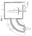
- Fig. 1 is a schematically cross sectional view showing one example of the vacuum arc evaporation apparatus according to the invention.
- the vacuum arc evaporation apparatus has a film forming chamber 1 which is vacuum-evacuatedby a vacuum-evacuating device (not shown).
- a holder 2 is provided for holding a substrate 11 to be film-formed.
- the film forming chamber 1 and a later mentioned plasma duct 5 connected thereto are electrically grounded in this example.
- the holder 2 is supported by a support shaft 3, and rotated in an A direction by a driving part (not shown).
- a gas as an inert gas or a reactive gas is introduced.
- the inert gas is, for example, an argon gas .
- the reacting gas is such a gas reacting with the cathode materials generated from the vacuum arc evaporation source to produce a compound substance, for example, a nitrogen gas.
- the holder 2 and the substrate 11 held thereby are, in this example, impressed with negative bias voltage of, e.g., around -several +V to -1000V from a bias electric source 4.
- negative bias voltage e.g., around -several +V to -1000V from a bias electric source 4.
- positive or negative pulse voltage or high frequency voltage are sometimes impressed.
- the curvedplasma duct 5 is connected such that one-side end of the plasma duct 5 faces to the substrate 11 on the holder 2.
- the interior of this plasma duct 5 is vacuum-evacuated together with the film forming chamber 1.
- the vacuum arc evaporation source 6 has a cathode (target) 7, and partially fuses the cathode 7 to evaporate cathode materials by the vacuum arc discharge between the cathode and the plasma duct 5 serving as an anode in this example.
- the cathode 7 of the vacuum arc evaporation source 6 is composed of a desired material (for example a pure metal, alloy, or carbon) in response to kinds of films to be formed. More specifically, it is composed of pure metals, e.g., Ti, Cr, Mo, Ta, W, Al or Cu, alloys as TiAl, or a graphite (carbon).
- the deflection magnetic filed forming means forms a magnetic field which is curved following the plasma duct 5, and guides the plasma generated in the vacuum arc evaporation source 6 by said magnetic field in the vicinity of the substrate 11 on the holder 2 within the film forming chamber 1.
- the magnetic coil 8 is excited by DC exciting source (not shown) .
- a part of the line of magnetic force 9 generated by exciting the magnetic coil 8 is schematically shown in Fig. 1, following the inside face of the plasma duct 5.
- the magnetic coil 8 used as the magnetic field forming means is solenoid in the present embodiment, and instead of this, a plurality of toridal coils may be disposed on the outer circumference of the plasma duct, otherwise a permanent magnet is sufficient.
- the porous member 10 is disposed on the inside wall of the plasma duct 5. Further, in this embodiment, also on the inside wall of the film forming chamber 1, the porous member 10 is provided.
- Coarse particles of the cathode materials come flying from the cathode 7 into the plasma duct 5 by the vacuum arc discharge, and adhere to and are caught by the porous member 10.
- the porous member 10 is porous, and has a large adhering surface area. Accordingly, the adhering ability is high, and once caught coarse particles do not so much reflect toward the substrate 11.
- plasma having removed coarse particles can be guided in the vicinity of the substrate along the line of magnetic force.
- the porous member 10 is for catching coarse particles, it is desirable that the absorbing surface area is large, and a pore diameter is larger than that of coarse particle, and since it is disposed on the inside wall of the plasma duct, materials of good processability.
- porous bodies of felt-like, mesh-like, non-woven, metal or non metal substances there are enumerated such porous bodies of felt-like, mesh-like, non-woven, metal or non metal substances.
- the felt-like, mesh-like, non-woven porous member have elasticity other than the above mentioned characteristics, and absorb kinetic energy of coarse particles fly-coming, they are effective in decreasing reflecting energy and most preferable.
- the porous member 10 is also sufficient with such materials, after catching the coarse particles fly-coming, having good adaptation between both and good adhesion. Accordingly, the porous member 10 may be composed of a material containing the cathode materials to be evaporated by the vacuum arc discharge or a material containing the cathode materials and covered with a plating or evaporation.
- the porous member 10 may be a carbon containing felt material (carbon felt), a porous carbon material (carbon form) or a carbon mesh material (carbon line materials are stitched together in network).
- carbon felt carbon containing felt material
- carbon form porous carbon material
- carbon mesh material carbon line materials are stitched together in network.
- the porous member 10 is other than carbon, it is useful to previously apply a carbon coating to the porous member 10.
- the porous member may be attached as one body or in division to the inside wall of the plasma duct. Attaching can be easily made by screwing both ends of the porous member, and therefore, maintenance as exchanging is simply performed.
- porous member When the porous member is attached in division to the inside wall of the plasma duct, the plural kinds of porous members may be employed.
- the porous member 10 is also disposed on the inside wall of the film forming chamber 1.
- fine particles adhered to the inside wall neither drop to the substrate 11 nor mix into the film, so that it is possible to form films of good quality having excellent smoothness and adhering property.
- the porous member is arranged almost allover the inside wall of the plasma duct, and of course the porous member may be arranged at one part of the plasma duct such as parts to which coarse particles frequently come flying, or at a plurality of parts.
- the porous member is disposed on the inside wall of the curved plasma duct, and so it is possible to offer the vacuum arc evaporation apparatus at lower production cost and better in the processability as the maintenance than the baffles of the existing plasma duct.
- the porous member also to the inside wall of the film forming chamber, thereby to prevent fine particles adhered to the inside wall of the film forming chamber from dropping, adhering to the substrate and mixing into the film, the film of good quality can be formed.
Landscapes
- Chemical & Material Sciences (AREA)
- Engineering & Computer Science (AREA)
- Physics & Mathematics (AREA)
- Plasma & Fusion (AREA)
- Analytical Chemistry (AREA)
- Epidemiology (AREA)
- Health & Medical Sciences (AREA)
- Public Health (AREA)
- Chemical Kinetics & Catalysis (AREA)
- Materials Engineering (AREA)
- Mechanical Engineering (AREA)
- Metallurgy (AREA)
- Organic Chemistry (AREA)
- Physical Vapour Deposition (AREA)
- Plasma Technology (AREA)
Abstract
Description
- The present invention relates to a film forming apparatus for improving properties such as wear resistance, anti-seizing property, sliding property and others of mechanical parts, automotive parts, tools and the like.
- There is a method for forming a thin film on a surface of a substrate by drawing ions contained in a plasma generated by a vacuum arc evaporation source toward the substrate under negative bias voltage of the like. The vacuum arc evaporation source evaporates a cathode by vacuum arc discharge to thereby generate the plasma containing a cathode material. The method is also called a vacuum arc evaporation method. This method has advantageous features of high film forming rate and high adhesion property.
- The cathode material evaporated from the cathode of the vacuum arc evaporation source contains fine partides preferable for the film-forming, and coarse particles (also called macro-particles or droplets) whose diameter is several µm or larger. These coarse particles come flying and adhere to the substrate, causing problems of decreasing the film-adhesion to the substrate or smoothness of the resultant film surface.
- For conquering this problem, various methods and devices have been proposed. One of them is an apparatus which guides plasma generated by an arc discharge through line of magnetic force to the substrate, and separates and reduces coarse particles concurrently generated. A typical example is described in J. Plasma Phys. 4(1978), 425 to 428 by I.I. Aksenov. This apparatus is composed by communicating a vacuum arc evaporation source, a curved transport duct (plasma duct), and a film forming chamber. The curved transport duct has outside thereof a magnetic field-forming device for guiding the plasma generated in the vacuum arc evaporation source to the substrate having thereby removed coarse particles. The film forming chamber has the substrate accommodated therein.
- There have recently been proposed improved apparatus which guides only ions in plasma generated in the evaporation source by use of the magnetic field to the substrate. As one of examples, explanation will be made to a film forming apparatus described in JP-W-10-505633.
- A film forming apparatus shown in Fig. 2 comprises a
target 33, acontact electrode 35, aplasma duct 39, afirst electromagnet 46, asecond electromagnet 48, and athird electromagnet 50. On thetarget 33, materials evaporated by the arc discharge are generated. Thecontact electrode 35 contacts to thetarget 33 under a condition where negative voltage is impressed to thetarget 33. Theplasma duct 39 is bent almost perpendicularly. Thefirst electromagnet 46 is disposed at an outside of the portion of theplasma duct 39, where thetarget 33 is provided. Thesecond electromagnet 48 is disposed at a bending portion of theplasma duct 39. Thethird electromagnet 50 is disposed at an exit portion of theplasma duct 39 to surround theplasma duct 39. Theplasma duct 39 is provided at the inside wall withbaffles 52 extending toward the inside. - If the
contact electrode 35 contacts thetarget 33 under a condition where negative voltage is impressed to thetarget 33, an arc is generated instantaneously. This arc evaporates the target while staying on the surface of thetarget 33 for a predetermined time to generate the plasma containing a target material. - At this time, when a current is impressed the first, second and
third electromagnets magnetic force 40 is distributed following theplasma duct 39. Accordingly, in plasmas containing the target material generated by thetarget 33, a charged particle (ion) advances following the line of magnetic force (deflection magnetic field) 40, and is sent from an exit of theplasma duct 39 into a film forming chamber (not shown), and evaporated to a substrate (not shown) located in the chamber. Non-ionized neutral particles and coarse particles do not reach the substrate but adhere to theplasma duct 39 and thebaffles 52 disposed on the inside wall of theplasma duct 39. - Therefore, major parts of coarse particles are, as advancing within the
plasma duct 39, removed by adhering to the inside wall of theplasma duct 39 and thebaffles 52. - U.S. Patent No. 5,279,723 and Japanese Patent Unexamined Publication No. Hei. 10-280135 disclose similar devices, each of which is provided, for catching coarse particles, with the baffles, which is composed of a metal ring like member or a vane like member extending toward the inside from the inside wall of the plasma duct, on the inside wall of the bent or curved plasma duct.
- However, problems as mentioned under are involved with the structure of the baffles located on the inside wall of the conventional plasma duct.
- Firstly, as mentioned above, each of the baffles is composed of the metal ring like member or the vane like member extending toward the inside from the inside wall of the plasma duct. Therefore, when coarse particles come flying to parts facing vertically to the plasma duct, they adheres thereto or are reflected in the cathode direction, and when those come flying to a parallel face to the plasma duct, they are reflected with high possibility in the direction of the substrate.
- If many ring or vane like members are provided for repulsing much coarse particles in the target direction, there are inevitably many faces parallel to the plasma duct as mentioned above. Therefore, the number of coarse particle reflected in the direction of the substrate increases, so that the possibility of coarse particles reaching the substrate is high to obstruct the smoothness and adhesion of the film.
- Secondly, for securing many ring or vane like members to the inside wall of the plasma duct, screwing or welding are necessary. Therefore, it takes much processing time and fixture time therefor with high production cost. In case operating for a long time, the baffles should be exchanged for being dirty, and much time is taken for exchanging lots of baffles.
- Thirdly, in the baffle structure as mentioned above, large and small neutral particles adhere to the inside wall of the plasma duct. Therefore, a dirt removing work is demanded when exchanging the baffles, and a maintenance is not easy.
- Other than the problems concerning coarse particles, though being fine particles preferable to the film-forming, some of them do not cover the substrate but adhere to the inside wall of the film forming chamber, and problems occur as under.
- In the above mentioned apparatus, the structure of the inside wall of the film forming chamber accommodating the substrate is not described. Therefore, if the inside wall is the same material as that composing the film forming chamber, fine particles once adhered to the inside wall drop and mix into the film to probably deteriorate a film quality.
- This invention has been established to settle the above described problems. Accordingly, it is an object of the invention to provide a film forming apparatus which forms on a substrate a filmbeing mixed with little coarse or fine particles, and excellent in smoothness, adhesion and quality, and which is good at operating performance such as maintenance of low cost.
- The above mentioned object can be achieved by a film forming apparatus according to the invention, comprising: a vacuum arc evaporation source, a film forming chamber, and a curved plasma duct. The vacuum arc evaporation source generates plasma containing cathode materials by evaporating a cathode through vacuum arc discharge. The film forming chamber accommodates a substrate therein and is vacuum-evacuated. The curved plasma duct has outside thereof a deflection magnetic field forming unit for guiding the plasma generated in the vacuum arc evaporation source in the vicinity of the substrate having removed coarse particles by the curved plasma duct. In the film forming apparatus, the plasma duct has a porous member on the inside wall thereof. Further, the film forming chamber has a porous member on the inside wall thereof.
- According to the film forming apparatus of the invention, the plasma duct has the porous member with a large absorbing surface on the inside wall thereof. Accordingly, coarse particles fly-coming are easily caught because going into pores of the porous member and has a good adhesion with the porous member, thereby preventing the reflection toward the substrate and mixture of coarse particles into the film. If the porous member is also arranged on the inside wall of the film forming chamber, fine particles adhered thereto are not easy to drop, and can be restrained from mixing into the film during film-forming.
- Herein, the porous member for catching coarse particles maybe composed of felt like or mesh like members. The felt-like member is meant by a member made by compressing a line-like member into a cotton-like member, and the mesh-like member is woven into network.
- In particular, if plural sheets of the mesh-like members are laminated, the catching effect of coarse particles is heightened.
- The porous member may be also composed of non-woven, metal or non- metal porous substances. The non-woven fabric is desirably a heat resistant material durable to high temperatures of 200°C or higher if possible. The porous member may be also composed of material including the cathode materials. Because, a material quality containing the cathode materials has a better adaptation to coarse and fine particles and has a stronger adhesion than a material quality not containing the cathode materials, particles catching ability is heightened. Even in the case of not containing the cathode materials, similar effects are available by covering a material in advance containing an element of the cathode materials by an ordinary plating or evaporation.
-
- Fig. 1 is a schematically cross sectional view showing an vacuum arc evaporation apparatus according to the invention; and
- Fig. 2 is a cross sectional view showing one example of a conventional vacuum arc plasma transport apparatus.
-
- Fig. 1 is a schematically cross sectional view showing one example of the vacuum arc evaporation apparatus according to the invention.
- The vacuum arc evaporation apparatus has a film forming chamber 1 which is vacuum-evacuatedby a vacuum-evacuating device (not shown). In the film forming chamber 1, a
holder 2 is provided for holding asubstrate 11 to be film-formed. The film forming chamber 1 and a later mentionedplasma duct 5 connected thereto are electrically grounded in this example. Theholder 2 is supported by asupport shaft 3, and rotated in an A direction by a driving part (not shown). - In the film forming chamber 1, as requested, a gas as an inert gas or a reactive gas is introduced. The inert gas is, for example, an argon gas . The reacting gas is such a gas reacting with the cathode materials generated from the vacuum arc evaporation source to produce a compound substance, for example, a nitrogen gas.
- The
holder 2 and thesubstrate 11 held thereby are, in this example, impressed with negative bias voltage of, e.g., around -several +V to -1000V from a biaselectric source 4. In case a film to be formed or the substrate is electrically insulating substances, positive or negative pulse voltage or high frequency voltage are sometimes impressed. - At an opening part in the wall face of the film forming chamber 1, the
curvedplasma duct 5 is connected such that one-side end of theplasma duct 5 faces to thesubstrate 11 on theholder 2. The interior of thisplasma duct 5 is vacuum-evacuated together with the film forming chamber 1. - To another end of the
plasma duct 5, a vacuum arc evaporation source 6 is connected. The vacuum arc evaporation source 6 has a cathode (target) 7, and partially fuses the cathode 7 to evaporate cathode materials by the vacuum arc discharge between the cathode and theplasma duct 5 serving as an anode in this example. - The cathode 7 of the vacuum arc evaporation source 6 is composed of a desired material (for example a pure metal, alloy, or carbon) in response to kinds of films to be formed. More specifically, it is composed of pure metals, e.g., Ti, Cr, Mo, Ta, W, Al or Cu, alloys as TiAl, or a graphite (carbon).
- Around the outer circumference of the
plasma duct 5, there is provided means for forming deflection magnetic filed. The deflection magnetic filed forming means forms a magnetic field which is curved following theplasma duct 5, and guides the plasma generated in the vacuum arc evaporation source 6 by said magnetic field in the vicinity of thesubstrate 11 on theholder 2 within the film forming chamber 1. Themagnetic coil 8 is excited by DC exciting source (not shown) . A part of the line ofmagnetic force 9 generated by exciting themagnetic coil 8 is schematically shown in Fig. 1, following the inside face of theplasma duct 5. - The
magnetic coil 8 used as the magnetic field forming means is solenoid in the present embodiment, and instead of this, a plurality of toridal coils may be disposed on the outer circumference of the plasma duct, otherwise a permanent magnet is sufficient. - The
porous member 10 is disposed on the inside wall of theplasma duct 5. Further, in this embodiment, also on the inside wall of the film forming chamber 1, theporous member 10 is provided. - Coarse particles of the cathode materials come flying from the cathode 7 into the
plasma duct 5 by the vacuum arc discharge, and adhere to and are caught by theporous member 10. Theporous member 10 is porous, and has a large adhering surface area. Accordingly, the adhering ability is high, and once caught coarse particles do not so much reflect toward thesubstrate 11. - Thus, according to the inventive apparatus, plasma having removed coarse particles can be guided in the vicinity of the substrate along the line of magnetic force.
- As the
porous member 10 is for catching coarse particles, it is desirable that the absorbing surface area is large, and a pore diameter is larger than that of coarse particle, and since it is disposed on the inside wall of the plasma duct, materials of good processability. Actually, there are enumerated such porous bodies of felt-like, mesh-like, non-woven, metal or non metal substances. In particular, since the felt-like, mesh-like, non-woven porous member have elasticity other than the above mentioned characteristics, and absorb kinetic energy of coarse particles fly-coming, they are effective in decreasing reflecting energy and most preferable. - The
porous member 10 is also sufficient with such materials, after catching the coarse particles fly-coming, having good adaptation between both and good adhesion. Accordingly, theporous member 10 may be composed of a material containing the cathode materials to be evaporated by the vacuum arc discharge or a material containing the cathode materials and covered with a plating or evaporation. - For example, when the vacuum arc evaporation source 6 is attached with the cathode 7 of graphite and the
substrate 11 is formed with a carbon film by evaporating the cathode, theporous member 10 may be a carbon containing felt material (carbon felt), a porous carbon material (carbon form) or a carbon mesh material (carbon line materials are stitched together in network). In case theporous member 10 is other than carbon, it is useful to previously apply a carbon coating to theporous member 10. - The porous member may be attached as one body or in division to the inside wall of the plasma duct. Attaching can be easily made by screwing both ends of the porous member, and therefore, maintenance as exchanging is simply performed.
- When the porous member is attached in division to the inside wall of the plasma duct, the plural kinds of porous members may be employed.
- In the example of Fig. 1, the
porous member 10 is also disposed on the inside wall of the film forming chamber 1. In this case, fine particles adhered to the inside wall neither drop to thesubstrate 11 nor mix into the film, so that it is possible to form films of good quality having excellent smoothness and adhering property. - Further, in the example of Fig. 1, the porous member is arranged almost allover the inside wall of the plasma duct, and of course the porous member may be arranged at one part of the plasma duct such as parts to which coarse particles frequently come flying, or at a plurality of parts.
- As mentioned above, according to the invention, the porous member is disposed on the inside wall of the curved plasma duct, and so it is possible to offer the vacuum arc evaporation apparatus at lower production cost and better in the processability as the maintenance than the baffles of the existing plasma duct.
- As coarse particles generated by the vacuum arc discharge can be securely caught, and plasma having removed coarse particles can be guided nearly the substrate, it is possible to form films of good quality having the surface smoothness and the good adhesion with the substrate.
- Besides, disposing the porous member also to the inside wall of the film forming chamber, thereby to prevent fine particles adhered to the inside wall of the film forming chamber from dropping, adhering to the substrate and mixing into the film, the film of good quality can be formed.
Claims (18)
- A film forming apparatus comprising:a vacuum arc evaporation source for generating plasma containing cathode materials by evaporating a cathode through vacuum arc discharge;a film forming chamber for accommodating a substrate therein and being vacuum-evacuated; anda curved plasma duct having outside thereof a deflection magnetic field forming unit for guiding said plasma generated in the vacuum arc evaporation source in the vicinity of the substrate having removed coarse particles by the curved plasma duct,wherein the plasma duct has a porous member on an inside wall thereof.
- The film forming apparatus according to claim 1, wherein the film forming chamber has a porous member on an inside walls thereof.
- The film forming apparatus according to claim 1, wherein the porous member is a felt-like member.
- The film forming apparatus according to claim 2, wherein the porous member is a felt-like member.
- The film forming apparatus according to claim 1, wherein the porous member is at least one mesh-like member.
- The film forming apparatus according to claim 2, wherein the porous member is at least one mesh-like member.
- The film forming apparatus according to claim 1, wherein the porous member is a non-woven fabric.
- The film forming apparatus according to claim 2, wherein the porous member is a non-woven fabric.
- The film forming apparatus according to claim 1, wherein the porous member is a metal or a non metal porous member.
- The film forming apparatus according to claim 2, wherein the porous member is a metal or a nonmetal porous member .
- The film forming apparatus according to claim 1, wherein the porous member is composed of a material containing the cathode materials.
- The film forming apparatus according to claim 2, wherein the porous member is composed of a material containing the cathode materials.
- The film forming apparatus according to claim 1, wherein the porous member is composed of a member which is covered with the material containing the cathode materials.
- The film forming apparatus according to claim 2, wherein the porous member is composed of a member which is covered with the material containing the cathode materials.
- The film forming apparatus according to claim 5, wherein the mesh-like members are laminated.
- The film forming apparatus according to claim 6, wherein the mesh-like members are laminated.
- The film forming apparatus according to claim 1, wherein the porous member is arranged almost allover the inside wall of the plasma duct.
- The film forming apparatus according to claim 1, wherein the porous member is arranged at one part of the plasma duct such as parts to which coarse particles frequently come flying, or at a plurality of parts.
Applications Claiming Priority (2)
| Application Number | Priority Date | Filing Date | Title |
|---|---|---|---|
| JP2000303266A JP2002105628A (en) | 2000-10-03 | 2000-10-03 | Vacuum arc deposition equipment |
| JP2000303266 | 2000-10-03 |
Publications (2)
| Publication Number | Publication Date |
|---|---|
| EP1195792A2 true EP1195792A2 (en) | 2002-04-10 |
| EP1195792A3 EP1195792A3 (en) | 2004-10-06 |
Family
ID=18784486
Family Applications (1)
| Application Number | Title | Priority Date | Filing Date |
|---|---|---|---|
| EP01123260A Withdrawn EP1195792A3 (en) | 2000-10-03 | 2001-10-02 | Film forming apparatus |
Country Status (4)
| Country | Link |
|---|---|
| US (1) | US6506292B2 (en) |
| EP (1) | EP1195792A3 (en) |
| JP (1) | JP2002105628A (en) |
| KR (1) | KR100610412B1 (en) |
Cited By (2)
| Publication number | Priority date | Publication date | Assignee | Title |
|---|---|---|---|---|
| EP2068602A4 (en) * | 2006-09-30 | 2009-11-25 | Ferrotec Corp | PLASMA GENERATOR APPARATUS OF EXTENDED RANGE |
| WO2011069908A1 (en) * | 2009-12-09 | 2011-06-16 | Roth & Rau Ag | Ecr plasma source with coating protection and use of the coating protection |
Families Citing this family (23)
| Publication number | Priority date | Publication date | Assignee | Title |
|---|---|---|---|---|
| JP3826108B2 (en) * | 2002-04-24 | 2006-09-27 | キヤノン株式会社 | Film forming apparatus and film forming method |
| JP2005029855A (en) * | 2003-07-08 | 2005-02-03 | Fuji Electric Device Technology Co Ltd | Vacuum arc deposition apparatus, vacuum arc deposition method, and magnetic recording medium |
| US20050249983A1 (en) * | 2004-05-06 | 2005-11-10 | Seagate Technology Llc | Thickness gradient protective overcoat layers by filtered cathodic arc deposition |
| JP2008291326A (en) * | 2007-05-25 | 2008-12-04 | Fujitsu Ltd | Film forming apparatus and film forming method |
| US7872244B2 (en) * | 2007-08-08 | 2011-01-18 | Asml Netherlands B.V. | Lithographic apparatus and device manufacturing method |
| JP4568768B2 (en) | 2008-03-27 | 2010-10-27 | 株式会社フェローテック | Plasma generating apparatus and plasma processing apparatus |
| TWI379916B (en) * | 2009-02-24 | 2012-12-21 | Ind Tech Res Inst | Vacuum coating device and coating method |
| JP4576467B2 (en) | 2009-03-31 | 2010-11-10 | 株式会社フェローテック | Insulator-interposed plasma processing equipment |
| JP2010287268A (en) * | 2009-06-10 | 2010-12-24 | Fuji Electric Device Technology Co Ltd | Filtered cathodic arc apparatus and carbon protective film formed using the same |
| JP5429802B2 (en) * | 2009-12-26 | 2014-02-26 | キヤノンアネルバ株式会社 | Vacuum arc evaporation system |
| US9024273B2 (en) * | 2010-04-20 | 2015-05-05 | Varian Semiconductor Equipment Associates, Inc. | Method to generate molecular ions from ions with a smaller atomic mass |
| JP5606777B2 (en) * | 2010-04-22 | 2014-10-15 | 株式会社フェローテック | Plasma flow generation method, plasma processing method, plasma generator, and plasma processing apparatus |
| EP2949779A4 (en) | 2013-01-22 | 2016-10-05 | Nissin Electric Co Ltd | Plasma device, carbon thin film manufacturing method and coating method using plasma device |
| JPWO2014171208A1 (en) * | 2013-04-18 | 2017-02-16 | 株式会社日立製作所 | Gas circuit breaker |
| US9840765B2 (en) * | 2013-10-16 | 2017-12-12 | General Electric Company | Systems and method of coating an interior surface of an object |
| JP2016027604A (en) * | 2014-06-24 | 2016-02-18 | 株式会社荏原製作所 | Surface treatment equipment |
| JP6347414B2 (en) * | 2014-11-04 | 2018-06-27 | 日新イオン機器株式会社 | Mass spectrometry electromagnet |
| JP6059195B2 (en) | 2014-11-06 | 2017-01-11 | キヤノンアネルバ株式会社 | Deposition equipment |
| KR101616855B1 (en) * | 2014-11-11 | 2016-04-29 | 한국기계연구원 | A vacuum arc deposition device comprising plasma duct |
| KR101639630B1 (en) * | 2014-12-11 | 2016-07-15 | 한국기계연구원 | A vacuum arc deposition device comprising plasma duct |
| EP3263737B1 (en) * | 2016-06-29 | 2019-06-12 | Oerlikon Surface Solutions AG, Pfäffikon | Vacuum coating chamber and method for filtering macroparticles during cathodic arc evaporation |
| CN108085640B (en) * | 2017-10-31 | 2023-05-12 | 东莞市汇成真空科技有限公司 | Vacuum cathode arc coating machine for coating inner wall of large tank body |
| CN111741582A (en) * | 2020-07-02 | 2020-10-02 | 安徽纯源镀膜科技有限公司 | Transmission channel device for plasma transmission and coating equipment |
Family Cites Families (8)
| Publication number | Priority date | Publication date | Assignee | Title |
|---|---|---|---|---|
| DE3634710A1 (en) * | 1986-10-11 | 1988-04-21 | Ver Glaswerke Gmbh | DEVICE FOR VACUUM COATING A GLASS DISC BY REACTIVE CATHODAL SPRAYING |
| US5637199A (en) * | 1992-06-26 | 1997-06-10 | Minnesota Mining And Manufacturing Company | Sputtering shields and method of manufacture |
| US5279723A (en) | 1992-07-30 | 1994-01-18 | As Represented By The United States Department Of Energy | Filtered cathodic arc source |
| US5480527A (en) | 1994-04-25 | 1996-01-02 | Vapor Technologies, Inc. | Rectangular vacuum-arc plasma source |
| US5455426A (en) * | 1994-06-15 | 1995-10-03 | Texas Instruments Incorporated | Target chamber shielding |
| GB9503305D0 (en) * | 1995-02-20 | 1995-04-12 | Univ Nanyang | Filtered cathodic arc source |
| US5656092A (en) * | 1995-12-18 | 1997-08-12 | Eaton Corporation | Apparatus for capturing and removing contaminant particles from an interior region of an ion implanter |
| KR100230279B1 (en) * | 1997-03-31 | 1999-11-15 | 윤종용 | Coating apparatus by using cathodic arc discharge |
-
2000
- 2000-10-03 JP JP2000303266A patent/JP2002105628A/en active Pending
-
2001
- 2001-09-28 KR KR1020010060317A patent/KR100610412B1/en not_active Expired - Fee Related
- 2001-10-02 EP EP01123260A patent/EP1195792A3/en not_active Withdrawn
- 2001-10-02 US US09/968,016 patent/US6506292B2/en not_active Expired - Fee Related
Non-Patent Citations (1)
| Title |
|---|
| None * |
Cited By (2)
| Publication number | Priority date | Publication date | Assignee | Title |
|---|---|---|---|---|
| EP2068602A4 (en) * | 2006-09-30 | 2009-11-25 | Ferrotec Corp | PLASMA GENERATOR APPARATUS OF EXTENDED RANGE |
| WO2011069908A1 (en) * | 2009-12-09 | 2011-06-16 | Roth & Rau Ag | Ecr plasma source with coating protection and use of the coating protection |
Also Published As
| Publication number | Publication date |
|---|---|
| KR100610412B1 (en) | 2006-08-09 |
| JP2002105628A (en) | 2002-04-10 |
| US20020074226A1 (en) | 2002-06-20 |
| US6506292B2 (en) | 2003-01-14 |
| EP1195792A3 (en) | 2004-10-06 |
| KR20020026833A (en) | 2002-04-12 |
Similar Documents
| Publication | Publication Date | Title |
|---|---|---|
| US6506292B2 (en) | Film forming apparatus | |
| US5126030A (en) | Apparatus and method of cathodic arc deposition | |
| US9127354B2 (en) | Filtered cathodic arc deposition apparatus and method | |
| US5580429A (en) | Method for the deposition and modification of thin films using a combination of vacuum arcs and plasma immersion ion implantation | |
| US20100129615A1 (en) | Process and apparatus for the modification of surfaces | |
| CZ293994B6 (en) | Razor blade, process for its manufacture and shaving unit | |
| EP2426231A1 (en) | Arc evaporation source and method for manufacturing film using same | |
| US9005780B2 (en) | Rare earth magnet, method for producing same and method for producing multilayer body | |
| WO2005089031A1 (en) | Plasma generator | |
| JP2002008893A (en) | Plasma processing method | |
| WO2010113544A1 (en) | Insulator-interposed plasma processing device | |
| EP4506484A1 (en) | Film-forming device | |
| CN103732785B (en) | Cathodic arc deposition | |
| EP1170776A2 (en) | Vacuum arc evaporation source and film formation apparatus using the same | |
| WO2003087425A1 (en) | Filtered ion source | |
| JP2007009303A (en) | Plasma surface treatment method, plasma treatment apparatus, and workpiece | |
| US20140034484A1 (en) | Device for the elimination of liquid droplets from a cathodic arc plasma source | |
| EP3382737A1 (en) | Plasma process and reactor for the thermochemical treatment of the surface of metallic pieces | |
| EP1081247A2 (en) | Arc type ion plating apparatus | |
| EP2539480A1 (en) | Plasma sputtering process for producing particles | |
| US6287463B1 (en) | Collector cup | |
| JP4019457B2 (en) | Arc type evaporation source | |
| JP5454386B2 (en) | Vacuum arc evaporation system | |
| JP4019464B2 (en) | Arc type evaporation source | |
| JP2011157572A (en) | Method for enhancing denseness of metal film to be vapor-deposited |
Legal Events
| Date | Code | Title | Description |
|---|---|---|---|
| PUAI | Public reference made under article 153(3) epc to a published international application that has entered the european phase |
Free format text: ORIGINAL CODE: 0009012 |
|
| AK | Designated contracting states |
Kind code of ref document: A2 Designated state(s): AT BE CH CY DE DK ES FI FR GB GR IE IT LI LU MC NL PT SE TR |
|
| AX | Request for extension of the european patent |
Free format text: AL;LT;LV;MK;RO;SI |
|
| PUAL | Search report despatched |
Free format text: ORIGINAL CODE: 0009013 |
|
| AK | Designated contracting states |
Kind code of ref document: A3 Designated state(s): AT BE CH CY DE DK ES FI FR GB GR IE IT LI LU MC NL PT SE TR |
|
| AX | Request for extension of the european patent |
Extension state: AL LT LV MK RO SI |
|
| 17P | Request for examination filed |
Effective date: 20050207 |
|
| AKX | Designation fees paid |
Designated state(s): DE FR GB |
|
| 17Q | First examination report despatched |
Effective date: 20060214 |
|
| STAA | Information on the status of an ep patent application or granted ep patent |
Free format text: STATUS: THE APPLICATION IS DEEMED TO BE WITHDRAWN |
|
| 18D | Application deemed to be withdrawn |
Effective date: 20110503 |