EP1195542A1 - Hydro mechanical transmission - Google Patents
Hydro mechanical transmission Download PDFInfo
- Publication number
- EP1195542A1 EP1195542A1 EP01121882A EP01121882A EP1195542A1 EP 1195542 A1 EP1195542 A1 EP 1195542A1 EP 01121882 A EP01121882 A EP 01121882A EP 01121882 A EP01121882 A EP 01121882A EP 1195542 A1 EP1195542 A1 EP 1195542A1
- Authority
- EP
- European Patent Office
- Prior art keywords
- speed
- output shaft
- unit output
- hydrostatic unit
- transmission
- Prior art date
- Legal status (The legal status is an assumption and is not a legal conclusion. Google has not performed a legal analysis and makes no representation as to the accuracy of the status listed.)
- Granted
Links
- ZZUFCTLCJUWOSV-UHFFFAOYSA-N furosemide Chemical compound C1=C(Cl)C(S(=O)(=O)N)=CC(C(O)=O)=C1NCC1=CC=CO1 ZZUFCTLCJUWOSV-UHFFFAOYSA-N 0.000 title claims description 4
- 230000009347 mechanical transmission Effects 0.000 title 1
- 230000002706 hydrostatic effect Effects 0.000 claims abstract description 51
- 230000005540 biological transmission Effects 0.000 claims abstract description 49
- 238000005259 measurement Methods 0.000 claims description 7
- 238000000034 method Methods 0.000 claims description 4
- 238000012935 Averaging Methods 0.000 claims 2
- 125000001145 hydrido group Chemical group *[H] 0.000 abstract description 33
- 230000003247 decreasing effect Effects 0.000 abstract 1
- 230000005355 Hall effect Effects 0.000 description 4
- 238000011161 development Methods 0.000 description 2
- 230000018109 developmental process Effects 0.000 description 2
- 230000007704 transition Effects 0.000 description 2
- 230000001419 dependent effect Effects 0.000 description 1
Images
Classifications
-
- F—MECHANICAL ENGINEERING; LIGHTING; HEATING; WEAPONS; BLASTING
- F16—ENGINEERING ELEMENTS AND UNITS; GENERAL MEASURES FOR PRODUCING AND MAINTAINING EFFECTIVE FUNCTIONING OF MACHINES OR INSTALLATIONS; THERMAL INSULATION IN GENERAL
- F16H—GEARING
- F16H59/00—Control inputs to control units of change-speed- or reversing-gearings for conveying rotary motion
- F16H59/36—Inputs being a function of speed
- F16H59/38—Inputs being a function of speed of gearing elements
-
- F—MECHANICAL ENGINEERING; LIGHTING; HEATING; WEAPONS; BLASTING
- F16—ENGINEERING ELEMENTS AND UNITS; GENERAL MEASURES FOR PRODUCING AND MAINTAINING EFFECTIVE FUNCTIONING OF MACHINES OR INSTALLATIONS; THERMAL INSULATION IN GENERAL
- F16H—GEARING
- F16H47/00—Combinations of mechanical gearing with fluid clutches or fluid gearing
- F16H47/02—Combinations of mechanical gearing with fluid clutches or fluid gearing the fluid gearing being of the volumetric type
- F16H47/04—Combinations of mechanical gearing with fluid clutches or fluid gearing the fluid gearing being of the volumetric type the mechanical gearing being of the type with members having orbital motion
-
- F—MECHANICAL ENGINEERING; LIGHTING; HEATING; WEAPONS; BLASTING
- F16—ENGINEERING ELEMENTS AND UNITS; GENERAL MEASURES FOR PRODUCING AND MAINTAINING EFFECTIVE FUNCTIONING OF MACHINES OR INSTALLATIONS; THERMAL INSULATION IN GENERAL
- F16H—GEARING
- F16H59/00—Control inputs to control units of change-speed- or reversing-gearings for conveying rotary motion
- F16H59/36—Inputs being a function of speed
- F16H59/46—Inputs being a function of speed dependent on a comparison between speeds
-
- F—MECHANICAL ENGINEERING; LIGHTING; HEATING; WEAPONS; BLASTING
- F16—ENGINEERING ELEMENTS AND UNITS; GENERAL MEASURES FOR PRODUCING AND MAINTAINING EFFECTIVE FUNCTIONING OF MACHINES OR INSTALLATIONS; THERMAL INSULATION IN GENERAL
- F16H—GEARING
- F16H37/00—Combinations of mechanical gearings, not provided for in groups F16H1/00 - F16H35/00
- F16H37/02—Combinations of mechanical gearings, not provided for in groups F16H1/00 - F16H35/00 comprising essentially only toothed or friction gearings
- F16H37/06—Combinations of mechanical gearings, not provided for in groups F16H1/00 - F16H35/00 comprising essentially only toothed or friction gearings with a plurality of driving or driven shafts; with arrangements for dividing torque between two or more intermediate shafts
- F16H37/08—Combinations of mechanical gearings, not provided for in groups F16H1/00 - F16H35/00 comprising essentially only toothed or friction gearings with a plurality of driving or driven shafts; with arrangements for dividing torque between two or more intermediate shafts with differential gearing
- F16H37/0833—Combinations of mechanical gearings, not provided for in groups F16H1/00 - F16H35/00 comprising essentially only toothed or friction gearings with a plurality of driving or driven shafts; with arrangements for dividing torque between two or more intermediate shafts with differential gearing with arrangements for dividing torque between two or more intermediate shafts, i.e. with two or more internal power paths
- F16H37/084—Combinations of mechanical gearings, not provided for in groups F16H1/00 - F16H35/00 comprising essentially only toothed or friction gearings with a plurality of driving or driven shafts; with arrangements for dividing torque between two or more intermediate shafts with differential gearing with arrangements for dividing torque between two or more intermediate shafts, i.e. with two or more internal power paths at least one power path being a continuously variable transmission, i.e. CVT
- F16H2037/088—Power-split transmissions with summing differentials, with the input of the CVT connected or connectable to the input shaft
-
- F—MECHANICAL ENGINEERING; LIGHTING; HEATING; WEAPONS; BLASTING
- F16—ENGINEERING ELEMENTS AND UNITS; GENERAL MEASURES FOR PRODUCING AND MAINTAINING EFFECTIVE FUNCTIONING OF MACHINES OR INSTALLATIONS; THERMAL INSULATION IN GENERAL
- F16H—GEARING
- F16H59/00—Control inputs to control units of change-speed- or reversing-gearings for conveying rotary motion
- F16H59/36—Inputs being a function of speed
- F16H59/38—Inputs being a function of speed of gearing elements
- F16H59/40—Output shaft speed
-
- F—MECHANICAL ENGINEERING; LIGHTING; HEATING; WEAPONS; BLASTING
- F16—ENGINEERING ELEMENTS AND UNITS; GENERAL MEASURES FOR PRODUCING AND MAINTAINING EFFECTIVE FUNCTIONING OF MACHINES OR INSTALLATIONS; THERMAL INSULATION IN GENERAL
- F16H—GEARING
- F16H59/00—Control inputs to control units of change-speed- or reversing-gearings for conveying rotary motion
- F16H59/36—Inputs being a function of speed
- F16H59/38—Inputs being a function of speed of gearing elements
- F16H59/42—Input shaft speed
Definitions
- the present invention relates to a hydro-mechanical transmission having a hydrostatic unit and in particular to a method and means for determining the actual output speed of the hydrostatic unit.
- the controller of a hydro-mechanical transmission commands a given output speed for the hydrostatic unit based on a variety of input factors. For proper control it is necessary to have a feedback to the controller of the actual output speed of the hydrostatic unit.
- This has been provided in the past by the use of a directional Hall effect sensor and a magnetic ring carried on the hydro unit output shaft or on a gear driven by the hydro unit output shaft.
- One drawback of this approach is that the directional Hall effect sensors and the magnetic ring are relatively expensive.
- Another drawback is that when the hydrostatic unit is at near zero stroke, the hydro unit output speed is low and the frequency of the speed pulses is also low. Therefore the update rate for measuring the hydro unit output speed is slow.
- the transmission uses two, non-directional, relatively inexpensive variable reluctance speed sensors on different gears in the transmission to accurately determine the speed and direction of the hydrostatic unit output.
- One sensor is on the hydro unit output of the hydrostatic unit and measures the hydro unit output speed directly.
- the other sensor is on the transmission planetary carrier and measures the hydro unit output speed indirectly.
- the hydro unit output speed must be calculated based on the current engine speed and the known transmission gear ratios.
- the hydrostatic unit is stopped or turning at a slow speed
- the carrier is turning at a relatively fast speed.
- the hydrostatic unit output shaft is turning at a relatively fast speed.
- the sensor that is measuring the faster actual speed is the sensor that is used to determine the hydro unit output speed.
- variable reluctance sensors are inexpensive and can measure existing gears in the transmission without the need for a pressed-on magnetic ring. Furthermore, having two sensors to measure the hydrostatic unit speed allows for error checking and onboard diagnostics by the controller.
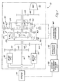
- the hydro-mechanical transmission of the present invention is shown in Fig. 1 and designated generally at 10.
- the transmission 10 is adapted to be driven by an engine 12 having an output shaft 14.
- the transmission further includes a hydrostatic unit including a variable speed pump 16 and a motor 18 driven by the pump 16.
- the engine output shaft 14 drives the hydrostatic pump 16 through gears N2 and N1.
- the transmission includes a planetary system 20 having first and second planetary gear sets 24 and 26.
- the planetary gear sets 24, 26 have a common planetary carrier 28 that carries the integral planet gears P1 and P2 of the two planetary gear sets respectively.
- a single ring gear R2 is provided that meshes with the planet gears P2.
- the engine output shaft 14 also drives the sun gear S1 of the first planetary gear set 24.
- the second planetary gear set 26 has a sun gear S2.
- the transmission includes two clutches, a low range clutch CL and a high range clutch CH.
- the clutch CL is engagable to couple the carrier 28 to the differential drive shaft 42 through the gears N5 and N6.
- the clutch CH is engagable to couple the sun gear S2 to the differential drive shaft 42 through the gears N5 and N6.
- the transmission also includes a reversing planetary gear set 30 having a ring gear R3, planet gears P3 and a sun gear S3. When the brake BR is engaged to stop the rotation of the ring gear R3 and the two clutches are disengaged, sun gear S3 will rotate in the opposite direction, thereby changing the direction of rotation of the drive shaft 42.
- the transmission includes an electronic controller 44 that communicates with the hydraulic controls 46 to operate the transmission 10.
- the hydraulic controls are used to control the output of the hydrostatic variable unit 16 as well as to engage and disengage the clutches CL, CH and the brake BR in the transmission.
- the controller 44 also communicates with the engine electronic control unit 48 to coordinate the control of the engine 12 and the transmission 10.
- the transmission controller 44 receives, among other things, an input from the engine electronic control unit 48 regarding the speed of the engine which is the speed of the sun gear S1.
- the electronic controller 44 commands a speed for the hydro unit output shaft 50 that drives the gear N4.
- a closed loop speed control system in which the actual speed of the hydro unit output shaft 50 is provided to the controller 44.
- a first variable reluctance speed sensor 58 measures the speed of the ring gear R2 which is driven by the hydro unit output through the gears N3 and N4.
- the speed of R2 is directly proportional to the hydro unit output speed.
- the sensor 58 can be located to measure the speed of the gear N4 on the hydro unit output shaft. The sensor 58 provides a direct measure of the hydro unit output speed.
- a second variable reluctance speed sensor 60 measures the speed of the planetary carrier 28. This is an indirect measure of the hydro unit output speed as the electronic controller 44 must calculate the hydro unit output speed from the carrier speed and the speed of sun gear S1.
- P1, S1, etc. represent the number of teeth on the respective gears.
- the resulting value will be either positive or negative, thus indicating the direction of rotation of the hydro unit output.
- This equation can be used at all times to determine the direction of the hydro output even when the hydro unit output speed is determined by the sensor 58 on the ring gear R2.
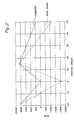
- the speed of the carrier 28 and the speed of the ring gear R2 are shown in relation to the vehicle ground speed. As can be seen, neither the carrier speed nor the ring gear speed are at zero or close to zero at the same ground speed. One of the two is always turning at a speed fast enough to give the needed measurement frequency for the hydro unit output. Whichever sensor of the two sensors 58, 60 is measuring the fastest actual speed is the sensor used to determine the measured hydro unit output speed. When the two speeds actually measured by the sensors are close to the same, e.g. within 10 percent of one another, the hydro unit output speeds as determined by both of the two sensors are averaged together. The averaged value is used by the controller as the hydro unit output speed.
- the frequency of the speed measurement is always greater than 250Hz even when the hydrostatic unit is stopped or near stopped.
- the carrier 28 for the indirect measure of the hydro unit output speed.
- other components of the transmission driven by the planetary gear set 24 can be used in this measurement.
- the speeds of sun gears S2 or S3 could be measured and the hydro unit output speed calculated therefrom.
- clutch slippage may be a complicating factor. This is why the carrier speed is preferred, since clutch slippage is not a factor in calculating the hydro unit output speed.
Landscapes
- Engineering & Computer Science (AREA)
- General Engineering & Computer Science (AREA)
- Mechanical Engineering (AREA)
- Control Of Transmission Device (AREA)
- Structure Of Transmissions (AREA)
- Medicines Containing Plant Substances (AREA)
Abstract
Description
- The present invention relates to a hydro-mechanical transmission having a hydrostatic unit and in particular to a method and means for determining the actual output speed of the hydrostatic unit.
- The controller of a hydro-mechanical transmission commands a given output speed for the hydrostatic unit based on a variety of input factors. For proper control it is necessary to have a feedback to the controller of the actual output speed of the hydrostatic unit. This has been provided in the past by the use of a directional Hall effect sensor and a magnetic ring carried on the hydro unit output shaft or on a gear driven by the hydro unit output shaft. One drawback of this approach is that the directional Hall effect sensors and the magnetic ring are relatively expensive. Another drawback is that when the hydrostatic unit is at near zero stroke, the hydro unit output speed is low and the frequency of the speed pulses is also low. Therefore the update rate for measuring the hydro unit output speed is slow.
- It is therefore an object of the present invention to overcome the above drawbacks associated with the use of a directional Hall effect speed sensor.
- This and other objects are achieved by the present invention according to one of the
claims 1 or 16. Further advantageous arrangements and developments of the invention appear from the dependent claims. - In an advantageous embodiment of the present invention the transmission uses two, non-directional, relatively inexpensive variable reluctance speed sensors on different gears in the transmission to accurately determine the speed and direction of the hydrostatic unit output. One sensor is on the hydro unit output of the hydrostatic unit and measures the hydro unit output speed directly. The other sensor is on the transmission planetary carrier and measures the hydro unit output speed indirectly. The hydro unit output speed must be calculated based on the current engine speed and the known transmission gear ratios. When the hydrostatic unit is stopped or turning at a slow speed, the carrier is turning at a relatively fast speed. Furthermore, when the carrier is stopped or turning at a slow speed, the hydrostatic unit output shaft is turning at a relatively fast speed. The sensor that is measuring the faster actual speed is the sensor that is used to determine the hydro unit output speed. There is a transition period during which the two measured speeds are relatively close to one another. In the transition period, the hydro unit output speeds determined by the two sensors are averaged and the average value used by the controller as the hydro unit output speed.
- By using the sensor with the highest actual speed measurement, the frequency of the speed measurement is always greater than or equal to 250 Hz. As a result, a new and accurate speed can be measured every 4 ms for closed loop speed control. The variable reluctance sensors are inexpensive and can measure existing gears in the transmission without the need for a pressed-on magnetic ring. Furthermore, having two sensors to measure the hydrostatic unit speed allows for error checking and onboard diagnostics by the controller.
- The invention and further advantageous developments and arrangements of the invention will now be described and explained in more detail by way of example and with reference to the accompanying drawings in which:
- Fig. 1
- is a schematic of the hydro-mechanical transmission of the present invention and
- Fig. 2
- is a graph showing the ring gear speed and the planet carrier speed versus vehicle ground speed.
- The hydro-mechanical transmission of the present invention is shown in Fig. 1 and designated generally at 10. The
transmission 10 is adapted to be driven by anengine 12 having anoutput shaft 14. The transmission further includes a hydrostatic unit including avariable speed pump 16 and amotor 18 driven by thepump 16. Theengine output shaft 14 drives thehydrostatic pump 16 through gears N2 and N1. - The transmission includes a
planetary system 20 having first and second planetary gear sets 24 and 26. The planetary gear sets 24, 26 have a commonplanetary carrier 28 that carries the integral planet gears P1 and P2 of the two planetary gear sets respectively. A single ring gear R2 is provided that meshes with the planet gears P2. Theengine output shaft 14 also drives the sun gear S1 of the first planetary gear set 24. The second planetary gear set 26 has a sun gear S2. - The transmission includes two clutches, a low range clutch CL and a high range clutch CH. The clutch CL is engagable to couple the
carrier 28 to thedifferential drive shaft 42 through the gears N5 and N6. The clutch CH is engagable to couple the sun gear S2 to thedifferential drive shaft 42 through the gears N5 and N6. The transmission also includes a reversing planetary gear set 30 having a ring gear R3, planet gears P3 and a sun gear S3. When the brake BR is engaged to stop the rotation of the ring gear R3 and the two clutches are disengaged, sun gear S3 will rotate in the opposite direction, thereby changing the direction of rotation of thedrive shaft 42. - The transmission includes an
electronic controller 44 that communicates with thehydraulic controls 46 to operate thetransmission 10. The hydraulic controls are used to control the output of the hydrostaticvariable unit 16 as well as to engage and disengage the clutches CL, CH and the brake BR in the transmission. Thecontroller 44 also communicates with the engineelectronic control unit 48 to coordinate the control of theengine 12 and thetransmission 10. Thetransmission controller 44 receives, among other things, an input from the engineelectronic control unit 48 regarding the speed of the engine which is the speed of the sun gear S1. - The
electronic controller 44 commands a speed for the hydrounit output shaft 50 that drives the gear N4. In order to control the transmission, it is necessary to have a closed loop speed control system in which the actual speed of the hydrounit output shaft 50 is provided to thecontroller 44. - A first variable
reluctance speed sensor 58 measures the speed of the ring gear R2 which is driven by the hydro unit output through the gears N3 and N4. The speed of R2 is directly proportional to the hydro unit output speed. Alternatively, thesensor 58 can be located to measure the speed of the gear N4 on the hydro unit output shaft. Thesensor 58 provides a direct measure of the hydro unit output speed. - A second variable
reluctance speed sensor 60 measures the speed of theplanetary carrier 28. This is an indirect measure of the hydro unit output speed as theelectronic controller 44 must calculate the hydro unit output speed from the carrier speed and the speed of sun gear S1. The hydro unit output speed is calculated by the following equation:sensor 58 on the ring gear R2. - With reference to Fig. 2, the speed of the
carrier 28 and the speed of the ring gear R2 are shown in relation to the vehicle ground speed. As can be seen, neither the carrier speed nor the ring gear speed are at zero or close to zero at the same ground speed. One of the two is always turning at a speed fast enough to give the needed measurement frequency for the hydro unit output. Whichever sensor of the twosensors - By using two magnetic sensors instead of the single directional Hall effect sensor, the frequency of the speed measurement is always greater than 250Hz even when the hydrostatic unit is stopped or near stopped.
- It is preferred to use the
carrier 28 for the indirect measure of the hydro unit output speed. However, other components of the transmission driven by the planetary gear set 24 can be used in this measurement. For example, the speeds of sun gears S2 or S3 could be measured and the hydro unit output speed calculated therefrom. Depending on which element is used, clutch slippage may be a complicating factor. This is why the carrier speed is preferred, since clutch slippage is not a factor in calculating the hydro unit output speed. - The invention should not be limited to the above-described embodiment, but should be limited solely by the claims.
Claims (16)
- A hydro-mechanical transmission adapted to be driven by an engine (12) comprising:a variable speed hydrostatic unit having a pump (16) and a motor (18) with a hydrostatic unit output shaft (50) whereby the hydrostatic unit output shaft speed is variable;a planetary system (20) having a sun gear (S1) adapted to be driven by the engine (12), a ring gear (R2) driven by the hydrostatic unit output shaft (50) of the hydrostatic unit and planet gears (P1, P2) mounted to a planetary carrier (48) whereby the carrier speed is a function of the sun gear speed and the ring gear speed;an electronic transmission controller (44) that commands a desired hydrostatic unit output shaft speed; anda pair of transmission speed sensors (58, 60) providing feedback to the controller (44) of the hydrostatic unit output shaft speed, the first sensor (58) of the pair directly measuring the speed of the hydrostatic unit output shaft (50) and the second sensor (60) indirectly measuring the speed of the hydrostatic unit output shaft (50) by measuring the speed of a transmission element driven by the planetary gears (P1, P2) from which the speed of the hydrostatic unit output shaft (50) is calculated based on the current engine speed.
- The transmission as defined by claim 1 wherein the second sensor (60) indirectly measuring the speed of the hydrostatic unit output shaft (50) by measuring the speed of the planetary carrier (28) from which the speed of the hydrostatic unit output shaft (50) is calculated based on the current engine speed.
- The transmission as defined by claim 1 or 2 wherein the controller (44) determines the speed of the hydrostatic unit output shaft (50) from the sensor (58, 60) of the pair of sensors that is currently measuring the higher actual speed.
- The transmission as defined by one or more of the preceding claims wherein the controller (44) determines the speed of the hydrostatic unit output shaft (50) by averaging the hydrostatic unit output shaft speeds as determined from the feedback of the two sensors (58, 60).
- The transmission as defined by one or more of the preceding claims wherein the controller (44) determines the speed of the hydrostatic unit output shaft (50) by averaging the hydrostatic unit output shaft speeds as determined from the feedback of the two sensors (58, 60) when the speed signals generated by the two sensors (58, 60) are within a predetermined range of one another.
- The transmission as defined by one or more of the preceding claims wherein the sensors (58, 60) are variable reluctance speed sensors.
- The transmission as defined by one or more of the preceding claims further comprising a hydraulic controller (46) receiving control inputs from the electronic controller (44).
- The transmission as defined by one or more of the preceding claims wherein the electronic controller (44) receives an engine speed signal from an electronic engine control unit (48).
- The transmission as defined by one or more of the preceding claims wherein the first sensor (58) measures the speed of a gear, particularly a ring gear (R2), driven by the hydrostatic unit output shaft (50) from which the hydrostatic unit output shaft speed is determined.
- The transmission as defined by one or more of the preceding claims comprising a planetary system (20) having first and second planetary gear sets (24, 26), the first planetary gearset (24) having a sun gear (S1) adapted to be driven by the engine (12), planet gears (P1, P2) and a planet carrier (28) while the second planetary gearset (26) includes a ring gear (R2) driven by the hydrostatic unit output shaft (50), a sun gear (S2) and planet gears (P2) integral with the planet gears (P1) and carried by the planet carrier (28), whereby the carrier speed is a function of the speed of the sun gear (S1) and the speed of the ring gear (R2).
- The transmission as defined by one or more of the preceding claims the transmission further having a reversing planetary gearset (30) having a sun gear (S3) driving a transmission output shaft (50) and planet gears (P3) carried by the planet carrier (28) and a pair of clutches including a low range clutch (CL) and a high range clutch (CH), the clutches (CL, CH) being selectively engagable to connect the carrier (28) or the sun gear (S2), respectively, to the output shaft (50).
- The transmission as defined by one or more of the preceding claims wherein the second sensor (60) indirectly measures the speed of the hydrostatic unit output shaft (50) by measuring the speed of a transmission element driven by a first planetary gear set (24) from which the speed of the hydrostatic unit output shaft (50) can be determined based on the speed of sun gear (S1) and the known gear ratios of the transmission gears.
- The transmission as defined by one or more of the preceding claims wherein the second sensor (60) measures the speed of the carrier (28).
- The transmission as defined by one or more of the preceding claims wherein the hydrostatic unit output speed is calculated from the carrier speed and speed of the sun gear (S1) by the equation:
- A method of determining the actual speed of a hydrostatic unit output shaft (50) in a hydro-mechanical transmission adapted to be driven by an engine (12), the transmission including a variable speed hydrostatic unit having a pump (16) and a motor (18) with a hydrostatic unit output shaft (50) whereby the hydrostatic unit output shaft speed is variable, a planetary system (20) having a sun gear (24, 26) adapted to be driven by the engine (12), a ring gear (R2) driven by the output shaft (50) of the hydrostatic unit and planet gears (P1, P2) mounted to a planetary carrier (28) whereby the carrier speed is a function of the sun gear speed and the ring gear speed and an electronic transmission controller (44) that commands a desired hydrostatic unit output shaft speed, the method of determining the actual speed comprising the steps of:providing a first sensor (58) for measuring the speed of a component whose speed is directly proportional to the speed of the hydrostatic unit output shaft (50), the first sensor (58) generating a signal to the controller (44) indicative of the measured speed;providing a second sensor (60) for measuring the speed of the planetary carrier (28) and generating a signal to the controller (44) indicative of the planetary carrier speed from which the hydrostatic unit output shaft speed can be determined based on the engine speed and the gear ratio of the planetary system (20); andselecting as the hydrostatic unit output shaft speed the speed determined from the sensor that is producing a signal indicating the higher actual speed measurement.
- The method as defined by claim 16 wherein the hydrostatic unit output shaft speeds determined from the signals of the two sensors (58, 60) are averaged when the actual speed measurements of the two sensors (58, 60) are within a predetermined range of one another.
Applications Claiming Priority (2)
| Application Number | Priority Date | Filing Date | Title |
|---|---|---|---|
| US09/669,762 US6485387B1 (en) | 2000-09-26 | 2000-09-26 | Apparatus and method for determining the output speed of a hydrostatic unit in a hydro-mechanical transmission |
| US669762 | 2000-09-26 |
Publications (2)
| Publication Number | Publication Date |
|---|---|
| EP1195542A1 true EP1195542A1 (en) | 2002-04-10 |
| EP1195542B1 EP1195542B1 (en) | 2004-06-09 |
Family
ID=24687620
Family Applications (1)
| Application Number | Title | Priority Date | Filing Date |
|---|---|---|---|
| EP01121882A Expired - Lifetime EP1195542B1 (en) | 2000-09-26 | 2001-09-12 | Hydro mechanical transmission |
Country Status (10)
| Country | Link |
|---|---|
| US (1) | US6485387B1 (en) |
| EP (1) | EP1195542B1 (en) |
| JP (1) | JP4588273B2 (en) |
| CN (1) | CN1242192C (en) |
| AT (1) | ATE268878T1 (en) |
| AU (1) | AU782320B2 (en) |
| BR (1) | BR0106844A (en) |
| CA (1) | CA2357656C (en) |
| DE (1) | DE60103717T2 (en) |
| MX (1) | MXPA01009704A (en) |
Cited By (4)
| Publication number | Priority date | Publication date | Assignee | Title |
|---|---|---|---|---|
| DE102004053254B3 (en) * | 2004-11-04 | 2006-06-01 | Lohmann & Stolterfoht Gmbh | Gear arrangement with gear means for speed superposition |
| US7661351B2 (en) | 2004-10-20 | 2010-02-16 | Mali Holding Ag | Hydrostatic axial piston machine and use of said machine |
| EP2169275A1 (en) * | 2008-09-30 | 2010-03-31 | CNH Italia S.p.A. | A continuously variable transmission |
| EP2253867A1 (en) * | 2009-05-19 | 2010-11-24 | Heinz Aitzetmüller | Power split drive |
Families Citing this family (22)
| Publication number | Priority date | Publication date | Assignee | Title |
|---|---|---|---|---|
| US7207916B2 (en) * | 2005-01-05 | 2007-04-24 | Deere & Company | Transmission for power take-off |
| JP4323461B2 (en) * | 2005-05-25 | 2009-09-02 | ジヤトコ株式会社 | Automatic transmission |
| US7335125B2 (en) * | 2005-08-15 | 2008-02-26 | Borgwarner Inc. | Continuously variable transmission |
| US7597641B2 (en) * | 2006-12-26 | 2009-10-06 | Po-Lu Chen | Gearing unit for power transferring system |
| EP2118523B1 (en) * | 2007-02-16 | 2012-12-19 | Deere & Company | Method for controlling two variable displacement hydrostatic units in an infinitely variable hydro-mechanical transmission |
| DE102007047194A1 (en) * | 2007-10-02 | 2009-04-09 | Zf Friedrichshafen Ag | Power split transmission |
| DE102007047195A1 (en) * | 2007-10-02 | 2009-04-09 | Zf Friedrichshafen Ag | Adjustment of the stroke volume of hydraulic piston machines |
| DE102008040444A1 (en) * | 2008-07-16 | 2010-01-21 | Zf Friedrichshafen Ag | Power split transmission for use in e.g. tractor, has internal gear connected with driven shaft by control unit, center gear connected with driven shaft by another control unit, and shaft in effective-connection with center gear |
| KR101514475B1 (en) * | 2007-10-02 | 2015-04-22 | 젯트에프 프리드리히스하펜 아게 | Variable transmission device for a vehicle |
| WO2009047038A1 (en) * | 2007-10-02 | 2009-04-16 | Zf Friedrichshafen Ag | Power split transmission |
| WO2009047037A1 (en) * | 2007-10-02 | 2009-04-16 | Zf Friedrichshafen Ag | Hydrostatic-mechanical power split transmission |
| ATE533969T1 (en) * | 2007-10-02 | 2011-12-15 | Zahnradfabrik Friedrichshafen | POWER SPLIT TRANSMISSION |
| EP2207985B1 (en) * | 2007-10-02 | 2011-11-16 | ZF Friedrichshafen AG | Transmission device having a variator |
| EP2193290B1 (en) * | 2007-10-02 | 2011-10-12 | ZF Friedrichshafen AG | Transmission device for a vehicle |
| KR101467612B1 (en) * | 2007-10-02 | 2014-12-01 | 젯트에프 프리드리히스하펜 아게 | Device for adjusting the stroke volume of hydraulic piston machines |
| WO2009047033A1 (en) * | 2007-10-02 | 2009-04-16 | Zf Friedrichshafen Ag | Transmission device for a vehicle, having a variator |
| US9140337B2 (en) * | 2007-10-23 | 2015-09-22 | GM Global Technology Operations LLC | Method for model based clutch control and torque estimation |
| CN103635715B (en) * | 2011-06-21 | 2017-05-17 | 沃尔沃建筑设备公司 | Method for controlling power-split continuously variable transmission and power-split continuously variable transmission |
| EP2955074B1 (en) * | 2014-06-13 | 2020-11-04 | Perkins Engines Company Limited | A variator-assisted transmission and launch control methods for such a transmission |
| DE102017220000A1 (en) | 2017-11-10 | 2019-05-16 | Zf Friedrichshafen Ag | Continuously variable power split transmission with two driving ranges |
| CN108278348B (en) * | 2018-04-10 | 2020-02-04 | 北京理工大学 | Three-section type mechanical composite stepless transmission device for engineering machinery |
| DE102019204891B4 (en) * | 2019-04-05 | 2025-02-27 | Zf Friedrichshafen Ag | Power split transmission and method for operating a power split transmission and drive train |
Citations (6)
| Publication number | Priority date | Publication date | Assignee | Title |
|---|---|---|---|---|
| JPH08303565A (en) * | 1995-05-09 | 1996-11-19 | Nissan Motor Co Ltd | Transmission control device for automatic transmission |
| EP0831252A2 (en) * | 1996-09-20 | 1998-03-25 | Michael Meyerle | Continously variable transmission,particularly with hydrostatic torque splitting |
| US5848370A (en) * | 1995-04-03 | 1998-12-08 | Nippondenso Co., Ltd. | Hydraulic pressure control apparatus for automatic transmission |
| US5980411A (en) * | 1996-04-30 | 1999-11-09 | Steyr-Daimler-Puch Aktiengesellschaft | Process for controlling the couplings of a hydrostatic and mechanical torque division gearing |
| US6038504A (en) * | 1998-04-13 | 2000-03-14 | Caterpillar Inc. | System and method for providing different values of jerk in response to speed pedal displacement |
| US6080074A (en) * | 1996-04-30 | 2000-06-27 | Steyr-Daimler-Puch Aktiengesellschaft | Process for precise adjustment of a hydrostatic and mechanical torque division gearing |
Family Cites Families (13)
| Publication number | Priority date | Publication date | Assignee | Title |
|---|---|---|---|---|
| DE2950619A1 (en) * | 1979-12-15 | 1981-06-19 | M.A.N. Maschinenfabrik Augsburg-Nürnberg AG, 8000 München | POWER BRANCHING GEARBOX WITH A PLANET DIFFERENTIAL GEARBOX |
| JPS58141934A (en) * | 1982-02-17 | 1983-08-23 | Komatsu Ltd | Shift control method for hydromechanical shift and steering gear |
| DE3825409A1 (en) * | 1988-07-27 | 1990-02-01 | Man Nutzfahrzeuge Ag | DRIVE DEVICE, ESPECIALLY FOR AN EXTREMELY ALL-ROUND CYCLING VEHICLE |
| JPH03140657A (en) * | 1989-10-26 | 1991-06-14 | Shimadzu Corp | Continuously variable transmission |
| JP2974083B2 (en) * | 1990-11-26 | 1999-11-08 | 株式会社 小松製作所 | Hydrostatic-Control device for mechanical transmission |
| JP2580483B2 (en) * | 1994-02-18 | 1997-02-12 | 株式会社小松製作所 | Control device for hydrostatic-mechanical transmission |
| US5682315A (en) * | 1995-05-31 | 1997-10-28 | Caterpillar Inc. | Method and system for controlling a split torque transmission |
| JPH094710A (en) * | 1995-06-07 | 1997-01-07 | Caterpillar Inc | Failure mode control system for split torque transmission |
| JPH09296851A (en) * | 1996-03-04 | 1997-11-18 | Mitsubishi Heavy Ind Ltd | Variable speed power transmission device |
| JP3985875B2 (en) * | 1996-10-17 | 2007-10-03 | 株式会社小松製作所 | Hydraulic-mechanical transmission |
| JP4194190B2 (en) * | 1999-10-06 | 2008-12-10 | ヤンマー株式会社 | Travel speed control device |
| JP3458830B2 (en) * | 2000-07-21 | 2003-10-20 | 日産自動車株式会社 | Control device for infinitely variable speed ratio transmission |
| JP2004245326A (en) * | 2003-02-14 | 2004-09-02 | Nsk Ltd | Continuously variable transmission |
-
2000
- 2000-09-26 US US09/669,762 patent/US6485387B1/en not_active Expired - Lifetime
-
2001
- 2001-09-12 DE DE60103717T patent/DE60103717T2/en not_active Expired - Lifetime
- 2001-09-12 AT AT01121882T patent/ATE268878T1/en active
- 2001-09-12 EP EP01121882A patent/EP1195542B1/en not_active Expired - Lifetime
- 2001-09-24 CA CA002357656A patent/CA2357656C/en not_active Expired - Fee Related
- 2001-09-25 BR BR0106844-0A patent/BR0106844A/en not_active IP Right Cessation
- 2001-09-26 MX MXPA01009704A patent/MXPA01009704A/en active IP Right Grant
- 2001-09-26 JP JP2001293439A patent/JP4588273B2/en not_active Expired - Fee Related
- 2001-09-26 AU AU76099/01A patent/AU782320B2/en not_active Ceased
- 2001-09-26 CN CN01138445.XA patent/CN1242192C/en not_active Expired - Fee Related
Patent Citations (6)
| Publication number | Priority date | Publication date | Assignee | Title |
|---|---|---|---|---|
| US5848370A (en) * | 1995-04-03 | 1998-12-08 | Nippondenso Co., Ltd. | Hydraulic pressure control apparatus for automatic transmission |
| JPH08303565A (en) * | 1995-05-09 | 1996-11-19 | Nissan Motor Co Ltd | Transmission control device for automatic transmission |
| US5980411A (en) * | 1996-04-30 | 1999-11-09 | Steyr-Daimler-Puch Aktiengesellschaft | Process for controlling the couplings of a hydrostatic and mechanical torque division gearing |
| US6080074A (en) * | 1996-04-30 | 2000-06-27 | Steyr-Daimler-Puch Aktiengesellschaft | Process for precise adjustment of a hydrostatic and mechanical torque division gearing |
| EP0831252A2 (en) * | 1996-09-20 | 1998-03-25 | Michael Meyerle | Continously variable transmission,particularly with hydrostatic torque splitting |
| US6038504A (en) * | 1998-04-13 | 2000-03-14 | Caterpillar Inc. | System and method for providing different values of jerk in response to speed pedal displacement |
Non-Patent Citations (1)
| Title |
|---|
| PATENT ABSTRACTS OF JAPAN vol. 1997, no. 03 31 March 1997 (1997-03-31) * |
Cited By (6)
| Publication number | Priority date | Publication date | Assignee | Title |
|---|---|---|---|---|
| US7661351B2 (en) | 2004-10-20 | 2010-02-16 | Mali Holding Ag | Hydrostatic axial piston machine and use of said machine |
| DE102004053254B3 (en) * | 2004-11-04 | 2006-06-01 | Lohmann & Stolterfoht Gmbh | Gear arrangement with gear means for speed superposition |
| US7381144B2 (en) | 2004-11-04 | 2008-06-03 | Lohmann & Stolterfoht Gmbh | Gearbox assembly with gearbox means for speed overlap |
| EP2169275A1 (en) * | 2008-09-30 | 2010-03-31 | CNH Italia S.p.A. | A continuously variable transmission |
| ITBO20080595A1 (en) * | 2008-09-30 | 2010-04-01 | Cnh Italia Spa | CONTINUOUS VARIABLE TRANSMISSION |
| EP2253867A1 (en) * | 2009-05-19 | 2010-11-24 | Heinz Aitzetmüller | Power split drive |
Also Published As
| Publication number | Publication date |
|---|---|
| AU7609901A (en) | 2002-03-28 |
| JP4588273B2 (en) | 2010-11-24 |
| CA2357656A1 (en) | 2002-03-26 |
| JP2002174330A (en) | 2002-06-21 |
| CN1346030A (en) | 2002-04-24 |
| US6485387B1 (en) | 2002-11-26 |
| ATE268878T1 (en) | 2004-06-15 |
| MXPA01009704A (en) | 2002-04-15 |
| CN1242192C (en) | 2006-02-15 |
| CA2357656C (en) | 2004-12-14 |
| EP1195542B1 (en) | 2004-06-09 |
| AU782320B2 (en) | 2005-07-21 |
| DE60103717D1 (en) | 2004-07-15 |
| BR0106844A (en) | 2004-08-17 |
| DE60103717T2 (en) | 2004-10-28 |
Similar Documents
| Publication | Publication Date | Title |
|---|---|---|
| EP1195542B1 (en) | Hydro mechanical transmission | |
| US6080074A (en) | Process for precise adjustment of a hydrostatic and mechanical torque division gearing | |
| EP1886148B1 (en) | Rotation speed detecting apparatus and automatic transmission controller having the apparatus | |
| US5318159A (en) | Control device and control method using torque feedback of a lock-up clutch in an automatic transmission | |
| US8798889B2 (en) | Automatic transmission and method of control for rejecting erroneous torque measurements | |
| CN103373343A (en) | System and method for estimating torque in a powertrain | |
| JPH0694902B2 (en) | Automatic transmission control device | |
| US7360458B2 (en) | Method and device for determining the torque on gear shafts | |
| EP0890763A3 (en) | Control system for continuously variable transmission | |
| JPS63167171A (en) | Hydraulic contineously variable transmission | |
| JPH0469448A (en) | Device for detecting input rotational speed of transmission | |
| CN109312854B (en) | Method of estimating torque in a continuously variable transmission | |
| JP3855642B2 (en) | Shift control device for continuously variable transmission | |
| US20240044402A1 (en) | Transmission system for work machine | |
| JP3009145B2 (en) | Speed change control device for power transmission device | |
| KR100579263B1 (en) | Control method of N → R shift of automatic shift vehicle | |
| JP2011158074A (en) | Control device of automatic transmission for vehicle | |
| CN111033091B (en) | Vehicle control device and vehicle control method | |
| SU1377343A2 (en) | Apparatus for controlling working duty of earth-moving and handling machine | |
| JPH0520621B2 (en) | ||
| JPH08278212A (en) | Engine torque detection device and automatic transmission line pressure control device | |
| JPS62113625A (en) | Automatic control device for vehicular speed change gear | |
| JPH0314961A (en) | Torque detection device of transmission | |
| JPH10225189A (en) | Step motor drive for continuously variable transmission |
Legal Events
| Date | Code | Title | Description |
|---|---|---|---|
| PUAI | Public reference made under article 153(3) epc to a published international application that has entered the european phase |
Free format text: ORIGINAL CODE: 0009012 |
|
| AK | Designated contracting states |
Kind code of ref document: A1 Designated state(s): AT DE FR GB IT Kind code of ref document: A1 Designated state(s): AT BE CH CY DE DK ES FI FR GB GR IE IT LI LU MC NL PT SE TR |
|
| AX | Request for extension of the european patent |
Free format text: AL;LT;LV;MK;RO;SI |
|
| 17P | Request for examination filed |
Effective date: 20021010 |
|
| AKX | Designation fees paid |
Free format text: AT DE FR GB IT |
|
| 17Q | First examination report despatched |
Effective date: 20021204 |
|
| GRAP | Despatch of communication of intention to grant a patent |
Free format text: ORIGINAL CODE: EPIDOSNIGR1 |
|
| GRAS | Grant fee paid |
Free format text: ORIGINAL CODE: EPIDOSNIGR3 |
|
| GRAA | (expected) grant |
Free format text: ORIGINAL CODE: 0009210 |
|
| AK | Designated contracting states |
Kind code of ref document: B1 Designated state(s): AT DE FR GB IT |
|
| REG | Reference to a national code |
Ref country code: GB Ref legal event code: FG4D |
|
| REF | Corresponds to: |
Ref document number: 60103717 Country of ref document: DE Date of ref document: 20040715 Kind code of ref document: P |
|
| REG | Reference to a national code |
Ref country code: IE Ref legal event code: FG4D |
|
| ET | Fr: translation filed | ||
| PLBE | No opposition filed within time limit |
Free format text: ORIGINAL CODE: 0009261 |
|
| STAA | Information on the status of an ep patent application or granted ep patent |
Free format text: STATUS: NO OPPOSITION FILED WITHIN TIME LIMIT |
|
| 26N | No opposition filed |
Effective date: 20050310 |
|
| REG | Reference to a national code |
Ref country code: IE Ref legal event code: MM4A |
|
| REG | Reference to a national code |
Ref country code: DE Ref legal event code: R081 Ref document number: 60103717 Country of ref document: DE Owner name: DEERE & COMPANY, US Free format text: FORMER OWNER: DEERE & COMPANY, SAUER-DANFOSS INC., , US Effective date: 20140429 Ref country code: DE Ref legal event code: R081 Ref document number: 60103717 Country of ref document: DE Owner name: DANFOSS POWER SOLUTIONS INC., US Free format text: FORMER OWNER: DEERE & COMPANY, SAUER-DANFOSS INC., , US Effective date: 20140429 Ref country code: DE Ref legal event code: R081 Ref document number: 60103717 Country of ref document: DE Owner name: DEERE & COMPANY, MOLINE, US Free format text: FORMER OWNER: DEERE & COMPANY, SAUER-DANFOSS INC., , US Effective date: 20140429 Ref country code: DE Ref legal event code: R081 Ref document number: 60103717 Country of ref document: DE Owner name: DANFOSS POWER SOLUTIONS INC., AMES, US Free format text: FORMER OWNER: DEERE & COMPANY, SAUER-DANFOSS INC., , US Effective date: 20140429 Ref country code: DE Ref legal event code: R081 Ref document number: 60103717 Country of ref document: DE Owner name: DEERE & COMPANY, MOLINE, US Free format text: FORMER OWNERS: DEERE & COMPANY, MOLINE, ILL., US; SAUER-DANFOSS INC., AMES, IA., US Effective date: 20140429 Ref country code: DE Ref legal event code: R081 Ref document number: 60103717 Country of ref document: DE Owner name: DANFOSS POWER SOLUTIONS INC., AMES, US Free format text: FORMER OWNERS: DEERE & COMPANY, MOLINE, ILL., US; SAUER-DANFOSS INC., AMES, IA., US Effective date: 20140429 |
|
| REG | Reference to a national code |
Ref country code: FR Ref legal event code: CD Owner name: DEERE COMPANY Effective date: 20140519 Ref country code: FR Ref legal event code: CD Owner name: DANFOSS POWER SOLUTIONS INC., US Effective date: 20140519 |
|
| REG | Reference to a national code |
Ref country code: AT Ref legal event code: HC Ref document number: 268878 Country of ref document: AT Kind code of ref document: T Owner name: DANFOSS POWER SOLUTIONS INC., US Effective date: 20141006 Ref country code: AT Ref legal event code: HC Ref document number: 268878 Country of ref document: AT Kind code of ref document: T Owner name: DEERE & COMPANY, US Effective date: 20141006 |
|
| PGFP | Annual fee paid to national office [announced via postgrant information from national office to epo] |
Ref country code: FR Payment date: 20140917 Year of fee payment: 14 Ref country code: GB Payment date: 20140929 Year of fee payment: 14 Ref country code: AT Payment date: 20140820 Year of fee payment: 14 |
|
| PGFP | Annual fee paid to national office [announced via postgrant information from national office to epo] |
Ref country code: IT Payment date: 20140923 Year of fee payment: 14 |
|
| PG25 | Lapsed in a contracting state [announced via postgrant information from national office to epo] |
Ref country code: IT Free format text: LAPSE BECAUSE OF NON-PAYMENT OF DUE FEES Effective date: 20150912 |
|
| REG | Reference to a national code |
Ref country code: AT Ref legal event code: MM01 Ref document number: 268878 Country of ref document: AT Kind code of ref document: T Effective date: 20150912 |
|
| GBPC | Gb: european patent ceased through non-payment of renewal fee |
Effective date: 20150912 |
|
| REG | Reference to a national code |
Ref country code: FR Ref legal event code: ST Effective date: 20160531 |
|
| PG25 | Lapsed in a contracting state [announced via postgrant information from national office to epo] |
Ref country code: GB Free format text: LAPSE BECAUSE OF NON-PAYMENT OF DUE FEES Effective date: 20150912 |
|
| PG25 | Lapsed in a contracting state [announced via postgrant information from national office to epo] |
Ref country code: FR Free format text: LAPSE BECAUSE OF NON-PAYMENT OF DUE FEES Effective date: 20150930 Ref country code: AT Free format text: LAPSE BECAUSE OF NON-PAYMENT OF DUE FEES Effective date: 20150912 |
|
| PGFP | Annual fee paid to national office [announced via postgrant information from national office to epo] |
Ref country code: DE Payment date: 20200930 Year of fee payment: 20 |
|
| REG | Reference to a national code |
Ref country code: DE Ref legal event code: R071 Ref document number: 60103717 Country of ref document: DE |