EP1193682B1 - Acoustic sandwich panel with no septum and apparatus and method for suppressing noise in a turbojet nozzle - Google Patents
Acoustic sandwich panel with no septum and apparatus and method for suppressing noise in a turbojet nozzle Download PDFInfo
- Publication number
- EP1193682B1 EP1193682B1 EP01203262.9A EP01203262A EP1193682B1 EP 1193682 B1 EP1193682 B1 EP 1193682B1 EP 01203262 A EP01203262 A EP 01203262A EP 1193682 B1 EP1193682 B1 EP 1193682B1
- Authority
- EP
- European Patent Office
- Prior art keywords
- core layer
- acoustic
- face
- panel
- sandwich panel
- Prior art date
- Legal status (The legal status is an assumption and is not a legal conclusion. Google has not performed a legal analysis and makes no representation as to the accuracy of the status listed.)
- Expired - Lifetime
Links
Images

Classifications
-
- B—PERFORMING OPERATIONS; TRANSPORTING
- B32—LAYERED PRODUCTS
- B32B—LAYERED PRODUCTS, i.e. PRODUCTS BUILT-UP OF STRATA OF FLAT OR NON-FLAT, e.g. CELLULAR OR HONEYCOMB, FORM
- B32B3/00—Layered products comprising a layer with external or internal discontinuities or unevennesses, or a layer of non-planar form; Layered products having particular features of form
- B32B3/10—Layered products comprising a layer with external or internal discontinuities or unevennesses, or a layer of non-planar form; Layered products having particular features of form characterised by a discontinuous layer, i.e. formed of separate pieces of material
- B32B3/12—Layered products comprising a layer with external or internal discontinuities or unevennesses, or a layer of non-planar form; Layered products having particular features of form characterised by a discontinuous layer, i.e. formed of separate pieces of material characterised by a layer of regularly- arranged cells, e.g. a honeycomb structure
-
- B—PERFORMING OPERATIONS; TRANSPORTING
- B32—LAYERED PRODUCTS
- B32B—LAYERED PRODUCTS, i.e. PRODUCTS BUILT-UP OF STRATA OF FLAT OR NON-FLAT, e.g. CELLULAR OR HONEYCOMB, FORM
- B32B15/00—Layered products comprising a layer of metal
- B32B15/04—Layered products comprising a layer of metal comprising metal as the main or only constituent of a layer, which is next to another layer of the same or of a different material
- B32B15/08—Layered products comprising a layer of metal comprising metal as the main or only constituent of a layer, which is next to another layer of the same or of a different material of synthetic resin
-
- G—PHYSICS
- G10—MUSICAL INSTRUMENTS; ACOUSTICS
- G10K—SOUND-PRODUCING DEVICES; METHODS OR DEVICES FOR PROTECTING AGAINST, OR FOR DAMPING, NOISE OR OTHER ACOUSTIC WAVES IN GENERAL; ACOUSTICS NOT OTHERWISE PROVIDED FOR
- G10K11/00—Methods or devices for transmitting, conducting or directing sound in general; Methods or devices for protecting against, or for damping, noise or other acoustic waves in general
- G10K11/16—Methods or devices for protecting against, or for damping, noise or other acoustic waves in general
- G10K11/162—Selection of materials
- G10K11/168—Plural layers of different materials, e.g. sandwiches
-
- Y—GENERAL TAGGING OF NEW TECHNOLOGICAL DEVELOPMENTS; GENERAL TAGGING OF CROSS-SECTIONAL TECHNOLOGIES SPANNING OVER SEVERAL SECTIONS OF THE IPC; TECHNICAL SUBJECTS COVERED BY FORMER USPC CROSS-REFERENCE ART COLLECTIONS [XRACs] AND DIGESTS
- Y10—TECHNICAL SUBJECTS COVERED BY FORMER USPC
- Y10T—TECHNICAL SUBJECTS COVERED BY FORMER US CLASSIFICATION
- Y10T428/00—Stock material or miscellaneous articles
- Y10T428/24—Structurally defined web or sheet [e.g., overall dimension, etc.]
- Y10T428/24149—Honeycomb-like
- Y10T428/24157—Filled honeycomb cells [e.g., solid substance in cavities, etc.]
-
- Y—GENERAL TAGGING OF NEW TECHNOLOGICAL DEVELOPMENTS; GENERAL TAGGING OF CROSS-SECTIONAL TECHNOLOGIES SPANNING OVER SEVERAL SECTIONS OF THE IPC; TECHNICAL SUBJECTS COVERED BY FORMER USPC CROSS-REFERENCE ART COLLECTIONS [XRACs] AND DIGESTS
- Y10—TECHNICAL SUBJECTS COVERED BY FORMER USPC
- Y10T—TECHNICAL SUBJECTS COVERED BY FORMER US CLASSIFICATION
- Y10T428/00—Stock material or miscellaneous articles
- Y10T428/24—Structurally defined web or sheet [e.g., overall dimension, etc.]
- Y10T428/24149—Honeycomb-like
- Y10T428/24165—Hexagonally shaped cavities
-
- Y—GENERAL TAGGING OF NEW TECHNOLOGICAL DEVELOPMENTS; GENERAL TAGGING OF CROSS-SECTIONAL TECHNOLOGIES SPANNING OVER SEVERAL SECTIONS OF THE IPC; TECHNICAL SUBJECTS COVERED BY FORMER USPC CROSS-REFERENCE ART COLLECTIONS [XRACs] AND DIGESTS
- Y10—TECHNICAL SUBJECTS COVERED BY FORMER USPC
- Y10T—TECHNICAL SUBJECTS COVERED BY FORMER US CLASSIFICATION
- Y10T428/00—Stock material or miscellaneous articles
- Y10T428/24—Structurally defined web or sheet [e.g., overall dimension, etc.]
- Y10T428/24273—Structurally defined web or sheet [e.g., overall dimension, etc.] including aperture
- Y10T428/24322—Composite web or sheet
- Y10T428/24331—Composite web or sheet including nonapertured component
- Y10T428/24339—Keyed
Description
- The present invention relates to sandwich panels for attenuating acoustic energy. The invention relates more particularly to such panels designed for use as acoustic liners or splitters for suppressing jet mixing noise and/or turbomachinery noise, such as in a fan duct of a turbofan aircraft engine.
- The noise generated by aircraft engines can be a nuisance to passengers and to people on the ground in the vicinity of airports. Many governments as well as airports and other noise-controlled areas impose strict limits on the level of noise that aircraft are permitted to generate. Generally, in order to meet such regulations, various types of noise suppression devices must be used for suppressing the noise generated by the aircraft engines. For example, in turbofan or turbojet engines it is common to line at least portions of the engine nacelle and/or nozzle duct with acoustic panels for suppressing noise. Such acoustic panels in some cases are designed to suppress noise generated by sources on either side of the panel.
- A prior acoustic panel for such applications is formed by a plate or septum having a honeycomb layer bonded to each of the opposite sides of the septum. Each honeycomb layer is covered at its outer surface by a perforated metal plate. Exemplary acoustic panels of this type are described, for example, in
U.S. Patent Nos. 4,265,955 and4,257,998 and4,111,081 . - The present invention seeks to provide an acoustic panel providing at least as good attenuation as the above-mentioned type of panel with the least possible weight and performance penalties when used in an aircraft engine or similar application.
- The invention provides an acoustic sandwich panel that achieves substantially the same jet noise suppression as the known panel described above, but is significantly thinner and lighter in weight than the known panel. This is accomplished, in accordance with one preferred embodiment of the invention, by constructing the core of the panel from a porous material such as honeycomb without any septum. The porous core can have a substantially smaller thickness than the combined thickness of the two honeycomb layers and septum in the known panel. A face sheet is attached to each of the opposite faces of the core. The face sheets at their outer surfaces include a layer of fibrous cloth such as metal felt or woven wire. In a particularly preferred embodiment, each face sheet comprises a perforated metal plate bonded to a sheet of metal cloth. The perforated plates are attached to the core and the metal cloth sheets form the outer surfaces of the acoustic panel. The perforated plates provide structural rigidity to the panel, and preferably have a relatively large open area so as to have a relatively small acoustic effect compared to the metal cloth sheets. Viscous losses through the metal cloth sheets provide dissipation of the acoustic energy.
- In attempts prior to the present invention to construct a no-septum acoustic panel, the panel was formed by a honeycomb core with perforated metal plates attached to the opposite sides of the core so as to form the outer surfaces of the panel. Tests performed on such no-septum panels showed that the attenuation performance was worse than the conventional panel with septum.
- The development of the present invention ran counter to the accepted wisdom that no-septum acoustic panels were disadvantageous from the standpoint of acoustic attenuation performance. It was discovered that by including the outer layers of metal cloth, the acoustic attenuation of the panel can be essentially the same as that of the conventional panel having a septum. However, the panel's thickness and weight can be substantially less than that of the conventional panel. When used in applications in which flow occurs on both sides of the panel such as in a turbofan engine fan duct, the panel of the invention enables substantial reduction in the blockage presented by the panel, which is beneficial to the aerodynamic performance of the engine. The lower weight of the panel is also desirable in aircraft applications.
- The invention also encompasses apparatus and methods for suppressing noise in a nozzle. In accordance with the invention, suppressing noise in a nozzle is accomplished by disposing at least one splitter in the duct of the nozzle such that flow occurs along both sides of the splitter. The splitter comprises a core layer having opposite faces, the core layer being a porous material, and a pair of face sheets attached to the opposite faces of the core layer so as to sandwich the core layer therebetween, each face sheet including at least a sheet of fibrous cloth defining an outer surface of the face sheet. In a preferred embodiment of the invention, a plurality of such splitters are disposed in the nozzle duct, the splitters being oriented generally radially and spaced apart circumferentially in the duct.
- The above and other objects, features, and advantages of the invention will become more apparent from the following description of certain preferred embodiments thereof, when taken in conjunction with the accompanying drawings in which:
-
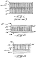
FIG. 1 is a schematic cross-sectional view of a prior acoustic panel having a septum; -
FIG. 2 is a schematic cross-sectional view of an acoustic panel in accordance with one preferred embodiment of the invention; -
FIG. 3 is a schematic cross-sectional view of an acoustic panel for treating a shroud of a mixer nozzle for a series of tests conducted to assess the effectiveness of acoustic treatment in accordance with the invention; -
FIG. 4 is a cross-sectional view of the nozzle used in the series of tests; -
FIG. 4A is a cross-sectional view of the nozzle along theline 4A-4A ofFIG. 4 ; -
FIG. 4B is a cross-sectional view of the nozzle along theline 4B-4B ofFIG. 4 ; -
FIG. 4C is a cross-sectional view of the nozzle along theline 4C-4C ofFIG. 4 ; and -
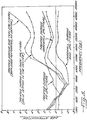
FIG. 5 is a plot of test results comparing the noise attenuation achieved for the nozzle with various configurations of acoustic treatment. - The present invention now will be described more fully hereinafter with reference to the accompanying drawings, in which preferred embodiments of the invention are shown. This invention may, however, be embodied in many different forms and should not be construed as limited to the embodiments set forth herein; rather, these embodiments are provided so that this disclosure will be thorough and complete, and will fully convey the scope of the invention to those skilled in the art. Like numbers refer to like elements throughout.
-
FIG. 1 shows a prioracoustic panel 10 such as disclosed inU.S. Patent Nos. 4,265,955 and4,257,998 . Thepanel 10 includes a solid plate orseptum 12, a layer ofhoneycomb material 14 bonded to each of the opposite faces of theseptum 12, and aface sheet 16 bonded to the outer surface of eachhoneycomb layer 14. Eachface sheet 16 comprises a perforated plate. -
FIG. 2 depicts anacoustic panel 20 in accordance with the present invention. Thepanel 20 includes acore layer 22 of porous material such as honeycomb, and a pair offace sheets 24 bonded to each of the opposite faces of thecore layer 22. Thecore layer 22 includes a plurality of through openings that extend from one face of the core layer to the opposite face thereof. Thus, in the illustrated preferred embodiment where thecore layer 22 is a honeycomb material, the cells of the honeycomb define the through openings. Alternatively, thecore layer 22 can comprise a porous bulk absorber material having pores that communicate from one face of the core layer to the other. - Each
face sheet 24 comprises aperforated plate 26 and a porous sheet 28 of fibrous cloth. In the preferred embodiment, the sheets 28 comprise metal cloth, but in some applications it may be possible to form the sheets 28 from a material other than metal. A suitable metal cloth can be, for example, a woven wire material or a metal felt material. The porous fibrous sheets 28 are characterized by a multiplicity of small holes defined between the fibers of the sheets. These holes communicate with the perforations in theperforated plates 26, which in turn communicate with the cells or through openings of thecore layer 22. - Generally, the thickness of the
core layer 22 will be greater than that of aface sheet 24. The thickness and other physical characteristics of each of the various layers of thepanel 20 are generally dependent on the acoustic, strength, and weight objectives for the panel. It is frequently desired to "tune" the panel to provide noise attenuation at a particular frequency or over a particular range of frequencies. As known in the art, where a honeycomb core layer is used in an acoustic panel, the sizes of the cells can be selected to tune the core layer to a particular frequency or range of frequencies. With regard to theperforated plates 26, their primary function is to provide structural rigidity to thepanel 20, and hence the thickness and percent open area of theperforated plates 26 must be selected so as to achieve the desired strength for the panel. As a general rule, it is desirable for theperforated plates 26 to have as large an open area as can be tolerated from a strength standpoint so that theplates 26 will have a relatively small acoustic effect in comparison with that of the fibrous sheets 28. For example, theplates 26 can have about a 20 percent to about 40 percent open area. It will also be appreciated that where the desired strength of the panel can be achieved with thecore layer 22 and fibrous sheets 28 alone, theperforated plates 26 can be omitted and the fibrous sheets 28 can be directly bonded to thecore layer 22 in a similar way as taught byUS Patent No. 4,111,081 . - The
panel 20 is formed by suitably bonding the various layers to one another. This can be accomplished by welding or brazing the layers together where they are constructed of metal. Alternatively, such metal layers can be attached together by a sintering type technique in which the layers are assembled together and the assembly is placed in an oven to heat the assembly while pressure is applied to the assembly. A still further alternative is to join the layers together with a suitable adhesive. - The fibrous sheets 28 provide noise attenuation through viscous losses that occur through the sheets. The optimum or advantageous acoustic resistance of the fibrous sheets 28 in general is a function of the flow dynamic, thermodynamic, fluid, and material properties. Mathematical modeling of the
acoustic panel 20 for a high-Mach number, high-pressure, and high-temperature flow suggests that relatively low acoustic resistance for each of the sheets 28 is desirable, for example, about 10 Rayls at 20 cm/sec. In other applications, the optimum acoustic resistance of each of the fibrous sheets 28 may be different, but it is expected that in general an optimum acoustic resistance for most applications will be from about 5 Rayls to about 300 Rayls at 20 cm/sec. - The present invention was developed in conjunction with development activities on the High Speed Civil Transport (HSCT) project conducted in cooperation with NASA. One concept for the propulsion package for the HSCT utilizes turbojet engines that are fitted with mixer-ejector nozzles for attenuating noise associated with the mixing of the engine exhaust plumes. The assignee of the present application has developed a near-fully mixed (NFM) nozzle for application to the HSCT. It is contemplated that the NFM nozzle will require acoustic treatment in order to meet overall noise goals for the propulsion package.
- Accordingly, the panel of the present invention was developed for placement in the NFM nozzle duct. An experimental test program was conducted to determine the noise attenuation performance of several configurations of acoustic treatment. One of the objectives of the test was to compare the noise attenuation performance of conventional acoustic panels having a septum to that of the no-septum panels of the present invention.
-
FIG. 4 shows a cross-sectional view of the NFM nozzle test model. The NFM nozzle includes alobed aspirator section 30 having a plurality of full-penetration, aspirated flow passages 32 spaced circumferentially around the nacelle and alternating withprimary flow passages 34, as best seen in the cross-sectional view ofFIG. 4A . The inlets to the aspirated flow passages 32 are flush with the outer nacelle. Under takeoff and landing operating conditions of the actual engine, the aspirated flow passages 32 would be open when noise suppression is desired, and at other conditions the inlets to these passages could be closed by inlet doors (not shown). The exits of theprimary flow passages 34 resemble a plurality of rectangular plug nozzles each having a radial strut/plug 36 located directly behind theflow passage 34. The nozzle flow passages are convergent-divergent as a result of the wedge-shaped contour of theplugs 36. Theplugs 36 are pinned to acenterbody 38. - The NFM nozzle also includes a mixing
nozzle 40 in which acoustic treatment is incorporated. The mixingnozzle 40 includes anouter shroud 42 of generally cylindrical form and a plurality of circumferentially spacedradial splitters 44 that extend radially inwardly from theshroud 42. As further explained below, in the series of tests acoustic panels were applied to theshroud 42 alone, thesplitters 44 alone, and to both the shroud and the splitters, to determine the effect on noise attenuation of treating the shroud and/or splitters. - The NFM nozzle was tested in Boeing's Low-Speed Aeroacoustic Facility (LSAF) consisting of a free-jet wind tunnel having its test section in an anechoic chamber. The chamber was fitted with a pair of traversing near-sideline microphones and with 16 pole-mounted far-sideline microphones.
- Various configurations were tested. One configuration had a
hardwall shroud 42 andhardwall splitters 44. Another configuration hadhardwall splitters 44 but theshroud 42 was treated with an acoustic panel 50 as shown inFIG. 3 . The shroud panel 50 comprised a honeycomb core 52 with aface sheet 54 on one side thereof formed of aperforated plate 56 and a metal cloth sheet 58, and asolid backing sheet 60 on the opposite side of the core 52. The thickness of the core 52 was 0.15 inch, that of theface sheet 54 was 0.03 inch, and that of thebacking sheet 60 was 0.15 inch. Theface sheet 54 formed the surface of the shroud panel 50 that faced into the nozzle. Theperforated plate 56 had a 31 percent open area with holes of 0.055 inch diameter. The metal cloth sheet 58 comprised a woven wire having an acoustic resistance of 10 Rayls at 20 cm/sec, with a 2.6 non-linearity factor measured at an airflow of 200 cm/sec versus 20 cm/sec. - Another tested configuration had a treated shroud as described above, but the
splitters 44 were omitted. Yet another configuration had a treated shroud, andsplitters 44 formed by conventionalacoustic panels 10 having a solid septum as shown inFIG. 1 . The thickness of each of the honeycomb core layers 14 was 0.15 inch, and theperforated plates 16 each had a 31 percent open area with 0.055 inch diameter holes. The core layers 14 had honeycomb cells of 1/8-inch diameter. - A final configuration tested had a treated shroud, and
splitters 44 formed byacoustic panels 20 in accordance with the invention as shown inFIG. 2 . Thecore 22 was a honeycomb of 0.15 inch thickness with 1/8-inch diameter cells (i.e., identical to one of the honeycomb layers 14 of the conventional panel with septum). Theface sheets 24 comprisedperforated plates 26 having a 31 percent open area with 0.055 inch diameter holes, and metal cloth sheets 28 comprising a woven wire with an acoustic resistance of 10 Rayls at 20 cm/sec, with a 2.6 non-linearity factor measured at an airflow of 200 cm/sec versus 20 cm/sec. -
FIG. 5 depicts test results for all of these various nozzle configurations. The noise attenuation relative to a baseline configuration (hardwall shroud with no splitters) is plotted as a function of frequency for a location 90° from the longitudinal axis of the nozzle. Of particular note is the fact that the thin splitters designed in accordance with the invention provide greater noise attenuation than that provided by the thick splitters having a septum. The thin splitters also provide the additional benefits of presenting significantly less blockage than the thick splitters and being substantially lighter in weight than the thick splitters. It will also be noted that disposing treated splitters in the nozzle duct provides a noise attenuation benefit relative to the configuration without splitters. - Many modifications and other embodiments of the invention will come to mind to one skilled in the art to which this invention pertains having the benefit of the teachings presented in the foregoing descriptions and the associated drawings. Therefore, it is to be understood that the invention is not to be limited to the specific embodiments but to be defined by the scope of the appended claims.
Claims (17)
- An acoustic sandwich panel for attenuating noise from noise sources on either side of the panel, comprising:- a core layer (22) with no septum having opposite faces, and including a plurality of through openings that extend from one face of the core layer (22) to the opposite face thereof; and- a face sheet (24) attached to each of the opposite faces of the core layer (22) so as to sandwich the core layer (22) therebetween, each face sheet (24) comprising a perforated plate (26) and at least a porous sheet (28) of fibrous cloth defining an outer surface of the face sheet (24).
- The acoustic sandwich panel of claim 1, wherein the porous fiber sheets (28) are characterized by a multiplicity of small holes, which communicate with the perforations in the perforated plates (26), which in turn communicate with the cells or through openings of the core layer (22).
- The acoustic sandwich panel of claim 1 or 2, wherein the perforated plate (26) comprises a structural layer that is bonded to the core (22) for providing structural rigidity to the panel, the structural layers having openings extending through a thickness thereof and being configured to have a relatively small acoustic effect compared to that of the sheets of fibrous cloth.
- The acoustic sandwich panel of claim 3, wherein the structural layers comprise perforated metal plates.
- The acoustic sandwich panel of claim 1, wherein the core comprises a honeycomb material.
- The acoustic sandwich panel of claim 5, wherein the honeycomb is formed of metal.
- The acoustic sandwich panel according to any of the foregoing claims, each face sheet (24) including a perforated metal plate (26) bonded to the core layer (22) and a sheet (28) of metal cloth attached to an outer surface of the perforated plate (26).
- The acoustic sandwich panel according to any of the foregoing claims, wherein each perforated metal plate has an open area of about 20 to 40 percent.
- The acoustic sandwich panel according to any of the foregoing claims, wherein each cloth sheet has an acoustic resistance of about 5 to 300 Rayls.
- The acoustic sandwich panel according to any of the foregoing claims, wherein the cloth sheets comprise sheets of woven wire.
- The acoustic sandwich panel of any of claims 1-9, wherein the cloth sheets comprise sheets of metal felt.
- An apparatus for suppressing noise in a nozzle having a duct, comprising:- a plurality of radial splitters (44) disposed in the duct spaced about a circumference thereof, each radial splitter (44) comprising:- a core layer (22) with no septum having opposite faces, and including a plurality of through openings that extend from one face of the core layer (22) to the opposite face thereof; and- a face sheet (24) attached to each of the opposite faces of the core layer (22) so as to sandwich the core layer (22) therebetween, each face sheet (24) comprising a perforated plate (26) and at least a porous sheet (28) of fibrous cloth defining an outer surface of the face sheet (24).
- The apparatus of claim 12, wherein the perforated plate (26) comprises a structural layer that is bonded to the core (22) for providing structural rigidity to the panel, the structural layers having openings extending through a thickness thereof and being configured to have a relatively small acoustic effect compared to that of the sheets of fibrous cloth.
- An apparatus according to claim 12 or 13, comprising a panel according to any of claims 1-11.
- A method for suppressing noise in a duct of a nozzle, comprising;- disposing at least one panel-shaped splitter (44) in the duct such that flow occurs over both of two opposite faces of the splitter (44), the splitter comprising:- a core layer (22) with no septum having opposite faces, and including a plurality of through openings that extend from one face of the core layer (22) to the opposite face thereof; and- a face sheet (24) attached to each of the opposite faces of the core layer (22) so as to sandwich the core layer (22) therebetween, each face sheet (24) comprising a perforated plate (26) and at least a porous sheet (28) of fibrous cloth defining an outer surface of the face sheet (24).
- The method of claim 15, wherein the splitter is oriented generally radially in the duct.
- The method of claim 16, wherein a plurality of said splitters (44) are disposed in the duct so as to be oriented generally radially and spaced apart circumferentially.
Applications Claiming Priority (2)
| Application Number | Priority Date | Filing Date | Title |
|---|---|---|---|
| US672480 | 2000-09-28 | ||
| US09/672,480 US6509081B1 (en) | 2000-09-28 | 2000-09-28 | No-septum acoustic sandwich panel, and apparatus and method for suppressing noise in a nozzle |
Publications (2)
| Publication Number | Publication Date |
|---|---|
| EP1193682A1 EP1193682A1 (en) | 2002-04-03 |
| EP1193682B1 true EP1193682B1 (en) | 2018-11-28 |
Family
ID=24698725
Family Applications (1)
| Application Number | Title | Priority Date | Filing Date |
|---|---|---|---|
| EP01203262.9A Expired - Lifetime EP1193682B1 (en) | 2000-09-28 | 2001-08-29 | Acoustic sandwich panel with no septum and apparatus and method for suppressing noise in a turbojet nozzle |
Country Status (3)
| Country | Link |
|---|---|
| US (1) | US6509081B1 (en) |
| EP (1) | EP1193682B1 (en) |
| JP (1) | JP4959886B2 (en) |
Families Citing this family (30)
| Publication number | Priority date | Publication date | Assignee | Title |
|---|---|---|---|---|
| DE102005048156B9 (en) * | 2005-10-06 | 2010-08-12 | Dorma Gmbh + Co. Kg | Mobile partition |
| US7540354B2 (en) * | 2006-05-26 | 2009-06-02 | United Technologies Corporation | Micro-perforated acoustic liner |
| JP2009062977A (en) * | 2007-08-15 | 2009-03-26 | Rohr Inc | Linear acoustic liner |
| CN102089801B (en) * | 2008-05-22 | 2013-05-29 | 3M创新有限公司 | Multilayer sound absorbing structure comprising mesh layer |
| FR2933224B1 (en) * | 2008-06-25 | 2010-10-29 | Aircelle Sa | ACCOUSTIC PANEL FOR EJECTION TUBE |
| JP5305074B2 (en) * | 2008-07-24 | 2013-10-02 | 株式会社Ihi | Channel structure |
| US8113767B2 (en) * | 2008-09-15 | 2012-02-14 | Hamilton Sundstrand Corporation | Auxiliary power unit inlet duct with acoustic silencing |
| CN101936061A (en) * | 2009-05-22 | 2011-01-05 | 塞梅潘工业公司 | Structure floor panel and the flooring structure that is combined with this floor panel |
| KR101821825B1 (en) * | 2009-06-25 | 2018-01-24 | 쓰리엠 이노베이티브 프로퍼티즈 컴파니 | Sound barrier for audible acoustic frequency management |
| US9079674B1 (en) * | 2009-09-18 | 2015-07-14 | Blue Origin, Llc | Composite structures for aerospace vehicles, and associated systems and methods |
| CN101944357A (en) * | 2010-08-27 | 2011-01-12 | 张宇 | Multi-module impedance compound sound insulation plate and manufacturing method thereof |
| US9897111B2 (en) | 2011-05-20 | 2018-02-20 | Dyna-Tech Sales Corporation | Aspirating induction nozzle with flow transition |
| US8974272B2 (en) | 2011-05-20 | 2015-03-10 | Dyna-Tech Sales Corporation | Aspirating induction nozzle |
| US8696843B1 (en) | 2012-09-06 | 2014-04-15 | The Boeing Company | Repair of acoustically treated structures |
| US9371836B2 (en) | 2012-10-25 | 2016-06-21 | Dyna-Tech Sales Corporation | Mixed flow fan assembly |
| CN103032381B (en) * | 2013-01-05 | 2015-09-02 | 华北电力大学(保定) | For reducing the casing of noise of axial flow fan |
| CN103032379B (en) * | 2013-01-05 | 2015-05-13 | 华北电力大学(保定) | Low-noise centrifugal ventilator casing |
| US10036403B2 (en) * | 2013-03-20 | 2018-07-31 | Dyna-Tech Sales Corporation | Variable volume induction nozzle |
| CN105492196A (en) * | 2013-07-15 | 2016-04-13 | 阿姆斯特郎世界工业公司 | Acoustical structure |
| US8820477B1 (en) | 2013-07-29 | 2014-09-02 | The Boeing Company | Acoustic panel |
| US9643392B2 (en) | 2013-07-29 | 2017-05-09 | The Boeing Company | Septumization of honeycomb sandwiches |
| US10060442B2 (en) | 2013-10-24 | 2018-08-28 | Dyna-Tech Sales Corporation | Mixed flow fan assembly |
| US9693166B2 (en) | 2014-06-24 | 2017-06-27 | The Boeing Company | Automated production of acoustic structures |
| US9931825B2 (en) | 2014-07-09 | 2018-04-03 | The Boeing Company | Septumization of cellular cores |
| CN105161089B (en) * | 2015-06-17 | 2019-10-15 | 成都斯铂润音响设备有限公司 | A kind of sound absorber |
| US10308368B2 (en) * | 2015-10-30 | 2019-06-04 | General Electric Company | Turbofan engine and method of reducing air flow separation therein |
| US20220093072A1 (en) * | 2018-11-30 | 2022-03-24 | Ashmere Holdings Pty Ltd | Acoustic Absorption |
| FR3101723B1 (en) * | 2019-10-08 | 2022-07-22 | Safran Nacelles | Acoustic attenuation panel for low frequency waves |
| CN112199787B (en) * | 2020-09-24 | 2022-04-15 | 北京航空航天大学 | Elliptical partition plate nozzle shaping method for increasing acoustic energy dissipation |
| US11845699B2 (en) | 2021-09-07 | 2023-12-19 | Blue Origin, Llc | Methods for manufacturing coated composite materials |
Family Cites Families (37)
| Publication number | Priority date | Publication date | Assignee | Title |
|---|---|---|---|---|
| US3502171A (en) | 1968-05-31 | 1970-03-24 | Boeing Co | Composite laminar structure for noise attenuation of fast moving gas streams,and method of making the same |
| US3647021A (en) * | 1970-06-22 | 1972-03-07 | Rohr Corp | Sound suppression system |
| US3821999A (en) | 1972-09-05 | 1974-07-02 | Mc Donnell Douglas Corp | Acoustic liner |
| US3819007A (en) | 1973-04-27 | 1974-06-25 | Lockheed Aircraft Corp | Controllable laminar sound absorptive structure |
| US4254171A (en) | 1975-08-13 | 1981-03-03 | Rohr Industries, Inc. | Method of manufacture of honeycomb noise attenuation structure and the resulting structure produced thereby |
| US4111081A (en) | 1976-01-02 | 1978-09-05 | The Boeing Company | Low non-linearity factor sound attenuating laminate |
| US4001473A (en) | 1976-02-19 | 1977-01-04 | Rohr Industries, Inc. | Sound attenuating structural honeycomb sandwich material |
| US4257998A (en) | 1978-05-01 | 1981-03-24 | The Boenig Company | Method of making a cellular core with internal septum |
| US4265955A (en) | 1978-05-01 | 1981-05-05 | The Boeing Company | Honeycomb core with internal septum and method of making same |
| US4235303A (en) | 1978-11-20 | 1980-11-25 | The Boeing Company | Combination bulk absorber-honeycomb acoustic panels |
| US4292356A (en) | 1979-07-06 | 1981-09-29 | Rohr Industries, Inc. | Method of manufacturing of honeycomb noise attenuation structure and the structure resulting from the method |
| US4539244A (en) | 1979-08-06 | 1985-09-03 | Rohr Industries, Inc. | Honeycomb noise attenuation structure |
| US4522859A (en) * | 1979-10-29 | 1985-06-11 | Rohr Industries, Inc. | Method of manufacture of honeycomb noise attenuation structure for high temperature applications |
| US4291080A (en) | 1980-03-31 | 1981-09-22 | Vought Corporation | Sound attenuating structural panel |
| US4384020A (en) | 1980-12-22 | 1983-05-17 | Rohr Industries, Inc. | Honeycomb noise attenuating structures |
| JPS57168099A (en) * | 1981-04-10 | 1982-10-16 | Hitachi Ltd | Muffler for jet fan |
| US4421201A (en) | 1981-09-29 | 1983-12-20 | The Boeing Company | High efficiency broadband acoustic resonator and absorption panel |
| JPS58209791A (en) * | 1982-05-19 | 1983-12-06 | シヨート・ブラザース・ピーエルシー | Front sheet for sound absorbing panel, manufacture thereof and acoustic energy attenuator therewith |
| JPS58222838A (en) * | 1982-06-19 | 1983-12-24 | 日本無機株式会社 | Cored fiber board and its manufacture |
| US4433021A (en) | 1982-09-22 | 1984-02-21 | Rohr Industries, Inc. | Sound attenuation sandwich panel including barrier material for corrosion control |
| JPS6160946A (en) * | 1984-09-03 | 1986-03-28 | 新日本コア株式会社 | Panel structure having sound blocking property |
| US4600619A (en) | 1984-12-31 | 1986-07-15 | The Boeing Company | Continuously wound filament structure for use in noise attenuation element |
| JPS61259000A (en) * | 1985-05-09 | 1986-11-17 | Matsushita Seiko Co Ltd | Muffling elbow for axial blower |
| US5151311A (en) | 1987-11-02 | 1992-09-29 | Grumman Aerospace Corporation | Acoustic attenuating liner and method of making same |
| GB8817669D0 (en) | 1988-07-25 | 1988-09-01 | Short Brothers Ltd | Means for attenuating sound energy |
| US4990391A (en) * | 1989-02-03 | 1991-02-05 | Rohr Industries, Inc. | Reticulated core to perforate sheet bonding and galvanic barrier |
| US5180619A (en) | 1989-12-04 | 1993-01-19 | Supracor Systems, Inc. | Perforated honeycomb |
| GB9101353D0 (en) | 1991-01-22 | 1991-03-06 | Short Brothers Plc | Noise attenuation panel |
| DE4131394C2 (en) | 1991-09-20 | 1996-12-05 | Pelz Ernst Empe Werke | Sound Insulation |
| US5445861A (en) | 1992-09-04 | 1995-08-29 | The Boeing Company | Lightweight honeycomb panel structure |
| FR2710874B1 (en) | 1993-10-04 | 1995-12-22 | Aerospatiale | Rigid, self-supporting sheet material for acoustic attenuation and panel made of such material. |
| DE4422585C1 (en) * | 1994-06-28 | 1995-10-05 | Freudenberg Carl Fa | Air noise absorbing form part |
| JPH08151999A (en) * | 1994-11-29 | 1996-06-11 | Hitachi Ltd | Blower device with silencer |
| JPH08190385A (en) * | 1995-01-07 | 1996-07-23 | Wakamatsu Netsuren Kk | Sound absorbing material and sound absorbing structural body |
| FR2735064B1 (en) | 1995-06-09 | 1997-08-29 | Aerospatiale | PROCESS FOR PRODUCING MICROPOROUS SKIN IN COMPOSITE MATERIAL |
| JP2931564B2 (en) * | 1997-05-14 | 1999-08-09 | 三郎 野澤 | Structure including honeycomb structure and method for manufacturing the same |
| US5912442A (en) * | 1997-07-02 | 1999-06-15 | Trw Inc. | Structure having low acoustically-induced vibration response |
-
2000
- 2000-09-28 US US09/672,480 patent/US6509081B1/en not_active Expired - Lifetime
-
2001
- 2001-08-29 EP EP01203262.9A patent/EP1193682B1/en not_active Expired - Lifetime
- 2001-09-26 JP JP2001293692A patent/JP4959886B2/en not_active Expired - Lifetime
Non-Patent Citations (1)
| Title |
|---|
| None * |
Also Published As
| Publication number | Publication date |
|---|---|
| JP2002189475A (en) | 2002-07-05 |
| EP1193682A1 (en) | 2002-04-03 |
| JP4959886B2 (en) | 2012-06-27 |
| US6509081B1 (en) | 2003-01-21 |
Similar Documents
| Publication | Publication Date | Title |
|---|---|---|
| EP1193682B1 (en) | Acoustic sandwich panel with no septum and apparatus and method for suppressing noise in a turbojet nozzle | |
| US4759513A (en) | Noise reduction nacelle | |
| US7124856B2 (en) | Acoustic liner for gas turbine engine | |
| EP2013466B1 (en) | Sound-absorbing exhaust nozzle center plug | |
| US10563578B2 (en) | Acoustic liners and method of shaping an inlet of an acoustic liner | |
| EP3564508B1 (en) | Aircraft propulsion system assembly including one or more acoustic panels | |
| GB2527899A (en) | Noise attenuating lipskin assembly and methods of assembling the same | |
| US9630702B2 (en) | Noise attenuation for an open rotor aircraft propulsion system | |
| EP3062308B1 (en) | Sound attenuation using a cellular core | |
| EP3281192B1 (en) | Acoustic liner and method of constructing an acoustic liner | |
| Bielak et al. | Advanced turbofan duct liner concepts | |
| US20100213002A1 (en) | Fibrous materials, noise suppression materials, and methods of manufacturing noise suppression materials | |
| US20210215122A1 (en) | Output cone of an aircraft propulsive assembly forming an acoustic treatment system with at least two degrees of freedom | |
| US20240101264A1 (en) | Reduced bulk acoustic treatment panel for a turbojet engine | |
| EP4159997A2 (en) | Low-frequency acoustic center body | |
| US10723476B2 (en) | Ring of turbojet vanes including an acoustic treatment structure | |
| CA2893336C (en) | Inner bypass duct with acoustic and fireproof layers | |
| US20200392899A1 (en) | Acoustic treatment for aircraft engine | |
| US20230003176A1 (en) | Method for manufacturing a structure with cellular cores for a turbojet nacelle | |
| US11591958B2 (en) | Turbofan engine with acoustic treatment | |
| US20240159203A1 (en) | Low-frequency acoustic center body | |
| WO2020225397A1 (en) | Noise-attenuating device and method of manufacture | |
| Massey et al. | Computational analysis of the effect of porosity on shock cell strength at cruise |
Legal Events
| Date | Code | Title | Description |
|---|---|---|---|
| PUAI | Public reference made under article 153(3) epc to a published international application that has entered the european phase |
Free format text: ORIGINAL CODE: 0009012 |
|
| AK | Designated contracting states |
Kind code of ref document: A1 Designated state(s): AT BE CH CY DE DK ES FI FR GB GR IE IT LI LU MC NL PT SE TR Kind code of ref document: A1 Designated state(s): DE FR GB |
|
| AX | Request for extension of the european patent |
Free format text: AL;LT;LV;MK;RO;SI |
|
| 17P | Request for examination filed |
Effective date: 20021001 |
|
| AKX | Designation fees paid |
Free format text: DE FR GB |
|
| 17Q | First examination report despatched |
Effective date: 20090217 |
|
| GRAP | Despatch of communication of intention to grant a patent |
Free format text: ORIGINAL CODE: EPIDOSNIGR1 |
|
| INTG | Intention to grant announced |
Effective date: 20180618 |
|
| GRAS | Grant fee paid |
Free format text: ORIGINAL CODE: EPIDOSNIGR3 |
|
| GRAA | (expected) grant |
Free format text: ORIGINAL CODE: 0009210 |
|
| AK | Designated contracting states |
Kind code of ref document: B1 Designated state(s): DE FR GB |
|
| REG | Reference to a national code |
Ref country code: GB Ref legal event code: FG4D |
|
| REG | Reference to a national code |
Ref country code: DE Ref legal event code: R096 Ref document number: 60151018 Country of ref document: DE |
|
| REG | Reference to a national code |
Ref country code: DE Ref legal event code: R097 Ref document number: 60151018 Country of ref document: DE |
|
| PLBE | No opposition filed within time limit |
Free format text: ORIGINAL CODE: 0009261 |
|
| STAA | Information on the status of an ep patent application or granted ep patent |
Free format text: STATUS: NO OPPOSITION FILED WITHIN TIME LIMIT |
|
| 26N | No opposition filed |
Effective date: 20190829 |
|
| PGFP | Annual fee paid to national office [announced via postgrant information from national office to epo] |
Ref country code: GB Payment date: 20200827 Year of fee payment: 20 Ref country code: FR Payment date: 20200825 Year of fee payment: 20 Ref country code: DE Payment date: 20200827 Year of fee payment: 20 |
|
| REG | Reference to a national code |
Ref country code: DE Ref legal event code: R071 Ref document number: 60151018 Country of ref document: DE |
|
| REG | Reference to a national code |
Ref country code: GB Ref legal event code: PE20 Expiry date: 20210828 |
|
| PG25 | Lapsed in a contracting state [announced via postgrant information from national office to epo] |
Ref country code: GB Free format text: LAPSE BECAUSE OF EXPIRATION OF PROTECTION Effective date: 20210828 |