EP1193430A2 - Ventil, insbesondere Heizkörperventil - Google Patents
Ventil, insbesondere Heizkörperventil Download PDFInfo
- Publication number
- EP1193430A2 EP1193430A2 EP01203527A EP01203527A EP1193430A2 EP 1193430 A2 EP1193430 A2 EP 1193430A2 EP 01203527 A EP01203527 A EP 01203527A EP 01203527 A EP01203527 A EP 01203527A EP 1193430 A2 EP1193430 A2 EP 1193430A2
- Authority
- EP
- European Patent Office
- Prior art keywords
- valve
- valve seat
- valve element
- valve according
- chamber
- Prior art date
- Legal status (The legal status is an assumption and is not a legal conclusion. Google has not performed a legal analysis and makes no representation as to the accuracy of the status listed.)
- Granted
Links
- 239000012530 fluid Substances 0.000 claims description 6
- 239000012528 membrane Substances 0.000 claims description 5
- 238000007789 sealing Methods 0.000 claims description 5
- 230000000284 resting effect Effects 0.000 claims description 2
- 239000013536 elastomeric material Substances 0.000 claims 1
- XLYOFNOQVPJJNP-UHFFFAOYSA-N water Substances O XLYOFNOQVPJJNP-UHFFFAOYSA-N 0.000 abstract description 21
- 239000013013 elastic material Substances 0.000 description 4
- 239000007788 liquid Substances 0.000 description 4
- 230000000694 effects Effects 0.000 description 3
- 238000010438 heat treatment Methods 0.000 description 3
- 229920001971 elastomer Polymers 0.000 description 2
- 239000005060 rubber Substances 0.000 description 2
- 238000004873 anchoring Methods 0.000 description 1
- 238000013461 design Methods 0.000 description 1
- 230000002996 emotional effect Effects 0.000 description 1
- 238000002474 experimental method Methods 0.000 description 1
- 239000008236 heating water Substances 0.000 description 1
- 238000004519 manufacturing process Methods 0.000 description 1
- 239000000463 material Substances 0.000 description 1
- 238000000034 method Methods 0.000 description 1
- 238000012797 qualification Methods 0.000 description 1
- 229920003051 synthetic elastomer Polymers 0.000 description 1
- 239000005061 synthetic rubber Substances 0.000 description 1
- 238000012549 training Methods 0.000 description 1
Images


Classifications
-
- F—MECHANICAL ENGINEERING; LIGHTING; HEATING; WEAPONS; BLASTING
- F16—ENGINEERING ELEMENTS AND UNITS; GENERAL MEASURES FOR PRODUCING AND MAINTAINING EFFECTIVE FUNCTIONING OF MACHINES OR INSTALLATIONS; THERMAL INSULATION IN GENERAL
- F16K—VALVES; TAPS; COCKS; ACTUATING-FLOATS; DEVICES FOR VENTING OR AERATING
- F16K1/00—Lift valves or globe valves, i.e. cut-off apparatus with closure members having at least a component of their opening and closing motion perpendicular to the closing faces
- F16K1/32—Details
- F16K1/34—Cutting-off parts, e.g. valve members, seats
- F16K1/36—Valve members
Definitions
- the invention relates to a valve, in particular a radiator valve, with a housing that has an inlet connection and has an outflow connection, the Flow path between inflow connection and outflow connection a shut-off device is arranged, the a valve seat and a valve element interacting therewith has, the valve element in a Valve chamber is movable.
- Such a valve designed as a radiator valve is known from WO 99/22282.
- valve it looks different if the valve is connected incorrectly will, i.e. the feed line of a heating system is connected to the outlet port. In this case the water flows over the valve element to the valve seat and from there into the inlet connection. If the valve closes, the valve element is closed towards the valve seat emotional. If the gap between the valve element and the valve seat falls below a certain size, the valve element closes abruptly, which also sudden increase in pressure at the outlet connection Has. This increase in pressure manifests itself in a water hammer, which not only results in unpleasant noises has, but also cause damage to the pipe system can. This water hammer can also be caused by trigger an external pulse, for example through another valve that suddenly closes or opens, a pump that starts or stops, or other. These causes, which have not yet been fully clarified are particularly critical when the valve is incorrectly installed.
- the invention has for its object a valve to be able to operate independently of the flow direction.
- shut-off device has a stop aid device that the valve element resting on the valve seat or a Part of it under further movement in the closing direction Increasing the volume of the valve chamber allowed.
- valve element or a part thereof larger volume of the valve chamber (or a related one Space) in which the inflowing Water without increasing pressure, can evade.
- This enlargement need not be excessive.
- the volume released by the valve element is sufficient to absorb the inflowing liquid, so that the pressure peaks which have been observed up to now have been omitted. Accordingly, you can use the radiator valve now operate independently of the direction of flow, no longer has to take care when installing that the inlet connection with the inlet line and connects the outlet connection to the drain line.
- the anchoring device is formed by a spring arrangement which the valve element and / or is assigned to the valve seat.
- the spring arrangement ensures that the evasive movement, which the valve element immediately after impact carried out on the valve seat, undone again becomes. This also stands for the next closing process the desired route for the evasive movement to disposal. In addition, after each closing a defined state is restored.
- the Spring arrangement can also be used to the evasive movement to the level of the differential pressure between the outflow connection and the inflow connection adapt. If these differential pressures only are small, such an evasive movement is not required and in some cases even annoying. For example it could cause a radiator is continuously "switched on", i.e. flowed through by water even if this is not intended. With larger differential pressures, however, the evasive movement is then controlled by the spring assembly possible.
- a valve element is preferably deformable Zone trained. This deformable zone then serves as an anchor device or as part of it. If the valve element collides with the valve seat, then results from touching the valve element with the valve seat the closed state of the radiator valve. However, the valve element can be moved on by deforming the deformable zone. In order to the valve element can reduce its volume and become a Release the corresponding volume in the valve chamber. The deformation is elastic, i.e. the deformable Zone acts as a spring and takes its original shape back on later.
- deformable zone Valve seat is adjacent.
- the increase in volume of the The valve chamber is then the largest.
- the deformable zone is preferably an annular wall educated. This is a relatively simple constructive one Possibility to create a deformable zone.
- the ring wall a rubber-elastic material is formed.
- This Material can be easily deformed, but it wears off the absence of those caused by the pressure surge Forces back to its original shape. Furthermore you can use the elastic material for one Ensure the radiator valve is tight.
- the valve element preferably has one with a compressible fluid-filled pressure chamber that of the valve chamber separated by a deformable membrane is.
- the membrane can, for example, by the Ring wall be formed. Basically there is one Possibility of forming the pressure space simply by that you cover the ring wall.
- the compressible fluid can be squeezed, but expands again out when the external forces weaken, so that the valve element regains its original shape.
- the pressure room can also be used on others Place of the valve element may be arranged. In this Fall does not move the valve element in the area of the valve seat, but it just moves part of the valve element, namely the membrane, the is deformed into the pressure chamber. That too is however, it is possible to increase the volume in the valve chamber to effect.
- valve element on its Valve seat facing side one of a deformable Covered escape area on the wall with the Valve chamber connected via a channel in the valve element stands.
- the wall can also move if that Valve element abuts the valve seat, still in the closing direction deform further. It then deforms, so to speak into the opening surrounded by the valve seat is.
- This also increases a volume, which also includes the valve chamber is connected via the channel in the valve element. The inflowing liquid can then dodge into this volume, causing the water hammer is mitigated or even avoided.
- valve seat is arranged on a valve seat support is supported by a spring in the housing.
- the valve element comes into contact with the valve seat the radiator valve is closed.
- the valve element can, however, together with the valve seat support still further in the same direction as move when closing, increasing the volume of the valve chamber is increased accordingly to a pressure surge catch.
- valve seat support one Has stop that under the action of the spring a counter stop in the housing. Stop and Counter stop thus define the rest position of the valve seat carrier and thus the position of the valve seat.
- the stop is preferably formed by a ring, which is arranged in a groove in the valve seat carrier and protrudes radially from this groove. This makes it easier manufacturing. You can use the ring for example form as a spring ring or snap ring that is compressed when the valve seat carrier is in the housing is used. There he can expand and come then to lie behind the counter stop.
- sealing ring arranged between the valve seat support and the Housing a sealing ring arranged. This sealing ring secures that no radiator fluid between the Valve seat support and the housing on the through valve element and valve seat formed sealing point can.
- Fig. 1 shows a radiator valve 1 with a housing 2, which has an inflow connection 3 and an outflow connection 4 has. Between the inflow connection 3 and the outflow port 4 is a shut-off device 5 arranged, which has a valve element 6 which of a valve lifter 7 can be actuated and that with a Valve seat 8 interacts.
- the valve lifter 7 is in known per se and therefore not shown in detail Way via an actuating pin 9 of a thermostat attachment or a similar actuator actuated.
- a spring 10 thus acts on the valve lifter 7 that the valve element 6 moves away from the valve seat 8 becomes.
- Fig. 2 shows an enlarged view of the valve element 6 on the valve seat 8. It can be seen that the valve element 6 in the direction of the valve seat 8 ends in an annular wall 11, which is a deformable Zone 12 forms.
- the ring wall has a length in the area from about 0.8 to 2 mm, preferably about 1 mm and a radial thickness in the range of approximately 0.25 to 0.4 mm, preferably about 0.3 mm. It is like that too remaining valve element 6 made of a rubber-elastic material formed, for example a synthetic Rubber. Experiments have shown that deformability by 1 mm is sufficient to achieve the required To release volume in the valve chamber. The released Volume then corresponds to the base area of the valve element minus the base of the valve lifter times the length of the deformation. Even if that frees up Volume usually less than a milliliter is enough to avoid water hammer.
- the valve element 6 is movable in a valve chamber 13, when the valve is opened or closed.
- the valve chamber 13 is with the outlet port 4 in Connection.
- valve element 6 moves onto the valve seat 8 to. This involves a gradual throttling of the liquid flow without a "water hammer" occurs.
- the ring wall 11 made of a rubber elastic Material is formed, it springs when the pressure surge is over, back to its original shape. In addition, the "spring constant" the ring wall 11 adjust the force within certain limits, which is required to deform zone 12.
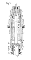
- Fig. 3 shows a modified embodiment in which the valve seat can dodge. But this form can also with a deformable zone on the valve element 6 can be used together. Same and corresponding Parts have the same reference numbers Mistake. In Fig. 3 most of the housing parts are omitted.
- the valve seat 8 is arranged on a valve seat carrier 14.
- the valve seat support is via a spring 15 Supported housing 2.
- the valve seat support On its facing the valve element 6
- the valve seat support has a groove 17 in which a snap ring 16 or another spring ring) is arranged radially somewhat from the groove 17th protrudes so that it under the action of the spring 15 a counter stop 18 can rest in the housing.
- a Sealing ring 19 Between the valve seat support 14 and the housing is a Sealing ring 19 arranged.
- the counter stop 18 forms a limit of a trajectory 20 for the snap ring 16 in the housing 2. This path of movement has an extension in the order of 1 to 3 mm.
- FIG. 3 A situation is shown in the left half of FIG. in which the valve element 6 on the valve seat 8 is applied and the valve seat support 14 is in its rest position located.
- the right half of Fig. 3 represents a situation in which the valve seat support 14 is compressed with the valve element 6 lying around to increase the volume of the valve chamber 13.
- this radiator valve is similar to that of the embodiment of Fig. 1. If the valve element 6 with "wrong" flow direction on the Valve seat 8 lowers, it will when a certain Minimum distance suddenly on the valve seat 8 lowered. The valve seat support 14 is then by Valve element 6 and the pressure acting thereon in the Valve chamber 13 moves further in the direction in which also the valve element 6 has been moved when closing is. This increases the volume of the valve chamber 13, so that there is no water hammer.
- FIG. 4 shows a further embodiment of a radiator valve, which largely corresponds to that of FIG. 1. The same parts are therefore with the same reference numerals Mistake.
- valve element 6 is in the area which later lies on the valve seat 8, with a rubber membrane which later covered a wall 23 on one Compensation area 21 forms.
- the compensation area 21 is shown here as a cavity. But this is not absolutely necessary.
- the wall 23 can also be on the valve element 6 concerns.
- the compensation area 21 is via a channel 22 which passes through the valve element 6, connected to the valve chamber 13.
- valve when the valve is closed, i.e. the valve element 6 with the interposition of the wall 23 on the valve seat 8 is present, then the wall 23 can rise when the pressure rises bend into the valve seat at the outlet connection 4 and thus that associated with the valve chamber 13 Increase volume.
- This increase in volume is only small, but it is sufficient to amount of liquid flowing in a water hammer record and thus the "water hammer" effects defuse.
Landscapes
- Engineering & Computer Science (AREA)
- General Engineering & Computer Science (AREA)
- Mechanical Engineering (AREA)
- Details Of Valves (AREA)
- Safety Valves (AREA)
- Temperature-Responsive Valves (AREA)
- Lift Valve (AREA)
- Taps Or Cocks (AREA)
Abstract
Description
- Fig. 1
- eine erste Ausführungsform eines Heizkörperventils,
- Fig. 2
- eine vergrößerte Darstellung eines Ausschnitts des Heizkörperventils nach Fig. 1,
- Fig.3
- eine zweite Ausführungsform eines Heizkörperventils und
- Fig. 4
- eine dritte Ausführungsform eines Heizkörperventils
Claims (12)
- Ventil, insbesondere Heizkörperventil, mit einem Gehäuse, daß einen Einströmanschluß und einen Ausströmanschluß aufweist, wobei im Strömungspfad zwischen Einströmanschluß und Ausströmanschluß eine Absperreinrichtung angeordnet ist, die einen Ventilsitz und ein damit zusammenwirkendes Ventilelement aufweist, wobei das Ventilelement in einer Ventilkammer bewegbar ist, dadurch gekennzeichnet, daß die Absperreinrichtung (5) eine Anschlagshilfseinrichtung aufweist, die dem am Ventilsitz (8) anliegenden Ventilelement (6) oder einem Teil davon eine Weiterbewegung in Schließrichtung unter Vergrößerung des Volumens der Ventilkammer (13) erlaubt.
- Ventil nach Anspruch 1, dadurch gekennzeichnet, daß die Anschlaghilfseinrichtung durch eine Federanordnung (12, 15) gebildet ist, die dem Ventilelement und/oder dem Ventilsitz (8) zugeordnet ist.
- Ventil nach Anspruch 1 oder 2, dadurch gekennzeichnet, daß am Ventilelement (6) eine deformierbare Zone ausgebildet ist.
- Ventil nach Anspruch 3, dadurch gekennzeichnet, daß die deformierbare Zone (12) dem Ventilsitz (8) benachbart ist.
- Ventil nach Anspruch 4, dadurch gekennzeichnet, daß die deformierbare Zone (12) als Ringwand (11) ausgebildet ist.
- Ventil nach Anspruch 5, dadurch gekennzeichnet, daß die Ringwand (11) aus einem gummieleastischem Material gebildet ist.
- Ventil nach einem der Ansprüche 1 bis 6, dadurch gekennzeichnet, daß das Ventilelement (6) einen mit einem kompressiblen Fluid gefüllten Druckraum aufweist, der von der Ventilkammer durch eine verformbare Membrane getrennt ist.
- Ventil nach einem der Ansprüche 1 bis 7, dadurch gekennzeichnet, daß das Ventilelement (6) auf seiner dem Ventilsitz (8) zugewandte Seite einen von einer verformbaren Wand (23) abgedeckten Ausweichbereich (21) aufweist, der mit der Ventilkammer (13) über einen Kanal (22) im Ventilelement (6) in Verbindung steht.
- Ventil nach einem der Ansprüche 1 bis 8, dadurch gekennzeichnet, daß der Ventilsitz (8) auf einem Ventilsitzträger (14) angeordnet ist, der über ein Feder (15) im Gehäuse (2) abgestützt ist.
- Ventil nach Anspruch 9, dadurch gekennzeichnet, daß der Ventilsitzträger (14) einen Anschlag (16) aufweist, der unter der Wirkung der Feder (15) an einem Gegenanschlag (18) im Gehäuse anliegt.
- Ventil nach Anspruch 10, dadurch gekennzeichnet, daß der Anschlag (16) durch einen Ring gebildet ist, der in einer Nut (17) am Ventilsitzträger (14) angeordnet ist und aus dieser Nut (17) radial vorsteht.
- Ventil nach einem der Ansprüche 9 bis 11, dadurch gekennzeichnet, daß zwischen dem Ventilsitzträger (14) und dem Gehäuse (2) ein Dichtring (19) angeordnet ist.
Applications Claiming Priority (2)
| Application Number | Priority Date | Filing Date | Title |
|---|---|---|---|
| DE10048689 | 2000-09-30 | ||
| DE10048689A DE10048689B4 (de) | 2000-09-30 | 2000-09-30 | Heizkörperventil |
Publications (3)
| Publication Number | Publication Date |
|---|---|
| EP1193430A2 true EP1193430A2 (de) | 2002-04-03 |
| EP1193430A3 EP1193430A3 (de) | 2003-03-19 |
| EP1193430B1 EP1193430B1 (de) | 2007-12-19 |
Family
ID=7658357
Family Applications (1)
| Application Number | Title | Priority Date | Filing Date |
|---|---|---|---|
| EP01203527A Expired - Lifetime EP1193430B1 (de) | 2000-09-30 | 2001-09-18 | Ventil, insbesondere Heizkörperventil |
Country Status (3)
| Country | Link |
|---|---|
| EP (1) | EP1193430B1 (de) |
| AT (1) | ATE381688T1 (de) |
| DE (1) | DE10048689B4 (de) |
Cited By (2)
| Publication number | Priority date | Publication date | Assignee | Title |
|---|---|---|---|---|
| WO2005015066A1 (de) * | 2003-08-07 | 2005-02-17 | Danfoss A/S | Fluidsteuerventil, insbesondere warmwasserventil |
| WO2008035193A1 (en) * | 2006-09-21 | 2008-03-27 | Itw Automotive Products Gmbh & Co. Kg | Thermostat valve |
Citations (1)
| Publication number | Priority date | Publication date | Assignee | Title |
|---|---|---|---|---|
| WO1999022282A1 (en) | 1997-10-23 | 1999-05-06 | Myson Heating Controls Limited | Flow control valves |
Family Cites Families (16)
| Publication number | Priority date | Publication date | Assignee | Title |
|---|---|---|---|---|
| US2397269A (en) * | 1943-10-19 | 1946-03-26 | Adel Prec Products Corp | Composite valve member |
| DE1098311B (de) * | 1956-11-12 | 1961-01-26 | Baltzar Carl Von Platen Dipl I | Wasserhahn |
| DE1086095B (de) * | 1957-02-15 | 1960-07-28 | Gusswerk Paul Saalmann & Soehn | Ventil mit aus Kunststoff bestehendem schraubbarem Absperrkoerper |
| US3027134A (en) * | 1958-01-31 | 1962-03-27 | Rand Dev Corp | Noiseless valve |
| GB930908A (en) * | 1958-11-25 | 1963-07-10 | Anthony John Hardcastle | Closures for stop and control valves |
| DE1288857B (de) * | 1965-08-13 | 1969-02-06 | Herion Erich | Magnetisch schaltbares Sitzventil fuer hohe Druecke mit elastischer Verschlussstueckausbildung |
| US3410524A (en) * | 1966-08-01 | 1968-11-12 | Richard E Self | Control valve |
| FR2240390A1 (en) * | 1973-08-07 | 1975-03-07 | Piel Ets P | Seal for off spindle valve - made from elastic material to allow deformation under dynamic fluid pressure |
| DE2525243A1 (de) * | 1975-06-06 | 1976-12-23 | Heimeier Gmbh Metall Theodor | Heizungsventil |
| DE2614510A1 (de) * | 1976-04-03 | 1977-10-06 | Hansa Metallwerke Ag | Wasserauslaufarmatur mit einem niederschraubventil |
| DE2852882B2 (de) * | 1978-12-07 | 1981-03-12 | Zahnradfabrik Friedrichshafen Ag, 7990 Friedrichshafen | Ventil, insbesondere Druckventil für eine Kolbenpumpe |
| DE3543330C1 (de) * | 1985-12-07 | 1986-10-09 | Honeywell-Braukmann GmbH, 6950 Mosbach | Thermostatventil |
| DE4217006A1 (de) * | 1992-05-22 | 1993-11-25 | Grohe Kg Hans | Absperrventil |
| DE9319620U1 (de) * | 1992-12-18 | 1994-02-10 | Weka AG, Wetzikon | Ventil |
| DE29613267U1 (de) * | 1996-07-31 | 1996-09-19 | Kermi Gmbh, 94447 Plattling | Ventil |
| DE19740580C2 (de) * | 1997-09-16 | 2001-06-13 | Pierburg Ag | Elektromagnetisches Schaltventil |
-
2000
- 2000-09-30 DE DE10048689A patent/DE10048689B4/de not_active Expired - Fee Related
-
2001
- 2001-09-18 EP EP01203527A patent/EP1193430B1/de not_active Expired - Lifetime
- 2001-09-18 AT AT01203527T patent/ATE381688T1/de not_active IP Right Cessation
Patent Citations (1)
| Publication number | Priority date | Publication date | Assignee | Title |
|---|---|---|---|---|
| WO1999022282A1 (en) | 1997-10-23 | 1999-05-06 | Myson Heating Controls Limited | Flow control valves |
Cited By (4)
| Publication number | Priority date | Publication date | Assignee | Title |
|---|---|---|---|---|
| WO2005015066A1 (de) * | 2003-08-07 | 2005-02-17 | Danfoss A/S | Fluidsteuerventil, insbesondere warmwasserventil |
| CN100378380C (zh) * | 2003-08-07 | 2008-04-02 | 丹佛斯公司 | 液体控制阀 |
| WO2008035193A1 (en) * | 2006-09-21 | 2008-03-27 | Itw Automotive Products Gmbh & Co. Kg | Thermostat valve |
| US7971797B2 (en) | 2006-09-21 | 2011-07-05 | Itw Automotive Products Gmbh & Co. Kg | Thermostat valve |
Also Published As
| Publication number | Publication date |
|---|---|
| EP1193430B1 (de) | 2007-12-19 |
| DE10048689B4 (de) | 2006-06-08 |
| DE10048689A1 (de) | 2002-04-25 |
| ATE381688T1 (de) | 2008-01-15 |
| EP1193430A3 (de) | 2003-03-19 |
Similar Documents
| Publication | Publication Date | Title |
|---|---|---|
| DE69832042T2 (de) | Absperrfülventil | |
| DE2932114C2 (de) | Bimetallgesteuerter Kondensatableiter | |
| EP0122323A1 (de) | Doppelsitzventil mit zwei Ventiltellern | |
| EP0067403A1 (de) | Hahn mit Kugelküken | |
| EP1741843B1 (de) | Systemtrenner | |
| DE2419515A1 (de) | Ventilbaugruppe insbesondere zur verwendung in einem kuehlsystem | |
| DE102018205016A1 (de) | Druckminderer | |
| DE10257517B4 (de) | Rückflußverhinderer | |
| EP3736654B1 (de) | Druckminderer | |
| DE2460267C3 (de) | Strömungsmittelsteuerventil | |
| DE10048689B4 (de) | Heizkörperventil | |
| WO2021204453A1 (de) | Ventil und verwendung einer dämpfungsvorrichtung | |
| DE4306866A1 (de) | Selbsttätig schließendes Wasserventil | |
| DE1550453A1 (de) | Geraet zum Mischen unterschiedliche Temperaturen aufweisender Medien | |
| DE19944365B4 (de) | Ventil, insbesondere Heizkörperventil | |
| DE10055614B4 (de) | Ventil,insbesondere Heizkörprventil | |
| DE102005031717B4 (de) | Heizkörperventil | |
| DE102016216045A1 (de) | Stößelventil für Getränkemaschine | |
| WO2004092591A1 (de) | Stetig verstellbares wegeventil | |
| DE10048687B4 (de) | Ventil, insbesondere Heizkörperventil | |
| DE102020109245B4 (de) | Getränkezubereitungsvorrichtung mit Membranventil | |
| EP2313675B1 (de) | Ventilvorrichtung sowie verfahren zum betreiben einer ventilvorrichtung | |
| DE19855755C2 (de) | Zweistufiger Gasdruckregler | |
| AT213184B (de) | Ventil od. dgl. Dichtungselement hiefür | |
| EP3553238B1 (de) | Ablaufvorrichtung für flüssigkeiten mit als geruchsverschluss wirkender rückstausperre |
Legal Events
| Date | Code | Title | Description |
|---|---|---|---|
| PUAI | Public reference made under article 153(3) epc to a published international application that has entered the european phase |
Free format text: ORIGINAL CODE: 0009012 |
|
| AK | Designated contracting states |
Kind code of ref document: A2 Designated state(s): AT BE CH CY DE DK ES FI FR GB GR IE IT LI LU MC NL PT SE TR |
|
| AX | Request for extension of the european patent |
Free format text: AL;LT;LV;MK;RO;SI |
|
| PUAL | Search report despatched |
Free format text: ORIGINAL CODE: 0009013 |
|
| AK | Designated contracting states |
Kind code of ref document: A3 Designated state(s): AT BE CH CY DE DK ES FI FR GB GR IE IT LI LU MC NL PT SE TR |
|
| AX | Request for extension of the european patent |
Extension state: AL LT LV MK RO SI |
|
| 17P | Request for examination filed |
Effective date: 20030408 |
|
| AKX | Designation fees paid |
Designated state(s): AT DE FR GB IT |
|
| 17Q | First examination report despatched |
Effective date: 20041214 |
|
| GRAP | Despatch of communication of intention to grant a patent |
Free format text: ORIGINAL CODE: EPIDOSNIGR1 |
|
| RIN1 | Information on inventor provided before grant (corrected) |
Inventor name: GARM, FESTER Inventor name: MESSMER, JAMES DAVID |
|
| GRAS | Grant fee paid |
Free format text: ORIGINAL CODE: EPIDOSNIGR3 |
|
| GRAA | (expected) grant |
Free format text: ORIGINAL CODE: 0009210 |
|
| RBV | Designated contracting states (corrected) |
Designated state(s): AT FR GB IT |
|
| AK | Designated contracting states |
Kind code of ref document: B1 Designated state(s): AT FR GB IT |
|
| REG | Reference to a national code |
Ref country code: GB Ref legal event code: FG4D Free format text: NOT ENGLISH |
|
| REG | Reference to a national code |
Ref country code: DE Ref legal event code: 8566 |
|
| EN | Fr: translation not filed | ||
| PLBE | No opposition filed within time limit |
Free format text: ORIGINAL CODE: 0009261 |
|
| STAA | Information on the status of an ep patent application or granted ep patent |
Free format text: STATUS: NO OPPOSITION FILED WITHIN TIME LIMIT |
|
| 26N | No opposition filed |
Effective date: 20080922 |
|
| PG25 | Lapsed in a contracting state [announced via postgrant information from national office to epo] |
Ref country code: FR Free format text: LAPSE BECAUSE OF FAILURE TO SUBMIT A TRANSLATION OF THE DESCRIPTION OR TO PAY THE FEE WITHIN THE PRESCRIBED TIME-LIMIT Effective date: 20081010 |
|
| GBPC | Gb: european patent ceased through non-payment of renewal fee |
Effective date: 20080918 |
|
| PG25 | Lapsed in a contracting state [announced via postgrant information from national office to epo] |
Ref country code: AT Free format text: LAPSE BECAUSE OF NON-PAYMENT OF DUE FEES Effective date: 20080918 |
|
| PG25 | Lapsed in a contracting state [announced via postgrant information from national office to epo] |
Ref country code: GB Free format text: LAPSE BECAUSE OF NON-PAYMENT OF DUE FEES Effective date: 20080918 |
|
| PG25 | Lapsed in a contracting state [announced via postgrant information from national office to epo] |
Ref country code: IT Free format text: LAPSE BECAUSE OF NON-PAYMENT OF DUE FEES Effective date: 20080930 |