EP1193173A2 - Control system for a ship drive - Google Patents
Control system for a ship drive Download PDFInfo
- Publication number
- EP1193173A2 EP1193173A2 EP20010122809 EP01122809A EP1193173A2 EP 1193173 A2 EP1193173 A2 EP 1193173A2 EP 20010122809 EP20010122809 EP 20010122809 EP 01122809 A EP01122809 A EP 01122809A EP 1193173 A2 EP1193173 A2 EP 1193173A2
- Authority
- EP
- European Patent Office
- Prior art keywords
- ship
- value
- speed
- setpoint
- control system
- Prior art date
- Legal status (The legal status is an assumption and is not a legal conclusion. Google has not performed a legal analysis and makes no representation as to the accuracy of the status listed.)
- Withdrawn
Links
Images

Classifications
-
- B—PERFORMING OPERATIONS; TRANSPORTING
- B63—SHIPS OR OTHER WATERBORNE VESSELS; RELATED EQUIPMENT
- B63H—MARINE PROPULSION OR STEERING
- B63H3/00—Propeller-blade pitch changing
- B63H3/10—Propeller-blade pitch changing characterised by having pitch control conjoint with propulsion plant control
-
- B—PERFORMING OPERATIONS; TRANSPORTING
- B63—SHIPS OR OTHER WATERBORNE VESSELS; RELATED EQUIPMENT
- B63H—MARINE PROPULSION OR STEERING
- B63H21/00—Use of propulsion power plant or units on vessels
- B63H21/22—Use of propulsion power plant or units on vessels the propulsion power units being controlled from exterior of engine room, e.g. from navigation bridge; Arrangements of order telegraphs
-
- F—MECHANICAL ENGINEERING; LIGHTING; HEATING; WEAPONS; BLASTING
- F02—COMBUSTION ENGINES; HOT-GAS OR COMBUSTION-PRODUCT ENGINE PLANTS
- F02D—CONTROLLING COMBUSTION ENGINES
- F02D29/00—Controlling engines, such controlling being peculiar to the devices driven thereby, the devices being other than parts or accessories essential to engine operation, e.g. controlling of engines by signals external thereto
- F02D29/02—Controlling engines, such controlling being peculiar to the devices driven thereby, the devices being other than parts or accessories essential to engine operation, e.g. controlling of engines by signals external thereto peculiar to engines driving vehicles; peculiar to engines driving variable pitch propellers
Definitions
- the invention relates to a control system for a ship propulsion system with a driving lever, whose position represents a desired performance, with a setpoint specification for Specification of a setpoint depending on the position of the drive lever and with a Speed control loop for speed control of a motor based on the setpoint.
- Such a control system is known for example from DE 198 12 514 C2. From the DE 195 15 481 C2 in turn is a control system for a ship propulsion system Variable pitch propeller known. With this control system, the setpoint specification is calculated in Depending on the position of the drive lever, a setpoint for the speed control loop and a setpoint for the control loop of the variable pitch propeller.
- the invention is based on the object of operating a ship propulsion system simplify.
- Vessel speed control loop for vessel speed control is activated.
- the ship's speed control loop acts on the speed control loop.
- the The ship's speed control loop in turn is largely determined by the position of the Drive lever determined. In other words: in the first mode of operation is dependent the position of the drive lever set a corresponding speed of the engine.
- the second operating mode is also the ship's speed via the control lever specified.
- the solution according to the invention and its configurations offer the advantage that exclusively via a control element, i.e. the drive lever, the ship's drive can be adjusted accordingly.
- a control element i.e. the drive lever
- the result is a significantly simplified one Service.
- the setpoint specification is used the setpoint for all motors and variable pitch propellers is specified.
- the available drive power of the motors is also taken into account here. This has the advantage that the motors are utilized evenly.
- FIG 1 is a greatly simplified block diagram of a propulsion system for a ship shown.
- the propeller 7 is designed as an adjustable propeller. Accordingly is a speed control loop, consisting of the engine speed controller 3 and engine 4, and a variable-pitch propeller control loop, consisting of variable-pitch propeller controller 5 and Propeller adjustment device 6, shown.
- the invention is also at a drive system with a fixed propeller applicable. In this case the Variable-pitch propeller control loop is eliminated.
- a driving lever 1 is shown. As is known, the ship's captain gives the direction of travel and via this control lever 1 the position FS the performance request.
- the drive lever 1 has a Selection device for selecting the operating mode, signal MOD, on.
- the setpoint specification 2 is given as further input signal the actual ship speed vIST. In practice, this is Actual ship speed vIST provided by a ship log or the GPS.
- the setpoint specification 2 has a setpoint nSW as output variables, correspondingly a speed value, and a target value PhiSW, corresponding to a slope for the Propeller.
- the setpoint nSW is therefore the reference variable for the speed control loop.
- the speed control of the motor 4 is carried out in a known manner a control deviation is determined from the setpoint nSW and the actual speed value nIST. From this control deviation, the engine speed controller 3 determines which manipulated variable the motor 4 is supplied.
- the speed of the motor 4 then corresponds to the actual speed value nIST.
- the pitch angle setpoint of the variable pitch propeller becomes PhiSW and the actual pitch angle value PhiIST determined a control deviation.
- Out the control propeller controller 5 calculates a control variable for this control deviation Propeller adjustment device 6.
- the output variable of the propeller adjustment device 6 in turn corresponds to the pitch angle actual value PhiIST of the variable pitch propeller.
- the setpoint specification 2 specifies the setpoint nSW (i) and PhiSW (j) for all motors, the run variable i corresponding to the number of motors 4 and j to the number of propellers 7 equivalent.
- the drive power is also taken into account. If, for example, the currently available propulsion power is not sufficient to achieve the desired ship speed, the reduction in the setpoint PhiSW (j) reduces the pitch of the propeller and at the same time increases the engine speed by increasing the setpoint nSW (i).
- An electric motor or a gas turbine can of course also be used as the ship's drive as the motor 4. Instead of a fixed or adjustable propeller, a waterjet can also be used.
- a block diagram of the setpoint specification 2 is shown in FIG.
- the input variables are: The position FS of the control lever 1, the actual ship speed vIST and that Signal MOD, the value of which is the first operating mode MOD1 or second operating mode MOD2 indicates.
- the output variables of setpoint specification 2 are: The setpoint nSW and the setpoint PhiSW.
- a drive system with several motors and several Propellers 7 sets the setpoint 2 a corresponding number of setpoints nSW (i) or PhiSW (j) ready, where the running variable i corresponds to the number of motors 4 and j corresponds to the number of propellers 7.
- this embodiment is by two Arrows labeled.
- a display 12 is a further output variable of the setpoint specification 2 shown.
- the ship's speed setpoint vSW becomes permanent for the skipper represents, d. H. regardless of the selected operating mode.
- the display 12 can Driving lever 1 can be integrated.
- the ship's captain can already use this display 12 Activation of the second operating mode MOD2 the desired ship speed to adjust.
- the setpoint specification 2 has the following function blocks: characteristic curve 8, PI element 9, comparator 10 and map 11. Via the characteristic 8, the position FS of the Travel lever 1 calculates the ship's speed setpoint vSW.
- the display 12 will the ship's speed setpoint vSW is shown to the skipper, which with the current drive configuration (motor connected and coupled) can be reached.
- the first drive lever value FS1 and the position FS of the drive lever 1 and the signal of the operating mode, corresponding to MOD1 or MOD2, represent the Input variables of the comparator 10.
- the comparator 10 determines depending on the Operating mode a second drive lever value FS2 as an output variable. This is on that Map 11 performed.
- the second drive lever value FS2 becomes the characteristic diagram 11 Setpoints nSW and PhiSW or nSW (i) and PhiSW (j) are calculated.
- the comparator 10 sets the second driving lever value FS2 to the value corresponding to the position FS of the driving lever 1.
- the setpoints nSW and PhiSW are thus directly coupled to the position FS of the driving lever 1, ie Speed control loop is active.
- the second drive lever value FS2 is calculated as a function of the position FS of the drive lever 1 and the first drive lever value FS1.
- the ship's speed control loop is thus active in addition to the speed control loop.
- the setpoint specification 2 calculates the setpoint for the speed control loop nSW and the setpoint PhiSW for the variable-pitch propeller control loop depending on the available drive power. If, for example, the currently available propulsion power is not sufficient to achieve the desired ship speed, the slope of the propeller is reduced by reducing the setpoint PhiSW and, at the same time, the engine speed is increased by increasing the setpoint nSW.
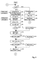
- FIG. 1 A program flow chart is shown in FIG. After initializing a electronic control unit, the operating mode MOD is queried in step S1. Will the first operating mode MOD 1 is detected, the program flow is carried out with steps S2 to Go through S4. If the second operating mode MOD2 is determined, the Run through the program sequence with steps S5 to S19.
- step S2 the speed control is activated in step S2.
- step S3 the second drive lever value FS2 becomes the value set according to the position FS of the drive lever 1.
- step S4 in The setpoint nSW or PhiSW is calculated as a function of the second drive lever value FS2. The program flow then branches to point A and continues with step S 1.
- step S5 in addition to the speed control, the ship speed control activated after checking for admissibility.
- the activation of the ship's speed control is permissible if the actual ship speed vIST is a plausible one Has value. If the actual ship speed vIST is not plausible, for example, because there is no value due to a fault, the first one Operating mode MOD1 activated.
- it can be checked whether the drive lever 1 is located in the driving area. For example, when maneuvering in the port is one Vessel speed control does not make sense.
- Driving lever position FS read.
- step S7 the position FS of the driving lever becomes 1 a ship speed target value vSW is calculated using characteristic curve 8.
- step S8 the Actual ship speed vIST read in.
- the actual ship speed can are provided by a ship log or GPS.
- step S9 is off a ship speed deviation from the target and actual value of the ship speed dv calculated.
- step S10 it is checked whether the ship speed deviation dv is greater than a limit value GW. If the test result is positive, step S11 also issued an error message to the skipper and the program continued at step S12.
- the error message can be, for example, an acoustic or visual alarm.
- Step S12 a first drive lever value FS1 from the ship speed deviation dv certainly. It is then checked in step S13 whether the first drive lever value FS1 is within a tolerance band, correspondingly represented by the limit values GW1 and GW2, lies. If this is not the case, the first drive lever value FS1 becomes one in step S14 fixed value is limited and the program continues at step S15. At step S13 found that the first drive lever value FS1 lies within the tolerance band, then at step S15 depending on the position FS of the drive lever 1 and the first Driving lever value FS 1 calculates a second driving lever value FS2.
- step F16 checked whether this second drive lever value FS2 is within a tolerance band, accordingly represented by the two limit values GW1 and GW2. Is not this if this is the case, this second driving lever value is limited to a fixed value in step S17. If the test result in step S16 is positive, then step S18 depends on the second driving lever value FS2 the setpoint nSW or PhiSW by means of the map 11 calculated. The program flow then branches to point A and the program starts again at step S1.
Abstract
Description
Die Erfindung betrifft ein Regelsystem für einen Schiffsantrieb mit einem Fahrhebel, dessen Stellung einen Leistungswunsch repräsentiert, mit einer Sollwert-Vorgabe zur Vorgabe eines Sollwerts in Abhängigkeit der Stellung des Fahrhebels und mit einem Drehzahl-Regelkreis zur Drehzahl-Regelung eines Motors anhand des Sollwerts.The invention relates to a control system for a ship propulsion system with a driving lever, whose position represents a desired performance, with a setpoint specification for Specification of a setpoint depending on the position of the drive lever and with a Speed control loop for speed control of a motor based on the setpoint.
Ein derartiges Regelsystem ist beispielsweise aus der DE 198 12 514 C2 bekannt. Aus der DE 195 15 481 C2 wiederum ist ein Regelsystem für einen Schiffsantrieb mit Verstellpropeller bekannt. Bei diesem Regelsystem berechnet die Sollwert-Vorgabe in Abhängigkeit der Stellung des Fahrhebels einen Sollwert für den Drehzahl-Regelkreis und einen Sollwert für den Regelkreis des Verstellpropellers.Such a control system is known for example from DE 198 12 514 C2. From the DE 195 15 481 C2 in turn is a control system for a ship propulsion system Variable pitch propeller known. With this control system, the setpoint specification is calculated in Depending on the position of the drive lever, a setpoint for the speed control loop and a setpoint for the control loop of the variable pitch propeller.
Beiden Regelsystemen ist gemeinsam, dass sich in Abhängigkeit der Stellung des Fahrhebels eine entsprechende Drehzahl am Schiffsantrieb bzw. Schiffsgeschwindigkeit einstellt. Die resultierende Schiffsgeschwindigkeit kann sich jedoch auf Grund von äußeren Einflüssen, beispielsweise Wellengang und Wind, ändern. Hieraus entsteht in der Praxis nun das Problem, dass eine konstant gewünschte Schiffsgeschwindigkeit nur dadurch zu erreichen ist, indem der Schiffsführer über manuelle Korrektur des Fahrhebels die Störgrößen ausgleicht.Both control systems have in common that depending on the position of the Driving lever a corresponding speed at the ship's propulsion or ship's speed established. The resulting ship speed may vary due to external factors Influences such as waves and wind change. This results in practice now the problem that a constant desired ship speed only because of this is achieved by the skipper via manual correction of the driving lever Compensates for disturbances.
Der Erfindung liegt insofern die Aufgabe zu Grunde, die Bedienung eines Schiffsantriebs zu vereinfachen.In this respect, the invention is based on the object of operating a ship propulsion system simplify.
Die Aufgabe wird erfindungsgemäß durch die Merkmale des Anspruchs 1 gelöst. In den
Unteransprüchen sind vorteilhafte Ausgestaltungen hierzu dargestellt.The object is achieved by the features of
Erfindungsgemäß wird somit vorgeschlagen, dass neben der Drehzahl-Regelung des Motors, entsprechend einer ersten Betriebsart, in einer zweiten Betriebsart zusätzlich ein Schiffsgeschwindigkeits-Regelkreis zur Schiffsgeschwindigkeits-Regelung aktiviert wird. Der Schiffsgeschwindigkeits-Regelkreis wirkt auf den Drehzahl-Regelkreis ein. Der Schiffgeschwindigkeits-Regelkreis wiederum wird maßgeblich von der Stellung des Fahrhebels bestimmt. Mit anderen Worten: In der ersten Betriebsart wird in Abhängigkeit der Stellung des Fahrhebels eine entsprechende Drehzahl des Motors eingestellt. In der zweiten Betriebsart wird ebenfalls über den Fahrhebel die Schiffsgeschwindigkeit vorgegeben.According to the invention it is thus proposed that in addition to the speed control of the Motors, corresponding to a first operating mode, additionally in a second operating mode Vessel speed control loop for vessel speed control is activated. The ship's speed control loop acts on the speed control loop. The The ship's speed control loop in turn is largely determined by the position of the Drive lever determined. In other words: in the first mode of operation is dependent the position of the drive lever set a corresponding speed of the engine. In the The second operating mode is also the ship's speed via the control lever specified.
Die erfindungsgemäße Lösung und deren Ausgestaltungen bieten den Vorteil, dass ausschließlich über ein Bedienelement, also der Fahrhebel, der Schiffsantrieb entsprechend eingestellt werden kann. Über die Regelung der Schiffsgeschwindigkeit werden die äußeren Einflüsse mitberücksichtigt, so dass ein manuelles Nachführen des Fahrhebels entfällt. In Konsequenz ergibt sich somit eine wesentlich vereinfachte Bedienung. Bei einem Schiffsantrieb mit mehreren Motoren wird über die Sollwert-Vorgabe der Sollwert für alle Motoren sowie Verstellpropeller vorgegeben. Bei der Berechnung des Sollwerts wird hierbei die verfügbare Antriebsleistung der Motoren mitberücksichtigt. Hierdurch ergibt sich der Vorteil, dass die Motoren gleichmäßig ausgelastet werden.The solution according to the invention and its configurations offer the advantage that exclusively via a control element, i.e. the drive lever, the ship's drive can be adjusted accordingly. About regulation of ship speed the external influences are taken into account, so that a manual tracking of the Driving lever is omitted. As a consequence, the result is a significantly simplified one Service. In the case of a ship propulsion system with several motors, the setpoint specification is used the setpoint for all motors and variable pitch propellers is specified. When calculating the The available drive power of the motors is also taken into account here. This has the advantage that the motors are utilized evenly.
In den Zeichnungen ist ein bevorzugtes Ausführungsbeispiel dargestellt. Es zeigen:
Figur 1- ein Blockschaltbild;
Figur 2- Blockschaltbild der Sollwert-Vorgabe;
Figur 3- ein Programmablaufplan
- Figure 1
- a block diagram;
- Figure 2
- Block diagram of the setpoint specification;
- Figure 3
- a program schedule
In Figur 1 ist ein stark vereinfachtes Blockschaltbild einer Antriebsanlage für ein Schiff
dargestellt. Der Propeller 7 ist hierbei als Verstellpropeller ausgeführt. Dementsprechend
ist ein Drehzahl-Regelkreis, bestehend aus dem Motordrehzahl-Regler 3 und Motor 4, und
ein Verstellpropeller-Regelkreis, bestehend aus dem Verstellpropeller-Regler 5 und
Propeller-Verstelleinrichtung 6, dargestellt. Selbstverständlich ist die Erfindung auch bei
einer Antriebsanlage mit einem Festpropeller anwendbar. In diesem Fall würde der
Verstellpropeller-Regelkreis entfallen. In Figur 1 ist ein Fahrhebel 1 dargestellt.
Bekanntermaßen gibt der Schiffsführer über diesen Fahrhebel 1 die Fahrrichtung und über
die Stellung FS den Leistungswunsch vor. Zusätzlich weist der Fahrhebel 1 eine
Auswahleinrichtung zur Auswahl der Betriebsart, Signal MOD, auf. Beide Signale FS und
MOD werden auf eine Sollwert-Vorgabe 2 geführt. Die Sollwert-Vorgabe 2 erhält als
weiteres Eingangssignal den Schiffsgeschwindigkeits-lstwert vIST. In der Praxis wird dieser
Schiffsgeschwindigkeits-lstwert vIST von einem Schiffs-Log oder dem GPS bereitgestellt.
Die Sollwert-Vorgabe 2 besitzt als Ausgangsgrößen einen Sollwert nSW, entsprechend
einem Drehzahlwert, und einen Sollwert PhiSW, entsprechend einer Steigung für den
Verstellpropeller. Der Sollwert nSW ist somit die Führungsgröße für den Drehzahl-Regelkreis.
Die Drehzahl-Regelung des Motors 4 erfolgt in bekannter Weise indem aus
dem Sollwert nSW und dem Drehzahl-Istwert nIST eine Regelabweichung bestimmt wird.
Aus dieser Regelabweichung bestimmt der Motordrehzahl-Regler 3 eine Stellgröße, welche
dem Motor 4 zugeführt wird. Die Drehzahl des Motors 4 entspricht sodann dem Drehzahllstwert
nIST. Parallel hierzu wird aus dem Steigungswinkel-Sollwert des Verstellpropellers
PhiSW und dem Steigungswinkel-Istwert PhiIST eine Regelabweichung bestimmt. Aus
dieser Regelabweichung berechnet der Vorstellpropeller-Regler 5 eine Stellgröße für die
Propeller-Verstelleinrichtung 6. Die Ausgangsgröße der Propeller-Verstelleinrichtung 6
wiederum entspricht dem Steigungswinkel-Istwert PhiIST des Verstellpropellers.In Figure 1 is a greatly simplified block diagram of a propulsion system for a ship
shown. The propeller 7 is designed as an adjustable propeller. Accordingly
is a speed control loop, consisting of the
Erfindungsgemäß ist vorgesehen, dass bei einer Antriebsanlage mit mehreren Motoren 4
die Sollwert-Vorgabe 2 den Sollwert nSW(i) und PhiSW(j) für alle Motoren vorgibt, wobei
die Laufvariable i der Anzahl der Motoren 4 entspricht und j der Anzahl der Propeller 7
entspricht. Bei der Berechnung des Sollwerts wird hierbei die Antriebsleistung
mitberücksichtigt. Wenn beispielsweise die momentan verfügbare Antriebsleistung nicht
ausreicht, um die gewünschte Schiffsgeschwindigkeit zu erreichen, wird über die
Verringerung des Sollwerts PhiSW(j) die Steigung des Propellers reduziert, und gleichzeitig
über die Erhöhung des Sollwerts nSW(i) die Motordrehzahlen erhöht.
Als Motor 4 kann selbstverständlich auch ein Elektromotor oder eine Gasturbine als
Schiffsantrieb verwendet werden. Statt eines Fest- oder Verstellpropellers kann auch ein
Waterjet verwendet werden.According to the invention, in a drive system with a plurality of
An electric motor or a gas turbine can of course also be used as the ship's drive as the
In Figur 2 ist ein Blockschaltbild der Sollwert-Vorgabe 2 dargestellt. Die Eingangsgrößen
sind: Die Stellung FS des Fahrhebels 1, der Schiffsgeschwindigkeits-lstwert vIST und das
Signal MOD, dessen Wert den ersten Betriebsmodus MOD1 bzw. zweiten Betriebmodus
MOD2 kennzeichnet. Die Ausgangsgrößen der Sollwert-Vorgabe 2 sind: Der Sollwert nSW
und der Sollwert PhiSW. Bei einer Antriebsanlage mit mehreren Motoren und mehreren
Propellern 7 stellt die Sollwert-Vorgabe 2 eine entsprechende Anzahl an Sollwerten nSW(i)
bzw. PhiSW(j) bereit, wobei die Laufvariable i der Anzahl der Motoren 4 entspricht und j
der Anzahl der Propeller 7 entspricht. In Figur 2 ist diese Ausführungsform durch zwei
Pfeile bezeichnet. Als weitere Ausgangsgröße der Sollwert-Vorgabe 2 ist eine Anzeige 12
dargestellt. Dem Schiffsführer wird der Schiffsgeschwindigkeits-Sollwert vSW permanent
darstellt, d. h. unabhängig vom ausgewählten Betriebsmodus. Die Anzeige 12 kann im
Fahrhebel 1 integriert sein. Mittels dieser Anzeige 12 kann der Schiffsführer bereits vor
Aktivierung des zweiten Betriebsmodus MOD2 die gewünschte Schiffsgeschwindigkeit
einstellen. Die Sollwert-Vorgabe 2 weist folgende Funktionsblöcke auf: Kennlinie 8, Pl-Glied
9, Vergleicher 10 und Kennfeld 11. Über die Kennlinie 8 wird aus der Stellung FS des
Fahrhebels 1 der Schiffsgeschwindigkeits-Sollwert vSW berechnet. Bei der Berechnung
des Schiffsgeschwindigkeits-Sollwert vSW wird die Anzahl der sich im Betrieb und im
eingekuppelten Zustand befindenden Motoren mitberücksichtigt. In der Anzeige 12 wird
dem Schiffsführer derjenige Schiffsgeschwindigkeits-Sollwert vSW dargestellt, welcher mit
der aktuellen Antriebs-Konfiguration (Motor an und eingekuppelt) erreichbar ist. Aus dem
Schiffsgeschwindigkeits-Sollwert vSW und dem Schiffsgeschwindigkeits-Istwert vIST wird
eine Schiffsgeschwindigkeits-Abweichung dv bestimmt. Aus dieser
Schiffsgeschwindigkeits-Abweichung dv wird mittels des PI-Glieds 9 ein erster Fahrhebel-Wert
FS1 bestimmt. Der erste Fahrhebel-Wert FS1 sowie die Stellung FS des Fahrhebels 1
und das Signal der Betriebsart, entsprechend MOD1 oder MOD2, stellen die
Eingangsgrößen des Vergleichers 10 dar. Der Vergleicher 10 bestimmt in Abhängigkeit der
Betriebsart einen zweiten Fahrhebel-Wert FS2 als Ausgangsgröße. Dieser ist auf das
Kennfeld 11 geführt. Über das Kennfeld 11 wird aus dem zweiten Fahrhebel-Wert FS2 die
Sollwerte nSW und PhiSW bzw. nSW(i) und PhiSW(j) berechnet.A block diagram of the
In der ersten Betriebsart MOD1 setzt der Vergleicher 10 den zweiten Fahrhebel-Wert FS2
auf den Wert entsprechend der Stellung FS des Fahrhebels 1. In der ersten Betriebsart
MOD1 sind somit die Sollwerte nSW und PhiSW unmittelbar an die Stellung FS des
Fahrhebels 1 gekoppelt, d. h. der Drehzahl-Regelkreis ist aktiv. In der zweiten Betriebsart
MOD2 wird der zweite Fahrhebel-Wert FS2 in Abhängigkeit der Stellung FS des Fahrhebels
1 und dem ersten Fahrhebel-Wert FS1 berechnet. In der zweiten Betriebsart MOD2 ist
somit zusätzlich zum Drehzahl-Regelkreis der Schiffsgeschwindigkeits-Regelkreis aktiv.
Bei einer Antriebsanlage mit Verstellpropeller berechnet die Sollwert-Vorgabe 2 den
Sollwert für den Drehzahlregelkreis nSW und den Sollwert PhiSW für den Verstellpropeller-Regelkreis
in Abhängigkeit der verfügbaren Antriebsleistung. Wenn beispielsweise die
momentan verfügbare Antriebsleistung nicht ausreicht, um die gewünschte
Schiffsgeschwindigkeit zu erreichen, wird über die Verringerung des Sollwerts PhiSW die
Steigung des Propellers reduziert, und gleichzeitig über die Erhöhung des Sollwerts nSW
die Motordrehzahlen erhöht.In the first operating mode MOD1, the
In the case of a drive system with a variable-pitch propeller, the
In Figur 3 ist ein Programmablaufplan dargestellt. Nach der Initialisierung eines
elektronischen Steuergeräts wird bei Schritt S1 die Betriebsart MOD abgefragt. Wird die
erste Betriebsart MOD 1 detektiert, so wird der Programmablauf mit den Schritten S2 bis
S4 durchlaufen. Wird die zweite Betriebsart MOD2 festgestellt, so wird der
Programmablauf mit den Schritten S5 bis S19 durchlaufen.A program flow chart is shown in FIG. After initializing a
electronic control unit, the operating mode MOD is queried in step S1. Will the
first
In der ersten Betriebsart MOD1 wird bei Schritt S2 die Drehzahl-Regelung aktiviert. Bei
einer Antriebsanlage mit einem Verstellpropeller wird zusätzlich die Steigungswinkel-Regelung
Phi aktiviert. Im·Schritt S3 wird der zweite Fahrhebelwert FS2 auf den Wert
entsprechend der Stellung FS des Fahrhebels 1 gesetzt. Bei Schritt S4 wird in
Abhängigkeit des zweiten Fahrhebel-Werts FS2 der Sollwert nSW bzw. PhiSW berechnet.
Danach verzweigt der Programmablauf zum Punkt A und fährt mit dem Schritt S 1 fort.In the first operating mode MOD1, the speed control is activated in step S2. at
In a drive system with an adjustable propeller, the pitch angle control is also used
Phi activated. In step S3, the second drive lever value FS2 becomes the value
set according to the position FS of the
In der zweiten Betriebsart MOD2, entsprechend der Schiffsgeschwindigkeits-Regelung,
wird bei Schritt S5 neben der Drehzahl-Regelung die Schiffsgeschwindigkeits-Regelung
nach Prüfung auf Zulässigkeit aktiviert. Die Aktivierung der Schiffsgeschwindigkeits-Regelung
ist dann zulässig, wenn der Schiffsgeschwindigkeits-lstwert vIST einen plausiblen
Wert aufweist. Bei einem nicht plausiblen Schiffsgeschwindigkeits-Istwert vIST,
beispielsweise weil auf Grund einer Störung kein Wert vorliegt, wird der erste
Betriebsmodus MOD1 aktiviert. Ergänzend kann geprüft werden, ob der Fahrhebel 1 sich
im Vorausfahrbereich befindet. Beispielsweise beim Manövrieren im Hafen, ist eine
Schiffsgeschwindigkeits-Regelung nicht sinnvoll. Bei Schritt S6 wird sodann die
Fahrhebelstellung FS eingelesen. Bei Schritt S7 wird aus der Stellung FS des Fahrhebels 1
ein Schiffsgeschwindigkeits-Sollwert vSW mittels der Kennlinie 8 berechnet. Parallel wird
hierzu eine Prüfung auf Zulässigkeit durchgeführt. Bei der Berechnung des
Schiffsgeschwindigkeits-Sollwert vSW wird die Anzahl der sich im Betrieb und im
eingekuppelten Zustand befindenden Motoren mitberücksichtigt. Bei Schritt S8 wird der
Schiffsgeschwindigkeits-lstwert vIST eingelesen. Der Schiffsgeschwindigkeits-Istwert kann
hierbei von einem Schiffs-Log oder vom GPS bereitgestellt werden. Bei Schritt S9 wird aus
dem Soll- und Istwert der Schiffsgeschwindigkeit eine Schiffsgeschwindigkeits-Abweichung
dv berechnet. Bei Schritt S10 wird geprüft, ob die Schiffsgeschwindigkeits-Abweichung
dv größer einem Grenzwert GW ist. Bei positivem Prüfergebnis wird bei Schritt
S11 zusätzlich eine Fehlermeldung an den Schiffsführer ausgegeben und das Programm
bei Schritt S12 fortgesetzt. Die Fehlermeldung kann beispielsweise als akustischer oder
visueller Alarm ausgeführt sein. Bei negativem Prüfergebnis im Schritt S10, wird bei
Schritt S12 aus der Schiffsgeschwindigkeits-Abweichung dv ein erster Fahrhebel-Wert FS1
bestimmt. Danach wird bei Schritt S13 geprüft, ob der erste Fahrhebel-Wert FS1 innerhalb
eines Toleranzbandes, entsprechend dargestellt durch die Grenzwerte GW1 und GW2,
liegt. Ist dies nicht der Fall, so wird bei Schritt S14 der erste Fahrhebel-Wert FS1 auf einen
festen Wert limitiert und das Programm bei Schritt S 15 fortgesetzt. Wird bei Schritt S13
festgestellt, dass der erste Fahrhebel-Wert FS1 innerhalb des Toleranzbandes liegt, so wird
bei Schritt S15 in Abhängigkeit der Stellung FS des Fahrhebels 1 und des ersten
Fahrhebel-Werts FS 1 ein zweiter Fahrhebel-Wert FS2 berechnet. Danach wird bei Schritt
F16 geprüft, ob dieser zweite Fahrhebel-Wert FS2 innerhalb eines Toleranzbandes,
entsprechend dargestellt durch die beiden Grenzwerte GW1 und GW2, liegt. Ist dies nicht
der Fall, so wird bei Schritt S17 dieser zweite Fahrhebel-Wert auf einen Festwert begrenzt.
Bei positivem Prüfergebnis im Schritt S16 wird dann bei Schritt S18 in Abhängigkeit des
zweiten Fahrhebel-Werts FS2 der Sollwert nSW bzw. PhiSW mittels des Kennfelds 11
berechnet. Danach verzweigt der Programmablauf zum Punkt A und das Programm
beginnt wieder bei Schritt S1. In the second operating mode MOD2, according to the ship's speed control,
in step S5, in addition to the speed control, the ship speed control
activated after checking for admissibility. The activation of the ship's speed control
is permissible if the actual ship speed vIST is a plausible one
Has value. If the actual ship speed vIST is not plausible,
for example, because there is no value due to a fault, the first one
Operating mode MOD1 activated. In addition, it can be checked whether the
- 11
- Fahrhebellever
- 22
- Sollwert-VorgabeSetpoint input
- 33
- Motordrehzahl-ReglerA motor speed controller
- 44
- Motorengine
- 55
- Verstellpropeller-ReglerThe variable pitch propeller regulator
- 66
- Propeller-VerstelleinrichtungPropeller-adjusting
- 77
- Propellerpropeller
- 88th
- Kennliniecurve
- 99
- PI-GliedPI element
- 1010
- Vergleichercomparator
- 1111
- Kennfeldmap
- 1212
- Anzeigedisplay
Claims (17)
Applications Claiming Priority (2)
| Application Number | Priority Date | Filing Date | Title |
|---|---|---|---|
| DE10048103 | 2000-09-28 | ||
| DE2000148103 DE10048103C2 (en) | 2000-09-28 | 2000-09-28 | Control system for a ship propulsion |
Publications (1)
| Publication Number | Publication Date |
|---|---|
| EP1193173A2 true EP1193173A2 (en) | 2002-04-03 |
Family
ID=7657981
Family Applications (1)
| Application Number | Title | Priority Date | Filing Date |
|---|---|---|---|
| EP20010122809 Withdrawn EP1193173A2 (en) | 2000-09-28 | 2001-09-22 | Control system for a ship drive |
Country Status (2)
| Country | Link |
|---|---|
| EP (1) | EP1193173A2 (en) |
| DE (1) | DE10048103C2 (en) |
Cited By (1)
| Publication number | Priority date | Publication date | Assignee | Title |
|---|---|---|---|---|
| WO2010123636A3 (en) * | 2009-04-24 | 2011-07-21 | General Electric Company | Method and system for controlling propulsion systems |
Families Citing this family (4)
| Publication number | Priority date | Publication date | Assignee | Title |
|---|---|---|---|---|
| DE102006045685B4 (en) * | 2006-09-27 | 2008-07-31 | Mtu Friedrichshafen Gmbh | Method for controlling a marine propulsion system with a surface propeller |
| AU2008257541C1 (en) | 2007-06-01 | 2014-08-28 | Siemens Aktiengesellschaft | Method and apparatus for operation of a marine vessel hybrid propulsion system |
| DE102007031056B4 (en) * | 2007-07-04 | 2009-04-02 | Mtu Friedrichshafen Gmbh | Method for controlling marine propulsion systems with surface propellers |
| DE102019131277B4 (en) * | 2019-11-20 | 2022-03-17 | Man Energy Solutions Se | Method of operating a marine propulsion system |
Citations (2)
| Publication number | Priority date | Publication date | Assignee | Title |
|---|---|---|---|---|
| DE19515481C2 (en) | 1995-04-27 | 1999-09-23 | Mtu Friedrichshafen Gmbh | Procedure for load regulation of a drive system |
| DE19812514C2 (en) | 1998-03-21 | 2000-01-13 | Mtu Friedrichshafen Gmbh | Control device and method for speed control for a ship's drive |
Family Cites Families (2)
| Publication number | Priority date | Publication date | Assignee | Title |
|---|---|---|---|---|
| DE4112192A1 (en) * | 1990-04-14 | 1991-10-17 | Zahnradfabrik Friedrichshafen | Control system for operating ship drive - controls revs of each engine or slip of clutch for coupling drive to propeller shaft |
| DE4125432A1 (en) * | 1991-08-01 | 1993-02-04 | Zahnradfabrik Friedrichshafen | CONTROL SYSTEM FOR OPERATING A DRIVE SYSTEM FOR A SHIP |
-
2000
- 2000-09-28 DE DE2000148103 patent/DE10048103C2/en not_active Expired - Fee Related
-
2001
- 2001-09-22 EP EP20010122809 patent/EP1193173A2/en not_active Withdrawn
Patent Citations (2)
| Publication number | Priority date | Publication date | Assignee | Title |
|---|---|---|---|---|
| DE19515481C2 (en) | 1995-04-27 | 1999-09-23 | Mtu Friedrichshafen Gmbh | Procedure for load regulation of a drive system |
| DE19812514C2 (en) | 1998-03-21 | 2000-01-13 | Mtu Friedrichshafen Gmbh | Control device and method for speed control for a ship's drive |
Cited By (1)
| Publication number | Priority date | Publication date | Assignee | Title |
|---|---|---|---|---|
| WO2010123636A3 (en) * | 2009-04-24 | 2011-07-21 | General Electric Company | Method and system for controlling propulsion systems |
Also Published As
| Publication number | Publication date |
|---|---|
| DE10048103A1 (en) | 2002-04-18 |
| DE10048103C2 (en) | 2002-09-05 |
Similar Documents
| Publication | Publication Date | Title |
|---|---|---|
| DE2746080C2 (en) | ||
| DE2530494C2 (en) | Electronic fuel control device for a gas turbine engine | |
| DE169693T1 (en) | AUTOMATIC CRUISE CONTROL SYSTEM. | |
| DE102007022348A1 (en) | Device and method for fault monitoring | |
| EP1193173A2 (en) | Control system for a ship drive | |
| DE3618844A1 (en) | Method for limiting the speed of an internal combustion engine | |
| DE2724990A1 (en) | DEVICE FOR DETERMINING A DEFECTIVE FUNCTION OF A CONTROL SYSTEM | |
| DE3713522C2 (en) | ||
| DE4412413C1 (en) | Device for optimisation of the rotation speed control behaviour of a miniature electric motor for dentistry purposes | |
| EP1005147B1 (en) | Method and electronic circuit for determination of the optimal integrator gain for a speed controller | |
| DE3035919A1 (en) | CONTROL CIRCUIT FOR A STEPPER MOTOR | |
| DE4430409C2 (en) | Process for optimizing the efficiency of ships with a bow and stern propeller and arrangement for adjusting the speed of the bow propeller | |
| DE4107362C2 (en) | Process for the bumpless connection of a converter to a three-phase asynchronous machine rotating at an unknown speed | |
| DE2530495A1 (en) | ELECTRIC FUEL CONTROL SYSTEM FOR GAS TURBINE ENGINES | |
| DE2255760C3 (en) | Regulator, in particular for flight attitude control of an aircraft equipped with gas turbine engines | |
| EP0257180A2 (en) | Apparatus for actuating a servo motor | |
| DE1951672A1 (en) | Circuit arrangement for optical devices | |
| DE4303560B4 (en) | Method and device for controlling an adjusting device | |
| DE1942667A1 (en) | Method and device for load control of variable-pitch propellers driving ship propulsion engines | |
| DE4020654A1 (en) | Control and regulating system for road vehicle engine - has comparison of measured state with required used to control output pulse width | |
| DE10246910B4 (en) | Multi-size control system and method for controlling a multi-size control system | |
| EP0015501B1 (en) | Starting device for the field-oriented control or regulation of an asynchronous machine | |
| DE3901137C2 (en) | ||
| DE3518014C2 (en) | Method for setting a throttle valve of an internal combustion engine at idle | |
| DE19639976A1 (en) | Automatic movement control method |
Legal Events
| Date | Code | Title | Description |
|---|---|---|---|
| PUAI | Public reference made under article 153(3) epc to a published international application that has entered the european phase |
Free format text: ORIGINAL CODE: 0009012 |
|
| 17P | Request for examination filed |
Effective date: 20010922 |
|
| AK | Designated contracting states |
Kind code of ref document: A2 Designated state(s): AT BE CH CY DE DK ES FI FR GB GR IE IT LI LU MC NL PT SE TR |
|
| AX | Request for extension of the european patent |
Free format text: AL;LT;LV;MK;RO;SI |
|
| STAA | Information on the status of an ep patent application or granted ep patent |
Free format text: STATUS: THE APPLICATION IS DEEMED TO BE WITHDRAWN |
|
| 18D | Application deemed to be withdrawn |
Effective date: 20080401 |