EP1193167A2 - Kühlluftführung für Kraftfahrzeuge - Google Patents
Kühlluftführung für Kraftfahrzeuge Download PDFInfo
- Publication number
- EP1193167A2 EP1193167A2 EP01116599A EP01116599A EP1193167A2 EP 1193167 A2 EP1193167 A2 EP 1193167A2 EP 01116599 A EP01116599 A EP 01116599A EP 01116599 A EP01116599 A EP 01116599A EP 1193167 A2 EP1193167 A2 EP 1193167A2
- Authority
- EP
- European Patent Office
- Prior art keywords
- cooling air
- air guide
- air flow
- motor vehicle
- underbody
- Prior art date
- Legal status (The legal status is an assumption and is not a legal conclusion. Google has not performed a legal analysis and makes no representation as to the accuracy of the status listed.)
- Granted
Links
Images

Classifications
-
- B—PERFORMING OPERATIONS; TRANSPORTING
- B62—LAND VEHICLES FOR TRAVELLING OTHERWISE THAN ON RAILS
- B62D—MOTOR VEHICLES; TRAILERS
- B62D35/00—Vehicle bodies characterised by streamlining
- B62D35/005—Front spoilers
-
- B—PERFORMING OPERATIONS; TRANSPORTING
- B62—LAND VEHICLES FOR TRAVELLING OTHERWISE THAN ON RAILS
- B62D—MOTOR VEHICLES; TRAILERS
- B62D35/00—Vehicle bodies characterised by streamlining
- B62D35/02—Streamlining the undersurfaces
-
- Y—GENERAL TAGGING OF NEW TECHNOLOGICAL DEVELOPMENTS; GENERAL TAGGING OF CROSS-SECTIONAL TECHNOLOGIES SPANNING OVER SEVERAL SECTIONS OF THE IPC; TECHNICAL SUBJECTS COVERED BY FORMER USPC CROSS-REFERENCE ART COLLECTIONS [XRACs] AND DIGESTS
- Y02—TECHNOLOGIES OR APPLICATIONS FOR MITIGATION OR ADAPTATION AGAINST CLIMATE CHANGE
- Y02T—CLIMATE CHANGE MITIGATION TECHNOLOGIES RELATED TO TRANSPORTATION
- Y02T10/00—Road transport of goods or passengers
- Y02T10/80—Technologies aiming to reduce greenhouse gasses emissions common to all road transportation technologies
- Y02T10/82—Elements for improving aerodynamics
-
- Y—GENERAL TAGGING OF NEW TECHNOLOGICAL DEVELOPMENTS; GENERAL TAGGING OF CROSS-SECTIONAL TECHNOLOGIES SPANNING OVER SEVERAL SECTIONS OF THE IPC; TECHNICAL SUBJECTS COVERED BY FORMER USPC CROSS-REFERENCE ART COLLECTIONS [XRACs] AND DIGESTS
- Y02—TECHNOLOGIES OR APPLICATIONS FOR MITIGATION OR ADAPTATION AGAINST CLIMATE CHANGE
- Y02T—CLIMATE CHANGE MITIGATION TECHNOLOGIES RELATED TO TRANSPORTATION
- Y02T10/00—Road transport of goods or passengers
- Y02T10/80—Technologies aiming to reduce greenhouse gasses emissions common to all road transportation technologies
- Y02T10/88—Optimized components or subsystems, e.g. lighting, actively controlled glasses
Definitions
- the invention relates to a cooling air duct for motor vehicles according to the preamble of claim 1.
- a cooling air duct for motor vehicles has already become known, in which a an air flow flows through the cooler arranged in the bow region of the motor vehicle.
- the one from the Cooler escaping air flow is directed through the engine compartment and in front of an end wall through openings led down from the engine compartment. Downstream of the cooler there are additional ones in the underbody Inlet openings for cooling air in the engine compartment are provided.
- the heated one emerging from the cooler Airflow thus acts on the entire engine compartment; the cooling air is discharged at the Underside of the motor vehicle.
- DE 31 50 152 A1 shows a motor vehicle in which an air stream flows in the bow area of the Motor vehicle arranged cooler penetrates. The air flow is in front of the internal combustion engine Engine compartment led out through an outlet opening arranged in the underbody.
- One on the underbody of the Motor vehicle pivoted spoiler is arranged so that it in one of its end positions Exit opening closes. The spoiler is dependent on the drive device Coolant temperature and driving speed are movable.
- the outlet opening for cooling air from an air guide can be covered, to arrange the air guide element such that the one flowing out of the air guide element Exhaust air flow is aligned essentially parallel to an air flow flowing around the bow area.
- the air guiding element consists of a guide surface and side elements, the side elements made of an elastic material exist and the guide surface is movably attached to the underbody of the motor vehicle.
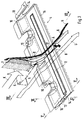
- the air guide element 4 is on a floor panel 5 of the motor vehicle 2, which forms the front region of the underbody 3.
- outlet openings 16 are provided for cooling air.
- a cooling air flow K is passed through a cooler 7.
- the emerging from the cooler 7 heated exhaust air flow 8 is deflected downwards by a second base plate 9, the second Bottom plate 9 in the area of the cooler 7 is pulled up to its upper edge and thus an upper one Limitation of a channel 17 for the exhaust air flow 8 forms.
- An outlet opening 11 of the air guide element 4 is between the second floor panel 9 and one Edge 15 of the air guiding element 4 is formed.
- the air guiding element 4 guides the cooling air flow 8 in such a way that it executes the outlet opening 11 emerges essentially parallel to the underflow U.
- the air guide element 4 consists of a guide surface 12 and side elements 13.
- the guide surface 12 is in its front area, which is attached at one end to the floor panel 5, curved and then goes in a plate-shaped area that ends at the edge 15.
- the side element 13 cover the across Cooling air flow 8 formed gap between the bottom plate 5 and the guide surface 12.
- the guide surface 12 is dimensionally stable, due to the thickness of an elastic deflection of the guide surface 12 transverse to Flow direction of the cooling air flow 8, i.e. perpendicular to the underflow U, is possible.
- the Side elements 13 are made of an elastic material and deformable. In the side elements 13 provided slots 14 (see FIG. 4) additionally support the deformability of the side elements 13. Overall, the guide surface 12 is thus movably held on the underbody 3 of the motor vehicle 2.
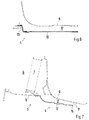
- the edge 15 of the guide surface 12 is at a standstill of the motor vehicle in the designated A Rest position. Their distance from the road 10 is dimensioned such that the bow area 1 of the Motor vehicle 2 does not touch down on embankments during normal maneuvering. At high Driving speeds, however, is caused by the underflow U in the area of the underbody 3 Generates negative pressure, which acts on the guide surface 12 and moves it downward. This takes the edge 15 their second position B. On the one hand, this is due to the stretching of the softly executed Side elements 13 and on the other hand by the deflection of the guide surface 12 in the direction of Underflow U reached. In position B, the outlet opening 11 is enlarged, so that a larger one Cooling air flow 8 is possible. The reduced distance of the edge 15 to the road is in position B. unproblematic, since it can be assumed that high driving speeds on level lanes 10 be driven.
Landscapes
- Engineering & Computer Science (AREA)
- Chemical & Material Sciences (AREA)
- Combustion & Propulsion (AREA)
- Transportation (AREA)
- Mechanical Engineering (AREA)
- Cooling, Air Intake And Gas Exhaust, And Fuel Tank Arrangements In Propulsion Units (AREA)
- Motor Or Generator Cooling System (AREA)
Abstract
Description
- Fig. 1
- eine Seitenansicht eines Bugbereiches eines Kraftfahrzeuges mit einem Luftleitelement,
- Fig. 2
- eine Frontalansicht zu Fig. 1,
- Fig. 3
- eine skizzenhafte Darstellung der Strömungen am Luftleitelement,
- Fig. 4
- eine Seitenansicht des Luftleitelementes,
- Fig. 5
- einen Schnitt nach der Linie V-V der Fig. 3,
- Fig. 6
- einen Schnitt nach der Linie VI-VI der Fig. 3 und
- Fig. 7
- einen Schnitt nach der Linie VII-VII der Fig. 3.
Claims (3)
- Kühlluftführung für Kraftfahrzeuge mit einem in einem Bugbereich (1) eines Kraftfahrzeuges (2) angeordneten Kühler (7), der von einem Kühlluftstrom (K) durchströmt ist, wobei der aus dem Kühler austretende Abluftstrom (8) durch an einem Unterboden (3) angeordnete Auslassöffnungen (16) unter das Kraftfahrzeug geleitet ist und die Auslassöffnungen durch ein Luftleitelement (4) abdeckbar sind, dadurch gekennzeichnet, dass das Luftleitelement (4) den Abluftstrom (8) so umlenkt, dass der Abluftstrom im wesentlichen parallel zu einem am Unterboden (3) vorbeiströmenden Luftstrom (U) ausgerichtet ist.
- Kühlluftführung nach Anspruch 1, dadurch gekennzeichnet, dass das Luftleitelement (4) aus einer Leitfläche (12) und Seitenelementen (13) besteht, wobei die Seitenelemente aus einem elastischen Werkstoff bestehen und die Leitfläche bewegbar am Unterboden (3) des Kraftfahrzeuges (2) befestigt ist.
- Kühlluftführung nach Anspruch 2, dadurch gekennzeichnet, dass die Seitenelemente (13) Schlitze (14) aufweisen.
Applications Claiming Priority (2)
| Application Number | Priority Date | Filing Date | Title |
|---|---|---|---|
| DE10048531 | 2000-09-30 | ||
| DE10048531A DE10048531C1 (de) | 2000-09-30 | 2000-09-30 | Kühlluftführung für Kraftfahrzeuge |
Publications (3)
| Publication Number | Publication Date |
|---|---|
| EP1193167A2 true EP1193167A2 (de) | 2002-04-03 |
| EP1193167A3 EP1193167A3 (de) | 2004-01-02 |
| EP1193167B1 EP1193167B1 (de) | 2006-06-14 |
Family
ID=7658254
Family Applications (1)
| Application Number | Title | Priority Date | Filing Date |
|---|---|---|---|
| EP01116599A Expired - Lifetime EP1193167B1 (de) | 2000-09-30 | 2001-07-10 | Kühlluftführung für Kraftfahrzeuge |
Country Status (4)
| Country | Link |
|---|---|
| US (1) | US6622807B2 (de) |
| EP (1) | EP1193167B1 (de) |
| DE (2) | DE10048531C1 (de) |
| ES (1) | ES2261300T3 (de) |
Cited By (1)
| Publication number | Priority date | Publication date | Assignee | Title |
|---|---|---|---|---|
| CN108116514A (zh) * | 2016-11-28 | 2018-06-05 | 通用汽车环球科技运作有限责任公司 | 气流管理盖 |
Families Citing this family (13)
| Publication number | Priority date | Publication date | Assignee | Title |
|---|---|---|---|---|
| DE10242788B4 (de) * | 2002-09-14 | 2004-09-16 | Dr.Ing.H.C. F. Porsche Ag | Kühleranordnung mit Luftführungskanälen |
| US20060272800A1 (en) * | 2005-06-02 | 2006-12-07 | Paccar Inc | Radiator fan shroud with flow directing ports |
| DE102006014443A1 (de) * | 2006-03-29 | 2007-10-04 | Bayerische Motoren Werke Ag | Frontend für ein Kraftfahrzeug |
| US8221074B2 (en) * | 2007-12-21 | 2012-07-17 | Paccar Inc | Fan ring shroud assembly |
| DE602008006411D1 (de) * | 2008-10-08 | 2011-06-01 | Fiat Ricerche | System zu Steuerung und Führung des Luftstroms durch den Motorraum eines Fahrzeuges |
| US8142553B2 (en) | 2009-10-13 | 2012-03-27 | Caterpillar Inc. | Air cleaner scavenge kit |
| DE102010036440B4 (de) * | 2010-07-16 | 2024-03-28 | Dr. Ing. H.C. F. Porsche Aktiengesellschaft | Kühlluftführung für ein Kraftfahrzeug |
| DE102011113907A1 (de) * | 2011-09-21 | 2012-04-05 | Daimler Ag | Verstellbare Verkleidung für einen Kraftwagen |
| US9188052B2 (en) * | 2011-10-12 | 2015-11-17 | Toyota Jidosha Kabushiki Kaisha | Vehicle front portion structure |
| WO2013088579A1 (ja) * | 2011-12-16 | 2013-06-20 | トヨタ自動車株式会社 | 車両前部構造 |
| US10391856B2 (en) * | 2017-06-23 | 2019-08-27 | Ford Global Technologies Llc | Air deflector with improved drainage |
| US20190016209A1 (en) * | 2017-07-12 | 2019-01-17 | Wesley Langnecker | Air duct apparatus |
| IT201800009561A1 (it) * | 2018-10-18 | 2020-04-18 | Automobili Lamborghini Spa | Dispositivo regolatore di carico aerodinamico per automobile |
Citations (2)
| Publication number | Priority date | Publication date | Assignee | Title |
|---|---|---|---|---|
| DE3150152A1 (de) | 1981-12-18 | 1983-06-30 | Daimler-Benz Ag, 7000 Stuttgart | "spoiler fuer kraftwagen" |
| DE3704145C2 (de) | 1987-02-11 | 1990-08-30 | Adam Opel Ag, 6090 Ruesselsheim, De |
Family Cites Families (17)
| Publication number | Priority date | Publication date | Assignee | Title |
|---|---|---|---|---|
| US1979191A (en) * | 1932-01-05 | 1934-10-30 | Burney Charles Dennistoun | Cooling system for automobiles |
| AT354863B (de) * | 1975-06-13 | 1980-02-11 | List Hans | Kraftfahrzeug mit einer schalldaemmenden kapsel fuer den motor bzw. die motor-getriebe -einheit |
| DE2740918A1 (de) * | 1977-09-10 | 1979-03-22 | Bayerische Motoren Werke Ag | Brennkraftmaschine mit schallisolierender kapsel und ausserhalb der kapsel angeordnetem wasserkuehler |
| DE3211149A1 (de) * | 1982-03-26 | 1983-10-13 | Ford-Werke AG, 5000 Köln | Motorkuehleinrichtung fuer kraftfahrzeuge |
| DE3403156A1 (de) * | 1984-01-31 | 1985-08-08 | Bayerische Motoren Werke AG, 8000 München | Befestigungsanordnung einer aus ringkuehler und kuehlgeblaese bestehenden baueinheit |
| DE3446950C1 (de) * | 1984-12-21 | 1986-05-22 | Bayerische Motoren Werke AG, 8000 München | Steuervorrichtung fuer die Kuehlluft luft-fluessigkeits-gekuehlter Brennkraftmaschinen,insbesondere von Kraftfahrzeugen |
| GB2174652A (en) * | 1985-05-09 | 1986-11-12 | Ford Motor Co | Engine cooling system |
| US4924826A (en) * | 1989-04-27 | 1990-05-15 | Vinson Paul S | Temperature responsive engine compartment |
| JPH05169986A (ja) * | 1991-12-24 | 1993-07-09 | Nissan Motor Co Ltd | エンジンルーム構造 |
| US5526872A (en) * | 1993-10-22 | 1996-06-18 | Ford Motor Company | Airflow ejector for an automotive vehicle |
| DE4343593C2 (de) * | 1993-12-21 | 1998-05-20 | Asta Medica Ag | Verwendung von R-(+)-alpha-Liponsäure, R-(-)-Dihydroliponsäure oder der Metabolite sowie deren Salze, Ester, Amide zur Behandlung kompensierter und dekompensierter Insulinresistenz |
| US5626185A (en) * | 1994-07-05 | 1997-05-06 | Ford Motor Company | Airflow ejector system for an automotive vehicle with wheel-well ejectors |
| JPH09226388A (ja) * | 1996-02-23 | 1997-09-02 | Nissan Motor Co Ltd | 乗用車用エンジンルームの冷却構造 |
| US5724925A (en) * | 1996-12-30 | 1998-03-10 | Usui Kokusai Sangyo Kaisha Ltd. | Wind directing device for automotive engine cooling fan |
| DE19705268C2 (de) * | 1997-02-12 | 1999-10-21 | Porsche Ag | Kraftfahrzeug mit einer bugseitigen Luftführungsvorrichtung |
| EP0888956B1 (de) * | 1997-07-04 | 2002-08-14 | Volkswagen Aktiengesellschaft | Hinterachsennaher Bodenbereich eines Kraftfahrzeugs |
| US6390217B1 (en) * | 2001-04-02 | 2002-05-21 | Delphi Technologies, Inc. | Vehicle front end air control |
-
2000
- 2000-09-30 DE DE10048531A patent/DE10048531C1/de not_active Expired - Fee Related
-
2001
- 2001-07-10 EP EP01116599A patent/EP1193167B1/de not_active Expired - Lifetime
- 2001-07-10 ES ES01116599T patent/ES2261300T3/es not_active Expired - Lifetime
- 2001-07-10 DE DE50110130T patent/DE50110130D1/de not_active Expired - Lifetime
- 2001-10-01 US US09/965,853 patent/US6622807B2/en not_active Expired - Lifetime
Patent Citations (2)
| Publication number | Priority date | Publication date | Assignee | Title |
|---|---|---|---|---|
| DE3150152A1 (de) | 1981-12-18 | 1983-06-30 | Daimler-Benz Ag, 7000 Stuttgart | "spoiler fuer kraftwagen" |
| DE3704145C2 (de) | 1987-02-11 | 1990-08-30 | Adam Opel Ag, 6090 Ruesselsheim, De |
Cited By (2)
| Publication number | Priority date | Publication date | Assignee | Title |
|---|---|---|---|---|
| CN108116514A (zh) * | 2016-11-28 | 2018-06-05 | 通用汽车环球科技运作有限责任公司 | 气流管理盖 |
| CN108116514B (zh) * | 2016-11-28 | 2020-10-16 | 通用汽车环球科技运作有限责任公司 | 气流管理盖 |
Also Published As
| Publication number | Publication date |
|---|---|
| DE50110130D1 (de) | 2006-07-27 |
| ES2261300T3 (es) | 2006-11-16 |
| US6622807B2 (en) | 2003-09-23 |
| US20020038634A1 (en) | 2002-04-04 |
| EP1193167B1 (de) | 2006-06-14 |
| EP1193167A3 (de) | 2004-01-02 |
| DE10048531C1 (de) | 2002-04-25 |
Similar Documents
| Publication | Publication Date | Title |
|---|---|---|
| DE10048531C1 (de) | Kühlluftführung für Kraftfahrzeuge | |
| DE4429924B4 (de) | Unterbodenkonstruktion für ein Fahrzeug | |
| DE19758603C2 (de) | Kraftfahrzeug mit einer heckseitigen Luftleitvorrichtung | |
| DE19527442C2 (de) | Luftleitkanal für eine Kühleinrichtung | |
| DE102014017103B4 (de) | Wasserfangleistenanordnung an einem Fahrzeug, insbesondere an einem Kraftfahrzeug | |
| DE102007022298A1 (de) | Unterbodenverkleidung für ein Kraftfahrzeug | |
| DE102009027475B4 (de) | Luftführungsvorrichtung | |
| DE19935270C2 (de) | Mittelkonsole für Fahrzeuge | |
| DE3130881A1 (de) | "luftstroemungsleitflaeche fuer fahrzeuge" | |
| DE19606506A1 (de) | Fahrzeugaufbau | |
| EP1520771B1 (de) | Aerodynamisch ausgebildetes Verkleidungsteil für die Unterseite eines Kraftfahrzeuges, insbesondere Personenwagens | |
| DE19728265C2 (de) | Vorrichtung zur Belüftung eines Aggregates an einem Fahrzeug | |
| DE102007023231A1 (de) | Luftführungseinrichtung an einem Personenkraftwagen | |
| WO2011091971A1 (de) | Vorderwagen eines fahrzeugs | |
| DE4208999A1 (de) | Aerodynamisches, verstellbares unterbodenfrontende fuer kraftfahrzeuge | |
| DE19525698A1 (de) | Stoßfänger | |
| DE3024312A1 (de) | Frontkonstruktion eines fahrzeuges | |
| EP1045769B1 (de) | Lufteintritt für eine heizungs- oder klimaanlage eines kraftfahrzeuges | |
| DE19806610C2 (de) | Heckspoiler eines Kraftfahrzeuges mit integriertem Ladeluftkühler | |
| DE3630435A1 (de) | Fahrzeugfront mit wenigstens einer lufteintrittsoeffnung auf jeder seite | |
| DE102008011138A1 (de) | Fahrzeug mit einer Fahrzeugklimaanlage mit zweiteiligem Luftkanal | |
| DE9201119U1 (de) | Waschvorrichtung für die Windschutzscheibe eines Kraftfahrzeuges | |
| DE19961316B4 (de) | Kraftfahrzeug mit einer heckseitigen Luftumlenkeinrichtung | |
| DE3941699C1 (de) | ||
| DE102019217285A1 (de) | Unterbodenstruktur für ein Fahrzeug zur Führung eines Luftstroms |
Legal Events
| Date | Code | Title | Description |
|---|---|---|---|
| PUAI | Public reference made under article 153(3) epc to a published international application that has entered the european phase |
Free format text: ORIGINAL CODE: 0009012 |
|
| AK | Designated contracting states |
Kind code of ref document: A2 Designated state(s): AT BE CH CY DE DK ES FI FR GB GR IE IT LI LU MC NL PT SE TR |
|
| AX | Request for extension of the european patent |
Free format text: AL;LT;LV;MK;RO;SI |
|
| PUAL | Search report despatched |
Free format text: ORIGINAL CODE: 0009013 |
|
| AK | Designated contracting states |
Kind code of ref document: A3 Designated state(s): AT BE CH CY DE DK ES FI FR GB GR IE IT LI LU MC NL PT SE TR |
|
| AX | Request for extension of the european patent |
Extension state: AL LT LV MK RO SI |
|
| 17P | Request for examination filed |
Effective date: 20040702 |
|
| AKX | Designation fees paid |
Designated state(s): DE ES FR GB IT |
|
| GRAP | Despatch of communication of intention to grant a patent |
Free format text: ORIGINAL CODE: EPIDOSNIGR1 |
|
| GRAS | Grant fee paid |
Free format text: ORIGINAL CODE: EPIDOSNIGR3 |
|
| GRAA | (expected) grant |
Free format text: ORIGINAL CODE: 0009210 |
|
| AK | Designated contracting states |
Kind code of ref document: B1 Designated state(s): DE ES FR GB IT |
|
| REG | Reference to a national code |
Ref country code: GB Ref legal event code: FG4D Free format text: NOT ENGLISH |
|
| REF | Corresponds to: |
Ref document number: 50110130 Country of ref document: DE Date of ref document: 20060727 Kind code of ref document: P |
|
| GBT | Gb: translation of ep patent filed (gb section 77(6)(a)/1977) |
Effective date: 20060919 |
|
| REG | Reference to a national code |
Ref country code: ES Ref legal event code: FG2A Ref document number: 2261300 Country of ref document: ES Kind code of ref document: T3 |
|
| ET | Fr: translation filed | ||
| PLBE | No opposition filed within time limit |
Free format text: ORIGINAL CODE: 0009261 |
|
| STAA | Information on the status of an ep patent application or granted ep patent |
Free format text: STATUS: NO OPPOSITION FILED WITHIN TIME LIMIT |
|
| 26N | No opposition filed |
Effective date: 20070315 |
|
| REG | Reference to a national code |
Ref country code: ES Ref legal event code: PC2A |
|
| REG | Reference to a national code |
Ref country code: FR Ref legal event code: TP |
|
| PGFP | Annual fee paid to national office [announced via postgrant information from national office to epo] |
Ref country code: ES Payment date: 20090724 Year of fee payment: 9 |
|
| REG | Reference to a national code |
Ref country code: FR Ref legal event code: CD |
|
| REG | Reference to a national code |
Ref country code: FR Ref legal event code: TP |
|
| REG | Reference to a national code |
Ref country code: GB Ref legal event code: 732E Free format text: REGISTERED BETWEEN 20110310 AND 20110316 |
|
| REG | Reference to a national code |
Ref country code: GB Ref legal event code: 732E Free format text: REGISTERED BETWEEN 20110331 AND 20110406 |
|
| REG | Reference to a national code |
Ref country code: ES Ref legal event code: FD2A Effective date: 20111118 |
|
| PG25 | Lapsed in a contracting state [announced via postgrant information from national office to epo] |
Ref country code: ES Free format text: LAPSE BECAUSE OF NON-PAYMENT OF DUE FEES Effective date: 20100711 |
|
| REG | Reference to a national code |
Ref country code: FR Ref legal event code: PLFP Year of fee payment: 16 |
|
| PGFP | Annual fee paid to national office [announced via postgrant information from national office to epo] |
Ref country code: IT Payment date: 20160725 Year of fee payment: 16 Ref country code: GB Payment date: 20160721 Year of fee payment: 16 |
|
| PGFP | Annual fee paid to national office [announced via postgrant information from national office to epo] |
Ref country code: FR Payment date: 20160721 Year of fee payment: 16 |
|
| GBPC | Gb: european patent ceased through non-payment of renewal fee |
Effective date: 20170710 |
|
| REG | Reference to a national code |
Ref country code: FR Ref legal event code: ST Effective date: 20180330 |
|
| PG25 | Lapsed in a contracting state [announced via postgrant information from national office to epo] |
Ref country code: GB Free format text: LAPSE BECAUSE OF NON-PAYMENT OF DUE FEES Effective date: 20170710 |
|
| PG25 | Lapsed in a contracting state [announced via postgrant information from national office to epo] |
Ref country code: FR Free format text: LAPSE BECAUSE OF NON-PAYMENT OF DUE FEES Effective date: 20170731 |
|
| PG25 | Lapsed in a contracting state [announced via postgrant information from national office to epo] |
Ref country code: IT Free format text: LAPSE BECAUSE OF NON-PAYMENT OF DUE FEES Effective date: 20170710 |
|
| PGFP | Annual fee paid to national office [announced via postgrant information from national office to epo] |
Ref country code: DE Payment date: 20180710 Year of fee payment: 18 |
|
| REG | Reference to a national code |
Ref country code: DE Ref legal event code: R119 Ref document number: 50110130 Country of ref document: DE |
|
| PG25 | Lapsed in a contracting state [announced via postgrant information from national office to epo] |
Ref country code: DE Free format text: LAPSE BECAUSE OF NON-PAYMENT OF DUE FEES Effective date: 20200201 |