EP1192071B1 - Service brake actuator having a unitary pushrod assembly with a bushing therefor - Google Patents
Service brake actuator having a unitary pushrod assembly with a bushing therefor Download PDFInfo
- Publication number
- EP1192071B1 EP1192071B1 EP00930606A EP00930606A EP1192071B1 EP 1192071 B1 EP1192071 B1 EP 1192071B1 EP 00930606 A EP00930606 A EP 00930606A EP 00930606 A EP00930606 A EP 00930606A EP 1192071 B1 EP1192071 B1 EP 1192071B1
- Authority
- EP
- European Patent Office
- Prior art keywords
- shaft
- opening
- pushrod
- brake actuator
- bushing
- Prior art date
- Legal status (The legal status is an assumption and is not a legal conclusion. Google has not performed a legal analysis and makes no representation as to the accuracy of the status listed.)
- Expired - Lifetime
Links
- 230000008878 coupling Effects 0.000 claims description 17
- 238000010168 coupling process Methods 0.000 claims description 17
- 238000005859 coupling reaction Methods 0.000 claims description 17
- 238000000034 method Methods 0.000 claims description 10
- 238000003780 insertion Methods 0.000 claims description 7
- 230000037431 insertion Effects 0.000 claims description 7
- 239000012530 fluid Substances 0.000 claims description 3
- 238000000926 separation method Methods 0.000 claims description 2
- 230000006835 compression Effects 0.000 description 5
- 238000007906 compression Methods 0.000 description 5
- 238000009434 installation Methods 0.000 description 2
- 238000004519 manufacturing process Methods 0.000 description 2
- 229920004943 Delrin® Polymers 0.000 description 1
- 230000002860 competitive effect Effects 0.000 description 1
- 238000010276 construction Methods 0.000 description 1
- 230000001186 cumulative effect Effects 0.000 description 1
- 230000002452 interceptive effect Effects 0.000 description 1
- 230000002093 peripheral effect Effects 0.000 description 1
- 238000007789 sealing Methods 0.000 description 1
- 238000003466 welding Methods 0.000 description 1
Images


Classifications
-
- B—PERFORMING OPERATIONS; TRANSPORTING
- B60—VEHICLES IN GENERAL
- B60T—VEHICLE BRAKE CONTROL SYSTEMS OR PARTS THEREOF; BRAKE CONTROL SYSTEMS OR PARTS THEREOF, IN GENERAL; ARRANGEMENT OF BRAKING ELEMENTS ON VEHICLES IN GENERAL; PORTABLE DEVICES FOR PREVENTING UNWANTED MOVEMENT OF VEHICLES; VEHICLE MODIFICATIONS TO FACILITATE COOLING OF BRAKES
- B60T17/00—Component parts, details, or accessories of power brake systems not covered by groups B60T8/00, B60T13/00 or B60T15/00, or presenting other characteristic features
- B60T17/08—Brake cylinders other than ultimate actuators
- B60T17/085—Spring loaded brake actuators
-
- B—PERFORMING OPERATIONS; TRANSPORTING
- B60—VEHICLES IN GENERAL
- B60T—VEHICLE BRAKE CONTROL SYSTEMS OR PARTS THEREOF; BRAKE CONTROL SYSTEMS OR PARTS THEREOF, IN GENERAL; ARRANGEMENT OF BRAKING ELEMENTS ON VEHICLES IN GENERAL; PORTABLE DEVICES FOR PREVENTING UNWANTED MOVEMENT OF VEHICLES; VEHICLE MODIFICATIONS TO FACILITATE COOLING OF BRAKES
- B60T17/00—Component parts, details, or accessories of power brake systems not covered by groups B60T8/00, B60T13/00 or B60T15/00, or presenting other characteristic features
- B60T17/08—Brake cylinders other than ultimate actuators
- B60T17/083—Combination of service brake actuators with spring loaded brake actuators
Definitions
- This invention relates to an improvement in a service brake actuator for air-operated vehicle brakes; and, more particularly, to a service brake actuator having a unitary pushrod assembly with a separable bushing capable of being assembled about the pushrod for sealing the pushrod with respect to the service brake actuator.
- Air-operated brake actuators are well known in the vehicle industry, especially in the heavy-duty truck industry where the air-operated brake actuators are controlled by a source of pressurized air to apply the operational brakes and emergency brakes of the heavy-duty truck and/or trailer.
- a typical air-operated brake actuator comprises a spring brake actuator in combination with a service brake actuator.
- the service brake actuator comprises a housing that is divided into a pressure chamber and a pushrod chamber in which is disposed one portion of a pushrod assembly.
- the pushrod assembly includes a pressure plate mounted on one end of the pushrod and adapted to abut the diaphragm.
- a clevis is mounted to the other end of the pushrod and is adapted to connect to a brake lever.
- the reciprocation of the pushrod with respect to the housing moves the brake lever to apply or release the brakes, depending on the direction of movement.
- Pressurized air is introduced into the service brake pressure chamber to move the position of the diaphragm and thereby reciprocate the pushrod assembly, resulting in the application or release of the brake, depending on the amount of air introduced or exhausted from the service brake pressure chamber.
- the spring brake actuator has a similar construction to that of the service brake actuator in that it typically includes a diaphragm dividing the spring brake actuator into a spring chamber and a pressure chamber.
- a large force compression spring is housed within the spring chamber between the housing and the diaphragm and is typically separated from the diaphragm by a pressure plate in abutting relationship with the diaphragm.
- An actuating rod extends from the pressure plate through the diaphragm and into the service brake pressure chamber. The introduction of compressed air into the spring brake pressure chamber compresses the spring and withdraws the actuator from contact with the service brake diaphragm.
- the pressurized air is exhausted from the spring brake pressure chamber whereby the large force compression spring expands, bringing the actuator into contact with the diaphragm to extend the pushrod from the service brake actuator and apply the brakes.
- the pushrod and the clevis of the pushrod assembly are typically assembled after the pushrod has been inserted through an opening in the service brake actuator housing by threading a tapped opening of the clevis onto a threaded end of the pushrod and fixing the relative position of the clevis and pushrod by one or more lock nuts or the clevis was welded to pushrod end.
- a bushing encircled the pushrod and sealed the pushrod relative to the housing opening through which the pushrod reciprocated.
- the bushing included a body sized to fit within the service brake opening and a flange sized to abut the service brake housing.
- a pushrod opening extended through the body. The return spring bore against the bushing to bias the bushing against the service brake housing.
- the clevis could not be mounted onto the end of the pushrod prior to the insertion of the pushrod through the housing because the clevis is too large to pass through pushrod opening in the bushing, although it is small enough to pass through the housing opening.
- DE 39 35 663 A1 shows an air-operated brake actuator with a first fluid pressure chamber and a second fluid pressure chamber wherein one chamber is spanned by a diaphragm.
- the diaphragm is connected to a piston welded to a pushrod holding a clevis at the end opposite to the piston.
- the pushrod is supported by the diaphragm and the elastic bellow wherein the bellow is closed in circumferential direction.
- One axial end of the bellow is fixed to the pushrod whereas the other axial end of the bellow is fixed to the housing of the chamber associated with the piston.
- the bellow is expanded in axial direction.
- the pushrod does not comprise any exact guidance in radial direction with respect to the housing.
- DE 36 03 145 A1 discloses an air-operated break actuator comprising only one chamber wherein the chamber is spanned by a diaphragm cooperating with a piston connected to a pushrod.
- the housing comprises an opening.
- a screw divided in a mid plain into two parts is screwed into the housing in the area of the opening.
- the screw comprises a radial flange serving as an end stop for an end position of the pushrod.
- the invention relates to an air-operated brake actuator for applying and releasing a brake comprising a housing having first and second portion portions between which is positioned a diaphragm, dividing the interior of the housing into a pushrod chamber and a pressure chamber.
- the housing second portion has a pushrod opening that extends between the pushrod chamber and the exterior of the housing.
- a pushrod comprising a shaft having first and second ends, a pressure plate mounted on the first end of the shaft, and a coupling mounted on the second end of the shaft, is mounted within the pushrod chamber such that the pressure plate lies within the pressure chamber, the shaft extends through the pushrod opening, and the coupling is located exteriorly of the second portion.
- the coupling has a maximum dimension sized to permit passage through the pushrod opening.
- a bushing encircles the shaft and is positioned within the pushrod opening.
- the bushing comprises a body sized to be received within the pushrod opening and a shaft opening in the body for receiving the shaft.
- the bushing has at least one separable portion that enables radial access to the shaft opening, thereby permitting the assembly of the bushing to the shaft after the clevis and pressure plate are mounted to the shaft.
- the shaft opening maximum dimension is sized to prohibit the passage of the coupling therethrough.
- the bushing can comprise two arcuate portions which when assembled form the body with an outer circumferential portion received within the pushrod opening and an inner circumferential portion forming the shaft opening. Each arcuate portion can terminate in opposing end portions, with one end portion having a key and the other end portion having a keyhole sized to receive the key to couple together the arcuate portions.
- the arcuate portions can further include a flange extending beyond the body and which abuts the interior of the housing second portion when the body is received within the pushrod opening.
- the invention in another aspect, relates to a method of assembling an air operated brake actuator comprising a housing having an first portion and a second portion, with a pushrod opening in the second portion.
- a diaphragm spans the housing dividing the housing into a pushrod chamber and a pressure chamber.
- a pushrod is partially received within the pushrod chamber.
- the pushrod comprises a shaft, a pressure plate mounted on one end of the shaft, and a coupling mounted on another end of the shaft.
- the coupling has a maximum dimension sized to permit passage through the pushrod opening.
- a bushing having a body sized to be received within the pushrod opening and a shaft opening in the body. The bushing comprises at least one portion that is separable from the bushing a sufficient amount to permit the radial insertion of the shaft into the shaft opening.
- the method comprising the steps inserting the coupling through the pushrod opening, separating the seperable portion from the bushing to form a radial passage to the pushrod opening, inserting the shaft into the shaft opening through the radial opening, positioning the body in the actuator opening, positioning the diaphragm between the first and second housing portions, and securing the first and second housing portions together.
- the step of inserting of the shaft into the shaft opening precedes the insertion of the coupling through the pushrod opening.
- the separable portion is then assembled to the body.
- the assembly of the separable body portion includes inserting a key on each of the parts into a corresponding keyhole on another part.
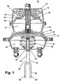
- FIG. 1 illustrates an air-operated brake actuator 10 comprising a spring brake actuator 12 in combination with a service brake actuator 14.
- the spring brake actuator 12 and service brake actuator 14 both share a common adapter housing 16, which forms a portion of the housing for each of the spring brake actuator 12 and the service brake actuator 14.
- the spring brake actuator 12 further comprises a cup-shaped head 18 that connects to the adapter housing 16 to form the housing for the spring brake actuator.
- a diaphragm 20 is trapped between the joined edges of the head and the adapter housing 16 to divide the spring brake actuator 12 into a spring chamber 22 and a pressure chamber 24.
- a large force compression spring 26 is disposed within the spring chamber 22 between the head 18 and a pressure plate 28 abutting the diaphragm 20.
- the pressure plate 28 mounts a hollow actuator rod 30, which extends through the diaphragm 20 and into the upper portion of the service brake actuator 14.
- the pressure chamber 24 is fluidly connected to a source of compressed air (not shown).
- a source of compressed air not shown.
- the introduction of the compressed air into the pressure chamber 24 moves the diaphragm 20 and pressure plate 28 upwardly to compress or cage the large force compression spring 26 against the head.
- the actuator rod 30 is withdrawn to its uppermost position with respect to the service brake actuator 14.
- the actuator rod 30 extends its greatest distance into the service brake actuator 14.
- the service brake actuator 14 comprises a housing 16 formed by a cup-shaped bottom housing 34 that is connected to the adapter housing 16.
- a diaphragm 36 is trapped between the joined edges of the bottom housing 34 and the adapter housing 16 to divide the service brake actuator 14 into a pressure chamber 38 and a pushrod chamber 40.
- the pressure chamber 38 is connected to a source of compressed air (not shown) and operates in a similar manner as described above with respect to the spring brake actuator pressure chamber 24.
- a pushrod assembly 42 is partially disposed within the pushrod chamber.
- the pushrod assembly comprises a shaft 44 having one end mounted to a pressure plate 46 and a clevis 48 welded to the other end of the shaft 44.
- a return spring 50 is disposed between the bottom housing 34 and the pressure plate 46 to urge the pushrod assembly 42 toward the dividing wall of the adapter housing 16.
- a bushing 62 is positioned within an opening in the bottom housing 34 and receives the shaft 44 through a shaft opening 64 to seal the pushrod chamber with respect to the shaft 44 while providing a bearing surface for the reciprocating movement of the shaft 44 during normal operation.
- the return spring 50 biases the bushing 62 into contact with the bottom housing 34.
- the clevis 48 has a generally U-shaped cross section and comprises opposing fingers 52 connected by a bight portion 54. A pair of openings 56, 58 are provided in each of the fingers 52 for use in connecting the clevis 48 to the lever of a brake system, such as an S-cam brake assembly.
- the end of the shaft 44 abuts and is welded to the bight portion 54 of the clevis 48.
- the clevis 48 and shaft 44 extend through a pushrod opening 60 in the bottom housing 34.
- the bushing 62 has a body 68 in which is defined the axially oriented shaft opening 64.
- An annular shoulder 70 extends from the bushing body 68 and is greater in diameter than the bottom housing opening 34.
- the body 68 is effectively divided by the shoulder 70 so that the housing side 72 of the body 68 has a greater diameter than the pushrod chamber side 74.
- the shaft opening 64 is tapered at the pushrod chamber side 74 so as not to provide a sharp edge within the stroke path of the shaft 44.
- the bushing 62 is formed from two pieces, which are generally illustrated as arcuate segments 66, preferably half a circle, which terminate in ends 76.
- a protrusion or key 78 extends from the ends of each of the bushing halves.
- a blind opening or keyhole 80 extends into the opposite end of each half so that the key 78 of one half is received within the keyhole 80 of the other half to fix the relative positions of the two halves when assembled.
- the service brake actuator 14 is assembled by sliding the clevis 48 and shaft of the unitary pushrod assembly through the coil return spring 50 and inserting the shaft 44 and clevis 48 through the bottom housing opening 34 until the clevis 48 extends through the bottom housing 34.
- the two halves 66 of the bushing 62 are positioned on opposite sides of the shaft 44 and pressed together until the keys 78 are received in the corresponding keyhole 80.
- the separability of the two halves effectively permits the shaft to be inserted radially into the shaft opening.
- the housing side of the bushing 62 is inserted within the bushing opening.
- the pushrod assembly 42 is drawn towards the bottom housing 34 to effectively cage the spring and remove the pressure plate 46 from interfering with the positioning of the diaphragm 36 between the adapter housing 16 and the bottom housing 34, which are clamped together with the peripheral edge of the diaphragm held therebetween to complete the assembly.
- FIG. 5 illustrates a second embodiment bushing 82 that is substantially similar to the bushing 62 in that the bushing 82 comprises arcuate portions 86, which, when assembled form a body 88 having an annular shoulder 90 and an axial shaft opening 84.
- the main difference between the second embodiment bushing 82 and first embodiment bushing 62 is that the arcuate portions 86 are connected by a hinge 101, permitting the separation of the arcuate portions 86 by pivoting the arcuate portions relative to the hinge 101.
- the hinge is preferably a living hinge integrally formed with the arcuate portions but could be any other suitable structure, including a mechanical connection such as tape.
- the hinge 101 is a living hinge extending between adjacent portions of the annular shoulder.
- the ends of the arcuate portions opposite the hinge include a key 98 and a keyhole 100, respectively.
- the separability of the arcuate portions 86 of the bushing 82 permit the bushing to be assembled about the shaft 44 after the pressure plate 46 and clevis 48 are mounted to the shaft.
- the assembly of the bushing to the shaft merely requires the arcuate portions 86 to be rotated about the hinge 101 until the arcuate portions are separated a sufficient distance that the shaft 44 can be radially inserted into the pushrod shaft opening 84 of the bushing 82.
- the arcuate portions 86 are then rotated toward each other until the key 98 is received within the keyhole 100.
- the bushing 82 can be slid along the shaft 44 until it is positioned within the shaft opening 60.
- FIG. 6 illustrates a third embodiment bushing 102 that is substantially similar to the bushings 62, 82 in that the bushing 102 comprises a body having defining a shaft opening.
- the main difference between the third embodiment bushing 82 and first and second embodiment bushings is that the body 108 is not formed by physically distinct arcuate portions, but is formed by a ring 103 having a slit 105 defined by opposing end surfaces 116.
- the ring can be thought of as having two conceptual arcuate portions 106 with one of their ends permanently connected and the other end being formed by the end surfaces 116.
- the end surfaces 116 are preferably oriented at an angle relative to the axis of the shaft opening 104.
- the arcuate portions are grasped near the end surfaces and moved axially in opposite directions, as indicated by the direction arrows in FIG. 6, separating the ends a sufficient distance for the shaft 44 to be radially received between the end surfaces and into the shaft opening.
- the end surfaces 116 are released and the inherently resiliency of the bushing 102, which is preferably made of Delrin, results in the end surfaces returning substantially to their undeflected postion.
- the force of the return spring 50 is sufficient to bias the end surfaces into contact when the brake is assembled.
- the bushing can be assembled to the shaft after the insertion of the shaft and clevis through the return spring but before the insertion of the clevis through the bushing opening.
- the invention reduces the number of steps involved in assembling the service brake actuator by permitting the installation of a unitary pushrod assembly because of the multi-piece structure of the bushing.
- the simplification of the service brake actuator assembly advantageously reduces the complexity of the pushrod assembly in that it is no longer needed since the clevis can now be fixedly secured to the shaft, preferably by welding, instead of removably secured as found in the prior art service brake actuators, reducing the part count.
- the cumulative advantages associated with the multi-piece bushing results in a service brake actuator having reduced part count and a quicker assembly time, both of which provide a competitive advantage.
Landscapes
- Engineering & Computer Science (AREA)
- Transportation (AREA)
- Mechanical Engineering (AREA)
- Braking Arrangements (AREA)
- Braking Systems And Boosters (AREA)
Description
- This invention relates to an improvement in a service brake actuator for air-operated vehicle brakes; and, more particularly, to a service brake actuator having a unitary pushrod assembly with a separable bushing capable of being assembled about the pushrod for sealing the pushrod with respect to the service brake actuator.
- Air-operated brake actuators are well known in the vehicle industry, especially in the heavy-duty truck industry where the air-operated brake actuators are controlled by a source of pressurized air to apply the operational brakes and emergency brakes of the heavy-duty truck and/or trailer. A typical air-operated brake actuator comprises a spring brake actuator in combination with a service brake actuator. The service brake actuator comprises a housing that is divided into a pressure chamber and a pushrod chamber in which is disposed one portion of a pushrod assembly.
- The pushrod assembly includes a pressure plate mounted on one end of the pushrod and adapted to abut the diaphragm. A clevis is mounted to the other end of the pushrod and is adapted to connect to a brake lever. The reciprocation of the pushrod with respect to the housing moves the brake lever to apply or release the brakes, depending on the direction of movement. Pressurized air is introduced into the service brake pressure chamber to move the position of the diaphragm and thereby reciprocate the pushrod assembly, resulting in the application or release of the brake, depending on the amount of air introduced or exhausted from the service brake pressure chamber.
- The spring brake actuator has a similar construction to that of the service brake actuator in that it typically includes a diaphragm dividing the spring brake actuator into a spring chamber and a pressure chamber. A large force compression spring is housed within the spring chamber between the housing and the diaphragm and is typically separated from the diaphragm by a pressure plate in abutting relationship with the diaphragm. An actuating rod extends from the pressure plate through the diaphragm and into the service brake pressure chamber. The introduction of compressed air into the spring brake pressure chamber compresses the spring and withdraws the actuator from contact with the service brake diaphragm. When it is desired to apply the parking brakes or the emergency brakes, the pressurized air is exhausted from the spring brake pressure chamber whereby the large force compression spring expands, bringing the actuator into contact with the diaphragm to extend the pushrod from the service brake actuator and apply the brakes.
- In prior service brake actuators, such as that disclosed in
U.S. Patent No. 5,002,164, issued March 26, 1991 , which is incorporated by reference, the pushrod and the clevis of the pushrod assembly are typically assembled after the pushrod has been inserted through an opening in the service brake actuator housing by threading a tapped opening of the clevis onto a threaded end of the pushrod and fixing the relative position of the clevis and pushrod by one or more lock nuts or the clevis was welded to pushrod end. A bushing encircled the pushrod and sealed the pushrod relative to the housing opening through which the pushrod reciprocated. The bushing included a body sized to fit within the service brake opening and a flange sized to abut the service brake housing. A pushrod opening extended through the body. The return spring bore against the bushing to bias the bushing against the service brake housing. - In the prior art, the clevis could not be mounted onto the end of the pushrod prior to the insertion of the pushrod through the housing because the clevis is too large to pass through pushrod opening in the bushing, although it is small enough to pass through the housing opening.
- Given the high volume and great price competitiveness of the air-operated brake actuator marketplace, there is a continuous desire to simplify the manufacture and assembly of the air-operated brake actuators. To that end, there is a desire to manufacture and/or assemble the pushrod assembly into a unitary element prior to installation of the pushrod assembly, preventing the use of the current bushing.
-
DE 39 35 663 A1 shows an air-operated brake actuator with a first fluid pressure chamber and a second fluid pressure chamber wherein one chamber is spanned by a diaphragm. The diaphragm is connected to a piston welded to a pushrod holding a clevis at the end opposite to the piston. The pushrod is supported by the diaphragm and the elastic bellow wherein the bellow is closed in circumferential direction. One axial end of the bellow is fixed to the pushrod whereas the other axial end of the bellow is fixed to the housing of the chamber associated with the piston. During axial movement of the pushrod the bellow is expanded in axial direction. The pushrod does not comprise any exact guidance in radial direction with respect to the housing. -
DE 36 03 145 A1 discloses an air-operated break actuator comprising only one chamber wherein the chamber is spanned by a diaphragm cooperating with a piston connected to a pushrod. The housing comprises an opening. A screw divided in a mid plain into two parts is screwed into the housing in the area of the opening. The screw comprises a radial flange serving as an end stop for an end position of the pushrod. - The invention relates to an air-operated brake actuator for applying and releasing a brake comprising a housing having first and second portion portions between which is positioned a diaphragm, dividing the interior of the housing into a pushrod chamber and a pressure chamber. The housing second portion has a pushrod opening that extends between the pushrod chamber and the exterior of the housing. A pushrod comprising a shaft having first and second ends, a pressure plate mounted on the first end of the shaft, and a coupling mounted on the second end of the shaft, is mounted within the pushrod chamber such that the pressure plate lies within the pressure chamber, the shaft extends through the pushrod opening, and the coupling is located exteriorly of the second portion. The coupling has a maximum dimension sized to permit passage through the pushrod opening. A bushing encircles the shaft and is positioned within the pushrod opening. The bushing comprises a body sized to be received within the pushrod opening and a shaft opening in the body for receiving the shaft. The bushing has at least one separable portion that enables radial access to the shaft opening, thereby permitting the assembly of the bushing to the shaft after the clevis and pressure plate are mounted to the shaft.
- Preferably, the shaft opening maximum dimension is sized to prohibit the passage of the coupling therethrough. The bushing can comprise two arcuate portions which when assembled form the body with an outer circumferential portion received within the pushrod opening and an inner circumferential portion forming the shaft opening. Each arcuate portion can terminate in opposing end portions, with one end portion having a key and the other end portion having a keyhole sized to receive the key to couple together the arcuate portions. The arcuate portions can further include a flange extending beyond the body and which abuts the interior of the housing second portion when the body is received within the pushrod opening.
- In another aspect, the invention relates to a method of assembling an air operated brake actuator comprising a housing having an first portion and a second portion, with a pushrod opening in the second portion. A diaphragm spans the housing dividing the housing into a pushrod chamber and a pressure chamber. A pushrod is partially received within the pushrod chamber. The pushrod comprises a shaft, a pressure plate mounted on one end of the shaft, and a coupling mounted on another end of the shaft. The coupling has a maximum dimension sized to permit passage through the pushrod opening. A bushing having a body sized to be received within the pushrod opening and a shaft opening in the body. The bushing comprises at least one portion that is separable from the bushing a sufficient amount to permit the radial insertion of the shaft into the shaft opening.
- The method comprising the steps inserting the coupling through the pushrod opening, separating the seperable portion from the bushing to form a radial passage to the pushrod opening, inserting the shaft into the shaft opening through the radial opening, positioning the body in the actuator opening, positioning the diaphragm between the first and second housing portions, and securing the first and second housing portions together.
- Preferably, the step of inserting of the shaft into the shaft opening precedes the insertion of the coupling through the pushrod opening. The separable portion is then assembled to the body. The assembly of the separable body portion includes inserting a key on each of the parts into a corresponding keyhole on another part.
- In the drawings:
- FIG. I is a sectional view of the combination spring brake actuator and service brake actuator including unitary pushrod assembly in combination with the bushing according to the invention;
- FIG. 2 is an assembly view of the service brake actuator of FIG. 1;
- FIG. 3 is a perspective view of the pushrod assembly of FIG. 1;
- FIG. 4 is a perspective view of the bushing of FIG. 1;
- FIG. 5 is a perspective view of a second embodiment of the bushing according to the invention; and
- FIG. 6 is a perspective view of a third embodiment of the bushing according to the invention.
- FIG. 1 illustrates an air-operated
brake actuator 10 comprising aspring brake actuator 12 in combination with aservice brake actuator 14. In the particular structure shown in FIG. 1, thespring brake actuator 12 andservice brake actuator 14 both share acommon adapter housing 16, which forms a portion of the housing for each of thespring brake actuator 12 and theservice brake actuator 14. - The
spring brake actuator 12 further comprises a cup-shapedhead 18 that connects to theadapter housing 16 to form the housing for the spring brake actuator. Adiaphragm 20 is trapped between the joined edges of the head and theadapter housing 16 to divide thespring brake actuator 12 into aspring chamber 22 and apressure chamber 24. - A large
force compression spring 26 is disposed within thespring chamber 22 between thehead 18 and apressure plate 28 abutting thediaphragm 20. Thepressure plate 28 mounts ahollow actuator rod 30, which extends through thediaphragm 20 and into the upper portion of theservice brake actuator 14. - The
pressure chamber 24 is fluidly connected to a source of compressed air (not shown). The introduction of the compressed air into thepressure chamber 24 moves thediaphragm 20 andpressure plate 28 upwardly to compress or cage the largeforce compression spring 26 against the head. When the largeforce compression spring 26 is caged, theactuator rod 30 is withdrawn to its uppermost position with respect to theservice brake actuator 14. When the pressurized air in thepressure chamber 24 is exhausted, theactuator rod 30 extends its greatest distance into theservice brake actuator 14. - The
service brake actuator 14 comprises ahousing 16 formed by a cup-shapedbottom housing 34 that is connected to theadapter housing 16. Adiaphragm 36 is trapped between the joined edges of thebottom housing 34 and theadapter housing 16 to divide theservice brake actuator 14 into apressure chamber 38 and apushrod chamber 40. Thepressure chamber 38 is connected to a source of compressed air (not shown) and operates in a similar manner as described above with respect to the spring brakeactuator pressure chamber 24. - A
pushrod assembly 42 is partially disposed within the pushrod chamber. The pushrod assembly comprises ashaft 44 having one end mounted to apressure plate 46 and aclevis 48 welded to the other end of theshaft 44. - A
return spring 50 is disposed between thebottom housing 34 and thepressure plate 46 to urge thepushrod assembly 42 toward the dividing wall of theadapter housing 16. Abushing 62 is positioned within an opening in thebottom housing 34 and receives theshaft 44 through ashaft opening 64 to seal the pushrod chamber with respect to theshaft 44 while providing a bearing surface for the reciprocating movement of theshaft 44 during normal operation. Thereturn spring 50 biases thebushing 62 into contact with thebottom housing 34. - The
clevis 48 has a generally U-shaped cross section and comprises opposingfingers 52 connected by abight portion 54. A pair ofopenings fingers 52 for use in connecting theclevis 48 to the lever of a brake system, such as an S-cam brake assembly. The end of theshaft 44 abuts and is welded to thebight portion 54 of theclevis 48. Theclevis 48 andshaft 44 extend through apushrod opening 60 in thebottom housing 34. - The
bushing 62 has abody 68 in which is defined the axially orientedshaft opening 64. Anannular shoulder 70 extends from thebushing body 68 and is greater in diameter than thebottom housing opening 34. Thebody 68 is effectively divided by theshoulder 70 so that thehousing side 72 of thebody 68 has a greater diameter than thepushrod chamber side 74. Also, theshaft opening 64 is tapered at thepushrod chamber side 74 so as not to provide a sharp edge within the stroke path of theshaft 44. - The
bushing 62 is formed from two pieces, which are generally illustrated asarcuate segments 66, preferably half a circle, which terminate in ends 76. A protrusion or key 78 extends from the ends of each of the bushing halves. A blind opening orkeyhole 80 extends into the opposite end of each half so that the key 78 of one half is received within thekeyhole 80 of the other half to fix the relative positions of the two halves when assembled. - Referring to FIG. 2. the
service brake actuator 14 is assembled by sliding theclevis 48 and shaft of the unitary pushrod assembly through thecoil return spring 50 and inserting theshaft 44 andclevis 48 through thebottom housing opening 34 until theclevis 48 extends through thebottom housing 34. In this position, the twohalves 66 of thebushing 62 are positioned on opposite sides of theshaft 44 and pressed together until thekeys 78 are received in the correspondingkeyhole 80. The separability of the two halves effectively permits the shaft to be inserted radially into the shaft opening. The housing side of thebushing 62 is inserted within the bushing opening. Thepushrod assembly 42 is drawn towards thebottom housing 34 to effectively cage the spring and remove thepressure plate 46 from interfering with the positioning of thediaphragm 36 between theadapter housing 16 and thebottom housing 34, which are clamped together with the peripheral edge of the diaphragm held therebetween to complete the assembly. - FIG. 5 illustrates a second embodiment bushing 82 that is substantially similar to the
bushing 62 in that thebushing 82 comprisesarcuate portions 86, which, when assembled form abody 88 having anannular shoulder 90 and anaxial shaft opening 84. The main difference between the second embodiment bushing 82 andfirst embodiment bushing 62 is that thearcuate portions 86 are connected by ahinge 101, permitting the separation of thearcuate portions 86 by pivoting the arcuate portions relative to thehinge 101. The hinge is preferably a living hinge integrally formed with the arcuate portions but could be any other suitable structure, including a mechanical connection such as tape. In the preferred form, thehinge 101 is a living hinge extending between adjacent portions of the annular shoulder. The ends of the arcuate portions opposite the hinge include a key 98 and akeyhole 100, respectively. - The separability of the
arcuate portions 86 of thebushing 82 permit the bushing to be assembled about theshaft 44 after thepressure plate 46 andclevis 48 are mounted to the shaft. The assembly of the bushing to the shaft merely requires thearcuate portions 86 to be rotated about thehinge 101 until the arcuate portions are separated a sufficient distance that theshaft 44 can be radially inserted into the pushrod shaft opening 84 of thebushing 82. Thearcuate portions 86 are then rotated toward each other until the key 98 is received within thekeyhole 100. With the bushing now assembled around theshaft 44, thebushing 82 can be slid along theshaft 44 until it is positioned within theshaft opening 60. - FIG. 6 illustrates a third embodiment bushing 102 that is substantially similar to the
bushings bushing 102 comprises a body having defining a shaft opening. The main difference between thethird embodiment bushing 82 and first and second embodiment bushings is that thebody 108 is not formed by physically distinct arcuate portions, but is formed by aring 103 having aslit 105 defined by opposing end surfaces 116. The ring can be thought of as having two conceptualarcuate portions 106 with one of their ends permanently connected and the other end being formed by the end surfaces 116. The end surfaces 116 are preferably oriented at an angle relative to the axis of theshaft opening 104. Thus, when thebushing 102 is assembled, the return spring will bias the end surfaces 116 together to seal theslit 105 and prevent the ingress contaminates into the pushrod chamber. - To assemble the bushing about the shaft of the pushrod, the arcuate portions are grasped near the end surfaces and moved axially in opposite directions, as indicated by the direction arrows in FIG. 6, separating the ends a sufficient distance for the
shaft 44 to be radially received between the end surfaces and into the shaft opening. Once theshaft 44 is inserted, the end surfaces 116 are released and the inherently resiliency of thebushing 102, which is preferably made of Delrin, results in the end surfaces returning substantially to their undeflected postion. To the extent the end surfaces 116 do not completely return to their undeflected position, the force of thereturn spring 50 is sufficient to bias the end surfaces into contact when the brake is assembled. - One of many alternatives to the above-described assembly is that the bushing can be assembled to the shaft after the insertion of the shaft and clevis through the return spring but before the insertion of the clevis through the bushing opening.
- Regardless of the point at which the bushing is assembled to the unitary pushrod assembly, the invention reduces the number of steps involved in assembling the service brake actuator by permitting the installation of a unitary pushrod assembly because of the multi-piece structure of the bushing. The simplification of the service brake actuator assembly advantageously reduces the complexity of the pushrod assembly in that it is no longer needed since the clevis can now be fixedly secured to the shaft, preferably by welding, instead of removably secured as found in the prior art service brake actuators, reducing the part count. The cumulative advantages associated with the multi-piece bushing results in a service brake actuator having reduced part count and a quicker assembly time, both of which provide a competitive advantage.
- While the invention has been specifically described in connection with certain specific embodiments thereof, it is to be understood that this is by way of illustration and not of limitation, and the scope of the appended claims should be construed as broadly as the prior art will permit.
Claims (24)
- An air-operated brake actuator for applying and releasing a brake, the brake actuator comprising:a housing having a first portion (16) and a second portion (34), with an pushrod opening (60) in the second portion (34);a diaphragm (36) spanning the housing and dividing the interior of the housing into a pushrod chamber (40) and pressure chamber (38) for receiving and exhausting pressurized fluid to apply and release the brakes;a pushrod (42) comprising a shaft (44) having first and second ends, a pressure plate (46) mounted on the first end of the shaft (44), and a coupling (48) mounted on the second end of the shaft (44), the pressure plate (46) being located within the pressure chamber (38), the shaft (44) extending through the pushrod opening (60), and the coupling (48) located exteriorly of the second portion (34) and having a maximum dimension sized to permit passage through the pushrod opening (60); characterized bya bushing (62) defining a body (68) sized to be received within the pushrod opening (60) and a shaft opening (64) in the body (68) for receiving the shaft (44) and comprising at least one portion (66) that is separable from another portion of the bushing (62) to enable radial access to the shaft opening (64), enabling the assembly of the bushing (62) to the shaft (44) after the coupling (48) and pressure plate (46) are mounted to the shaft (44).
- The air-operated brake actuator according to claim 1, wherein the shaft opening maximum dimension is sized to prohibit the passage of the coupling.
- The air-operated brake actuator according to claim 2, wherein the coupling is a clevis (48).
- The air-operated brake actuator according to claim 3, wherein the clevis (48) is U-shaped and comprises parallel sides connected by a bight portion (54), which is connected to the end of the shaft.
- The air-operated brake actuator (10) according to claim 1. wherein the bushing comprises two arcuate portions (62), which when assembled form the body (68) with an outer circumferential portion received within the pushrod opening and an inner circumferential portion forming the shaft opening.
- The air-operated brake actuator according to claim 5, wherein each arcuate portion terminates in opposing end portions, with one end portion having a key (78) and the other end portion having a keyhole (80) sized to received the key (78), wherein, when the arcuate portions are assembled, the end portions abut and the key (78) of one arcuate portion is received within the keyhole (80) of the other arcuate portion to couple together the arcuate portions.
- The air-operated brake actuator according to claim 5, wherein each arcuate portion includes a flange (70) extending beyond the body (68) and which abuts the interior of the housing second portion when the body (68) portion is received within the pushrod opening.
- The air-operated brake actuator according to claim 7, wherein the flange (70) is an arcuate lip, which forms an annular lip when the arcuate portions are assembled.
- The air-operated brake actuator according to claim 7, wherein each arcuate portion further comprises an arcuate projection, which forms an annular projection (74) that functions as a spring seat and lies within the housing when the brake is assembled.
- The air-operated brake actuator according to claim 1, wherein the bushing (62) further comprises a flange abutting the interior of the housing second portion when the bushing (62) is mounted to the housing.
- The air-operated brake actuator according to claim 10, wherein the flange is an annular lip.
- The air-operated brake actuator according to claim 10, wherein the bushing (62) further comprises a spring seat that lies (74, 70) within the housing when the bushing (62) is mounted to the housing.
- The air-operated brake actuator according to claim 5, wherein the arcuate portions (86) are connected by a hinge (101) permitting the separation of the arcuate portions (86) by pivoting the arcuate portions relative to the hinge (101).
- The air-operated brake actuator according to claim 7, wherein flange (70) has a larger diameter than the bottom housing opening and the bushing (62) with flange (70) is biased into contact with the bottom housing (34) by return spring (50).
- The air operated brake actuator according to claim 1, wherein the body is formed by a ring (103) having a slit (105) defining opposing end surfaces (116) and the shaft (44) is radially received between the end surfaces (116) when the end surfaces (116) are in a position axially moved in opposite directions.
- The air-operated brake actuator according to claim 15, wherein the end surfaces (116) are oriented at an angle relative to the axis of the shaft opening (104).
- The air-operated brake actuator of claim 1, wherein the bushing is formed from two pieces which terminate in ends (76), a protrusion or key (78) extending from the ends of each of the two pieces and a blind opening or keyhole (80) extending into the opposite end of each half, so that the key (78) of one piece is received within the keyhole (80) of the other piece to fix the relative positions of the two halfs when assembled.
- A method of assembling an air operated brake actuator comprising a housing having a first portion (16) and a second portion (34), with a pushrod opening (60) in the second portion (34), a diaphragm (36) spanning the housing, a pushrod comprising a shaft (44), a pressure plate (46) mounted on one end of the shaft (44), and a coupling (48) mounted on another end of the shaft (44), with the coupling (48) having a maximum dimension sized to permit passage through the pushrod opening (60); and a bushing (62) defining a body (68) sized to be received within the pushrod opening (60) and a shaft opening (64) in the body (68), bushing (62) comprising at least one portion (62) that is separable from another portion of the bushing (62) a sufficient amount to permit the radial insertion of the shaft into the shaft opening (84), the method comprising:inserting the coupling (48) through the pushrod opening (60);separating the separable portion from the other portion of the bushing to form a radial passage to the shaft opening (60);inserting the shaft (44) into the shaft opening (60) through the radial passage;positioning the body (68) in the pushrod opening (60).
- The method of claim 18, wherein the step of positioning the body (68) in the pushrod opening (60) is followed by
positioning the diaphragm between the first and second housing portions (16; 34); and
securing the first and second housing portions (16, 34) together. - The method of claim 19 wherein the assembling of the inserting of the shaft into the shaft opening precedes the insertion of the coupling through the pushrod opening.
- The method of claim 19, wherein the step of positioning the body (68) in the pushrod opening includes sliding the body (68) along the shaft and into the pushrod opening.
- The method of claim 21, wherein the sliding of the body (68) includes sliding the body (68) along the shaft and into the pushrod opening until a flange (70) on the body (68) contacts the second housing portion.
- The method of claim 19, further comprising assembling the separable portion with the body.
- The method of claim 23, wherein assembling of the separable portion and the body includes inserting a key (78) on each of the parts into a corresponding keyhole (80) on another part.
Applications Claiming Priority (4)
| Application Number | Priority Date | Filing Date | Title |
|---|---|---|---|
| US13788299P | 1999-06-07 | 1999-06-07 | |
| US137882P | 1999-06-07 | ||
| PCT/US2000/012919 WO2000074991A1 (en) | 1999-06-07 | 2000-05-11 | Service brake actuator having a unitary pushrod assembly with a bushing therefor |
| CA002364335A CA2364335C (en) | 1999-06-07 | 2001-12-04 | Service brake actuator having a unitary pushrod assembly with a bushing therefor |
Publications (2)
| Publication Number | Publication Date |
|---|---|
| EP1192071A1 EP1192071A1 (en) | 2002-04-03 |
| EP1192071B1 true EP1192071B1 (en) | 2007-11-14 |
Family
ID=32070513
Family Applications (1)
| Application Number | Title | Priority Date | Filing Date |
|---|---|---|---|
| EP00930606A Expired - Lifetime EP1192071B1 (en) | 1999-06-07 | 2000-05-11 | Service brake actuator having a unitary pushrod assembly with a bushing therefor |
Country Status (3)
| Country | Link |
|---|---|
| EP (1) | EP1192071B1 (en) |
| CA (1) | CA2364335C (en) |
| WO (1) | WO2000074991A1 (en) |
Family Cites Families (3)
| Publication number | Priority date | Publication date | Assignee | Title |
|---|---|---|---|---|
| DE3603145A1 (en) * | 1986-02-01 | 1987-08-06 | Bosch Gmbh Robert | Pressure-operated brake cylinder |
| US5002164A (en) | 1989-09-01 | 1991-03-26 | Lear Siegler Truck Products Corp. | Push-rod guide for air-operated diaphragm spring brakes |
| DE3935663A1 (en) * | 1989-10-26 | 1991-05-02 | Bosch Gmbh Robert | Spring storage cylinder for compressed air brake - has helical spring between floor of cylinder and piston |
-
2000
- 2000-05-11 WO PCT/US2000/012919 patent/WO2000074991A1/en not_active Ceased
- 2000-05-11 EP EP00930606A patent/EP1192071B1/en not_active Expired - Lifetime
-
2001
- 2001-12-04 CA CA002364335A patent/CA2364335C/en not_active Expired - Lifetime
Also Published As
| Publication number | Publication date |
|---|---|
| CA2364335A1 (en) | 2003-06-04 |
| EP1192071A1 (en) | 2002-04-03 |
| WO2000074991A1 (en) | 2000-12-14 |
| CA2364335C (en) | 2007-05-01 |
Similar Documents
| Publication | Publication Date | Title |
|---|---|---|
| JP2778963B2 (en) | Anti-tamper brake actuator | |
| EP2177411B1 (en) | Slip seal diaphragm for spring brake actuator | |
| EP0575830B1 (en) | Tamper-resistant brake actuator | |
| EP2760720B1 (en) | Parking brake piston for a parking brake chamber | |
| US5771774A (en) | Spring brake actuator having plastic pressure plate assembly | |
| EP0897845A2 (en) | Diaphragm retainer for spring brake actuator | |
| US5655431A (en) | Spring brake actuator, caging bolt assembly therefor, and method of assembly thereof | |
| US6729224B1 (en) | Service brake actuator having a unitary pushrod assembly with a bushing therefor | |
| US5765466A (en) | Brake actuator with self-centering diaphram | |
| US5623862A (en) | Long stroke spring brake actuator | |
| AU679010B2 (en) | Spring brake actuator and caging bolt therefor | |
| EP1746003B1 (en) | Actuator for a brake system and method of making a brake actuator | |
| WO1994021892A1 (en) | Sealed bearing for fluid-operated brake actuator | |
| US6526867B2 (en) | Brake actuator having tamper resistant clamp closing spring chamber | |
| CA2364335C (en) | Service brake actuator having a unitary pushrod assembly with a bushing therefor | |
| US6988442B2 (en) | Air brake diaphragms which resist pull-out | |
| EP4282722B1 (en) | Piston boot for a brake actuator, brake actuator comprising a respective piston boot and a disc brake | |
| US6357337B1 (en) | Spring brake actuator with sealed chamber and method for sealing | |
| AU709256B2 (en) | Spring brake actuator having plastic pressure plate assembly | |
| WO2000030913A1 (en) | Two-piece pressure plate and method of fabrication | |
| WO1996028331A1 (en) | Fluid-operated brake actuator with sealed bearing and method of assembly | |
| AU700359B2 (en) | Spring brake actuator, caging bolt assembly therefor, and method of assembly thereof |
Legal Events
| Date | Code | Title | Description |
|---|---|---|---|
| PUAI | Public reference made under article 153(3) epc to a published international application that has entered the european phase |
Free format text: ORIGINAL CODE: 0009012 |
|
| 17P | Request for examination filed |
Effective date: 20020107 |
|
| AK | Designated contracting states |
Kind code of ref document: A1 Designated state(s): AT BE CH CY DE DK ES FI FR GB GR IE IT LI LU MC NL PT SE |
|
| RAP1 | Party data changed (applicant data changed or rights of an application transferred) |
Owner name: HALDEX BRAKE CORPORATION |
|
| RBV | Designated contracting states (corrected) |
Designated state(s): DE FR GB |
|
| 17Q | First examination report despatched |
Effective date: 20050620 |
|
| GRAP | Despatch of communication of intention to grant a patent |
Free format text: ORIGINAL CODE: EPIDOSNIGR1 |
|
| GRAS | Grant fee paid |
Free format text: ORIGINAL CODE: EPIDOSNIGR3 |
|
| GRAA | (expected) grant |
Free format text: ORIGINAL CODE: 0009210 |
|
| AK | Designated contracting states |
Kind code of ref document: B1 Designated state(s): DE FR GB |
|
| REG | Reference to a national code |
Ref country code: GB Ref legal event code: FG4D |
|
| REF | Corresponds to: |
Ref document number: 60037117 Country of ref document: DE Date of ref document: 20071227 Kind code of ref document: P |
|
| ET | Fr: translation filed | ||
| PLBE | No opposition filed within time limit |
Free format text: ORIGINAL CODE: 0009261 |
|
| STAA | Information on the status of an ep patent application or granted ep patent |
Free format text: STATUS: NO OPPOSITION FILED WITHIN TIME LIMIT |
|
| 26N | No opposition filed |
Effective date: 20080815 |
|
| PGFP | Annual fee paid to national office [announced via postgrant information from national office to epo] |
Ref country code: FR Payment date: 20100430 Year of fee payment: 11 |
|
| PGFP | Annual fee paid to national office [announced via postgrant information from national office to epo] |
Ref country code: DE Payment date: 20100531 Year of fee payment: 11 |
|
| PGFP | Annual fee paid to national office [announced via postgrant information from national office to epo] |
Ref country code: GB Payment date: 20100422 Year of fee payment: 11 |
|
| GBPC | Gb: european patent ceased through non-payment of renewal fee |
Effective date: 20110511 |
|
| REG | Reference to a national code |
Ref country code: FR Ref legal event code: ST Effective date: 20120131 |
|
| REG | Reference to a national code |
Ref country code: DE Ref legal event code: R119 Ref document number: 60037117 Country of ref document: DE Effective date: 20111201 |
|
| PG25 | Lapsed in a contracting state [announced via postgrant information from national office to epo] |
Ref country code: FR Free format text: LAPSE BECAUSE OF NON-PAYMENT OF DUE FEES Effective date: 20110531 |
|
| PG25 | Lapsed in a contracting state [announced via postgrant information from national office to epo] |
Ref country code: GB Free format text: LAPSE BECAUSE OF NON-PAYMENT OF DUE FEES Effective date: 20110511 |
|
| PG25 | Lapsed in a contracting state [announced via postgrant information from national office to epo] |
Ref country code: DE Free format text: LAPSE BECAUSE OF NON-PAYMENT OF DUE FEES Effective date: 20111201 |