EP2760720B1 - Parking brake piston for a parking brake chamber - Google Patents
Parking brake piston for a parking brake chamber Download PDFInfo
- Publication number
- EP2760720B1 EP2760720B1 EP12835604.5A EP12835604A EP2760720B1 EP 2760720 B1 EP2760720 B1 EP 2760720B1 EP 12835604 A EP12835604 A EP 12835604A EP 2760720 B1 EP2760720 B1 EP 2760720B1
- Authority
- EP
- European Patent Office
- Prior art keywords
- parking brake
- spring
- actuator
- brake release
- piston
- Prior art date
- Legal status (The legal status is an assumption and is not a legal conclusion. Google has not performed a legal analysis and makes no representation as to the accuracy of the status listed.)
- Not-in-force
Links
Images

Classifications
-
- B—PERFORMING OPERATIONS; TRANSPORTING
- B60—VEHICLES IN GENERAL
- B60T—VEHICLE BRAKE CONTROL SYSTEMS OR PARTS THEREOF; BRAKE CONTROL SYSTEMS OR PARTS THEREOF, IN GENERAL; ARRANGEMENT OF BRAKING ELEMENTS ON VEHICLES IN GENERAL; PORTABLE DEVICES FOR PREVENTING UNWANTED MOVEMENT OF VEHICLES; VEHICLE MODIFICATIONS TO FACILITATE COOLING OF BRAKES
- B60T17/00—Component parts, details, or accessories of power brake systems not covered by groups B60T8/00, B60T13/00 or B60T15/00, or presenting other characteristic features
- B60T17/08—Brake cylinders other than ultimate actuators
- B60T17/083—Combination of service brake actuators with spring loaded brake actuators
-
- B—PERFORMING OPERATIONS; TRANSPORTING
- B60—VEHICLES IN GENERAL
- B60T—VEHICLE BRAKE CONTROL SYSTEMS OR PARTS THEREOF; BRAKE CONTROL SYSTEMS OR PARTS THEREOF, IN GENERAL; ARRANGEMENT OF BRAKING ELEMENTS ON VEHICLES IN GENERAL; PORTABLE DEVICES FOR PREVENTING UNWANTED MOVEMENT OF VEHICLES; VEHICLE MODIFICATIONS TO FACILITATE COOLING OF BRAKES
- B60T17/00—Component parts, details, or accessories of power brake systems not covered by groups B60T8/00, B60T13/00 or B60T15/00, or presenting other characteristic features
- B60T17/08—Brake cylinders other than ultimate actuators
- B60T17/088—Mounting arrangements
-
- F—MECHANICAL ENGINEERING; LIGHTING; HEATING; WEAPONS; BLASTING
- F16—ENGINEERING ELEMENTS AND UNITS; GENERAL MEASURES FOR PRODUCING AND MAINTAINING EFFECTIVE FUNCTIONING OF MACHINES OR INSTALLATIONS; THERMAL INSULATION IN GENERAL
- F16D—COUPLINGS FOR TRANSMITTING ROTATION; CLUTCHES; BRAKES
- F16D65/00—Parts or details
- F16D65/14—Actuating mechanisms for brakes; Means for initiating operation at a predetermined position
- F16D65/28—Actuating mechanisms for brakes; Means for initiating operation at a predetermined position arranged apart from the brake
-
- F—MECHANICAL ENGINEERING; LIGHTING; HEATING; WEAPONS; BLASTING
- F16—ENGINEERING ELEMENTS AND UNITS; GENERAL MEASURES FOR PRODUCING AND MAINTAINING EFFECTIVE FUNCTIONING OF MACHINES OR INSTALLATIONS; THERMAL INSULATION IN GENERAL
- F16D—COUPLINGS FOR TRANSMITTING ROTATION; CLUTCHES; BRAKES
- F16D2121/00—Type of actuator operation force
- F16D2121/02—Fluid pressure
- F16D2121/08—Fluid pressure acting on a membrane-type actuator, e.g. for gas pressure
- F16D2121/10—Fluid pressure acting on a membrane-type actuator, e.g. for gas pressure for releasing a normally applied brake
Definitions
- the present invention relates to a spring-type brake actuator for the braking system for a vehicle, and in particular to a piston configuration for such an actuator.
- Spring brake actuators are typically pneumatically operated, and are supplied with operating air from a compressed air source on the vehicle. These actuators also typically are arranged in a "fail-safe" manner, i.e., where the actuator defaults to a brake application state upon loss of operating air pressure.
- Actuator housing 1 includes a rear cylinder 2 in which a rear piston 3 is displaceably arranged.
- the inner wall of the rear cylinder and a chamber-side of the rear piston define a rear ventilation chamber 4.
- the other side of the rear piston bears on a brake actuator spring 5.
- This spring is also known in the art as a "power spring” or a “parking brake spring,” and these terms may be used interchangeably.
- the rear ventilation chamber is isolated from the spring side of piston 3 by an annular seal 6.
- An intermediate flange 8 (also known as a "wall") separates rear cylinder 2 from a front cylinder 9.
- the intermediate flange 8 traversed by a seal 10 through which passes a parking brake application rod 11, formed as an extension of rear piston 3.
- the parking brake application rod 11 can be displaced in the intermediate flange 8 by the rear piston.
- a front ventilation chamber 7 within front cylinder 9 is delimited by the cylinder inner wall and a front piston 13 and annular diaphragm 14.
- the rear piston 3 and the front piston 13 are in non-coupled contact with one another by means of the parking brake application rod 11, such that the front piston 13 can be displaced in a brake application direction by the rear piston 3 and/or by the application of pneumatic pressure in front ventilation chamber 7.
- An actuating rod 15 for actuating a brake lever of a vehicle brake is provided on the front side of the front piston 13.
- Fig. 1 also shows mounting studs 16 provided for mounting of the actuator 1 on the vehicle brake, as well as a light return spring 18 which biases front piston 13 toward the rear of front chamber 7.
- the brake actuation spring 5 applies a high spring force to rear piston 3, which in turn applies this force via parking brake application rod 11 to front piston 13 to cause the actuator rod 15 to apply the vehicle brake.
- the vehicle brake functions as a parking brake, preventing vehicle movement.
- the rear ventilation chamber 4 When release of the parking brake is desired, the rear ventilation chamber 4 is filled with compressed air via a ventilation port (not illustrated). As the force generated by the increasing air pressure on the front side of rear piston 3 exceeds the force generated by brake application spring 5, the rear piston 3 and parking brake application rod 11 move toward the rear of the rear cylinder 2, compressing spring 5 and causing air in the rear of rear cylinder 2 to be vented to atmosphere through passages in rear piston 3 (not illustrated) to vent path 19.
- the parking brake piston in a spring brake actuator (in the Fig. 1 example, rear piston 3) may be a relatively complex structure, and therefore typically is formed in one piece as a cast part.
- the cast piston is most commonly cast from Aluminum, a material with desirable light weight and suitability for using in casting processes.
- Cast Aluminum parking brake pistons are relatively low cost, they are subject to large fluctuations in cost due to large Aluminum material market price fluctuations. Moreover, the tooling used for forming cast Aluminum pistons tends to be relatively short-lived, on the order of only 100,000 casting shots before the tooling must be replaced. This short tooling life raises the cost of the case Aluminum piston parts over which the tooling costs are distributed. Cast Aluminum parking brake pistons also typically require costly machining operations to prepare their surfaces for use with rubber diaphragms, as well as for receiving parking brake release rods and finishing of ventilation features.
- Document WO 00/30913 A1 discloses a spring brake actuator with a stamped piston plate, where a reaction plate of an adapter push rod is biased against a diaphragm on a far side of the piston plate.
- Document US 4 231 286 A and US 2010/154227 A discloses a spring brake actuator with a cast parking brake piston as described above.
- the present invention provides an improved parking brake piston and spring brake actuator which, as compared to prior art cast parking brake pistons, is simpler and less costly to manufacture and assemble, reduces stresses on the actuator housing when the parking brake piston is manually withdrawn with a parking brake release tool, and allows the use of self-ventilating chambers and thus eliminate the need to have external breathing and its associated corrosion problems.
- the previous cast aluminum parking brake piston is replaced by a stamped piston arrangement, in which a stamped disk is affixed to the parking brake actuator diaphragm, preferably with the diaphragm captured between opposing stamped plates.
- stamping permits the use of stamping tooling which is much longer-lived than cast tooling (typically on the order of one million stampings before tooling replacement, as compared to typically on the order of 100,000 casting shots before the casting tooling must be replaced).
- the stamped piston design includes a threaded insert which secures the parking brake piston to the parking brake retraction rod, a feature which on an equivalent cast aluminum parking brake piston tooling would require expensive side features to be included with the casting die.
- the present approach thus provides an economical way to provide for manual retraction of the parking brake actuator in a manner already familiar to vehicle operators and technicians.
- the threaded insert may be formed or attached to the stamped piston in a variety of ways, for example, by spot-welding to the stamped piston. Further, a pressed-in threaded insert may be used with the stampings, as such an insert permits the use of a larger diameter breather valve arrangement than in a cast parking brake piston.
- the stamped piston is paired with a spring seat cap element, also preferably formed by stamping, which abuts the stamped piston on the power spring side of the piston.
- the spring seat cap element further may be arranged to receive the brake-side end of the power spring, such that the force of the spring is borne by the spring seat cap element instead of being directly applied to the stamped piston plate.
- the spring seat cap element has a generally conical shape above the stamped piston, an arrangement which provides for greater resistance against deformation in tension or compression than a cylindrically-configured cap element (for example, when a manual brake retraction tool pulls on the cap element, or when the top of the cap element serves as a piston travel stop against the rear of the power spring chamber).
- the design also may include a diaphragm-to-rod sealing element and an internal breathing arrangement within the stamped parking brake piston center arrangements to permit chamber breathing, eliminating any need to allow outside environmental air to enter the power spring portion of the spring housing and thereby eliminating the potential for contaminant entry into the brake actuator housing.
- a stamped spring seat cap element also provides for a larger internal volume under the cap for elements such as breather valves than was typically available in prior art cast parking brake release piston designs.
- the parking brake retraction rod passes through an intermediate flange of the brake actuator, and has a plate or equivalent structure affixed to the end of the rod on the side of the intermediate flange opposite the parking brake actuator.
- the material used for the stamped piston may be a naturally corrosion-resistant material such as aluminum, or may be a material such as steel to which a corrosion-inhibiting coating is applied. In view of the decreased exposure to external environmental contaminants in the present invention, additional corrosion-inhibiting coatings may be dispensed with altogether.
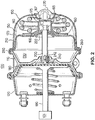
- Figure 2 is a cross-section view of a spring-type brake actuator 100 in accordance with a first embodiment of the present invention.
- the actuator housing comprises an intermediate flange 110, front cylinder 120 at a vehicle brake end of spring brake actuator 100, and rear cylinder 130 on the opposite side of intermediate flange 110.
- the terms “front” and “rear” as used herein describe the directions facing toward and facing away, respectively, a vehicle brake to which the actuator 100 is to be mounted. Thus, in Fig. 2 , “front” is the direction toward the left side of the figure, and “rear” is the direction toward the right side of the figure.
- the operating elements of spring brake actuator 100 include a brake actuator spring 140, which has one end resting on an inside rear face of spring housing 150, and an opposite end resting on a rear-facing side of a parking brake release piston 170.
- a brake actuator spring 140 which has one end resting on an inside rear face of spring housing 150, and an opposite end resting on a rear-facing side of a parking brake release piston 170.
- the present invention is not limited to a coil spring, but includes any member which provides the energy storage and return function required by a parking brake actuator.
- alternative spring configurations including multiple coil springs, leaf springs, cantilevered springs, etc., and alternative elements such as resilient blocks or chargeable high pressure bladders, are within the scope of the present invention.
- spring brake actuator 100 Also included in spring brake actuator 100 are service brake actuator 180, brake actuator rod 190 and parking brake application rod 200.
- the spring brake actuator 100 is mounted on schematically-illustrated vehicle axle and brake unit 101, with brake actuator rod 190 connected to an operating member of the brake (which may be, for example, a drum brake or disk brake).
- the parking brake release piston 170 in this embodiment comprises a diaphragm 210 captured between a supporting backing plate 220 within the rear chamber (the chamber being formed when spring housing 150 is mated to intermediate flange 110) and stamped parking brake piston 160.
- the backing plate 220 and stamped piston 170 are joined by a joining member, in this embodiment a press-fit threaded bore section 165, under a spring seat cap 175.
- the spring seat cap has a height which assists in controlling the depth of retraction of the parking brake release piston 170 when the piston 160 is manually retracted.
- a travel limiting member in this embodiment a disk-shaped plate 240 secured by fastener 242.
- the travel limiting member may have any configuration (round, square, oval, etc.), and specifically need not be a plate member, as long as (whatever its shape) it abuts the intermediate flange 110 and transfers pressure loads from the parking brake release piston 170 to the intermediate flange 110 when the parking brake release piston 170 reaches the fully-retracted position, and as long as the travel limiting member can transfer parking brake actuation force from the parking brake application rod 200 to the service brake actuator 180 to cause brake actuator rod 190 to actuate the brake.
- the spring housing 150 of rear cylinder 130 is a lightweight aluminum cap whose bead flange 250 cooperates with a corresponding bead of intermediate flange 110 to capture an outer rim 260 of rear diaphragm 210 therebetween.
- the bead flange 250 here has simply been rolled over and crimped to secure the spring housing 150 to intermediate flange 110.
- a joint such as a clamping ring, may be provided if the capability to remove the spring housing 150 in the field is desired, for example to enable replacement of a diaphragm or an internal seal.
- Parking brake release piston 170 is shown in Fig. 2 in the fully withdrawn position at the rear of parking brake release chamber 230. This position is achieved when sufficient pneumatic pressure to overcome the spring force developed by brake actuating spring 140 has been supplied, via a supply port (not illustrated), to the portion of release chamber 230 between the diaphragm 210 and the rear side of intermediate flange 110.
- the portion of the chamber on the opposite side of diaphragm 210 is sealed in this embodiment by an elastomeric plug 270 which prevents intrusion of environmental contaminants during normal operation of the brake actuator, while still allowing any excess pressure in the power spring chamber to be vented outward to atmosphere.
- the plug 270 is removable to permit insertion of a manual parking brake actuator retraction tool (not illustrated) for manual withdrawal of the parking brake piston to the parking brake release position for service.
- FIG. 2 cross-section view of the parking brake release piston 170, the capture of diaphragm 210 between the stamped parking brake piston 160 and backing plate 220 is shown, wherein the stamped parking brake piston 160 is held in position by a flange 166 of press-fit threaded bore section 165, and by the affixing of the backing plate 220 to the press-fit threaded bore section 165.
- the backing plate 220 may be affixed by any of several methods well known to those of ordinary skill in the art, including by press-fitting, spot welding or use of threaded portions on these components.
- the opposite end of the press-fit threaded bore section 165 includes a threaded section 167 which receives the manual parking brake actuator retraction tool.
- the breather valve section 165 is covered by the spring seat cap 175, which, as shown in Fig. 3 , receives one end of the power spring 140 in the region adjacent to the flange overlap 168 between the spring seat cap 175 and the stamped parking brake release piston 160.
- the thicknesses of the material of the spring seat cap 175 and the stamped parking brake release piston 160 in the flange overlap region 168 provide sufficient material thickness to support the localized high axial forces generated by the from the brake-side end of the power spring 140. For example, for a given spring strength, an thickness of 0.090-0.150 inches may be sufficient to support the spring load, where individual plates of one-half that thickness likely would not be able to sustain the spring load, at least not over the expected service life of a spring brake actuator.
- the disk-shaped plate 240 on the end of the parking brake application rod 200 ultimately limits the travel of the parking brake release piston 170, thereby serving to limiting the amount the spring 140 and the air in the power spring chamber are compressed, as well as performing its function of distributing the force generated by excess pressure in the parking brake release chamber 230 through the intermediate flange 110, rather than through housing 150.
- the travel of the parking brake release piston may be alternatively limited, for example by arranging the height of the spring seat cap 175 to correspond to the desired travel limit when the top of the cap reaches a stop surface at the rear of the spring housing 150.
Description
- The present invention relates to a spring-type brake actuator for the braking system for a vehicle, and in particular to a piston configuration for such an actuator.
- It is well known to employ so-called "spring brake" actuators to provide service, parking and emergency brake operation on vehicles such as commercial trucks, tractors and trailers equipped with lever-operated drum or disc brakes. Spring-type brake actuators are typically pneumatically operated, and are supplied with operating air from a compressed air source on the vehicle. These actuators also typically are arranged in a "fail-safe" manner, i.e., where the actuator defaults to a brake application state upon loss of operating air pressure.
- An example prior art spring brake actuator is shown in cross-section view in
Fig. 1 .Actuator housing 1 includes a rear cylinder 2 in which a rear piston 3 is displaceably arranged. The inner wall of the rear cylinder and a chamber-side of the rear piston define a rear ventilation chamber 4. The other side of the rear piston bears on abrake actuator spring 5. This spring is also known in the art as a "power spring" or a "parking brake spring," and these terms may be used interchangeably. - The rear ventilation chamber is isolated from the spring side of piston 3 by an annular seal 6. An intermediate flange 8 (also known as a "wall") separates rear cylinder 2 from a
front cylinder 9. Theintermediate flange 8 traversed by a seal 10 through which passes a parking brake application rod 11, formed as an extension of rear piston 3. The parking brake application rod 11 can be displaced in theintermediate flange 8 by the rear piston. Afront ventilation chamber 7 withinfront cylinder 9 is delimited by the cylinder inner wall and a front piston 13 andannular diaphragm 14. The rear piston 3 and the front piston 13 are in non-coupled contact with one another by means of the parking brake application rod 11, such that the front piston 13 can be displaced in a brake application direction by the rear piston 3 and/or by the application of pneumatic pressure infront ventilation chamber 7. An actuatingrod 15 for actuating a brake lever of a vehicle brake is provided on the front side of the front piston 13. -
Fig. 1 also showsmounting studs 16 provided for mounting of theactuator 1 on the vehicle brake, as well as alight return spring 18 which biases front piston 13 toward the rear offront chamber 7. - When no pneumatic pressure is present in the
Fig. 1 actuator unit, thebrake actuation spring 5 applies a high spring force to rear piston 3, which in turn applies this force via parking brake application rod 11 to front piston 13 to cause theactuator rod 15 to apply the vehicle brake. In this state, the vehicle brake functions as a parking brake, preventing vehicle movement. - When release of the parking brake is desired, the rear ventilation chamber 4 is filled with compressed air via a ventilation port (not illustrated). As the force generated by the increasing air pressure on the front side of rear piston 3 exceeds the force generated by
brake application spring 5, the rear piston 3 and parking brake application rod 11 move toward the rear of the rear cylinder 2, compressingspring 5 and causing air in the rear of rear cylinder 2 to be vented to atmosphere through passages in rear piston 3 (not illustrated) to ventpath 19. - As parking brake application rod 11 moves towards the rear, the force previously applied to front piston 13 is relieved, and the
return spring 18 biases the front piston 13 toward the rear offront cylinder 9, thereby withdrawing actuatingrod 15 away from and releasing the vehicle brake. The vehicle therefore moves from a state in which it is braked by thebrake actuator spring 5, to a non-braked state in which the vehicle may be moved. The vehicle brake is applied as a service during normal operation by admitting compressed air into the front ventilation chamber 7 (via a port not shown inFig. 1 ). Because air pressure in rear ventilation chamber 4 continues to hold parking brake application rod 11 at the rear of the rear cylinder 2, the front piston 13 and actuatingrod 15 are free to move forward and backward within the front cylinder as necessary to respond to the operator's brake actuation demands. - The parking brake piston in a spring brake actuator (in the
Fig. 1 example, rear piston 3) may be a relatively complex structure, and therefore typically is formed in one piece as a cast part. The cast piston is most commonly cast from Aluminum, a material with desirable light weight and suitability for using in casting processes. - Although cast aluminum parking brake pistons are relatively low cost, they are subject to large fluctuations in cost due to large Aluminum material market price fluctuations. Moreover, the tooling used for forming cast Aluminum pistons tends to be relatively short-lived, on the order of only 100,000 casting shots before the tooling must be replaced. This short tooling life raises the cost of the case Aluminum piston parts over which the tooling costs are distributed. Cast Aluminum parking brake pistons also typically require costly machining operations to prepare their surfaces for use with rubber diaphragms, as well as for receiving parking brake release rods and finishing of ventilation features.
DocumentWO 00/30913 A1
DocumentUS 4 231 286 A andUS 2010/154227 A discloses a spring brake actuator with a cast parking brake piston as described above. - In view of the foregoing problems with current spring-type brake actuator parking brake pistons and related actuator components, the present invention provides an improved parking brake piston and spring brake actuator which, as compared to prior art cast parking brake pistons, is simpler and less costly to manufacture and assemble, reduces stresses on the actuator housing when the parking brake piston is manually withdrawn with a parking brake release tool, and allows the use of self-ventilating chambers and thus eliminate the need to have external breathing and its associated corrosion problems.
- In the present invention the previous cast aluminum parking brake piston is replaced by a stamped piston arrangement, in which a stamped disk is affixed to the parking brake actuator diaphragm, preferably with the diaphragm captured between opposing stamped plates. The use of stamping permits the use of stamping tooling which is much longer-lived than cast tooling (typically on the order of one million stampings before tooling replacement, as compared to typically on the order of 100,000 casting shots before the casting tooling must be replaced). Preferably, the stamped piston design includes a threaded insert which secures the parking brake piston to the parking brake retraction rod, a feature which on an equivalent cast aluminum parking brake piston tooling would require expensive side features to be included with the casting die. The present approach thus provides an economical way to provide for manual retraction of the parking brake actuator in a manner already familiar to vehicle operators and technicians. The threaded insert may be formed or attached to the stamped piston in a variety of ways, for example, by spot-welding to the stamped piston. Further, a pressed-in threaded insert may be used with the stampings, as such an insert permits the use of a larger diameter breather valve arrangement than in a cast parking brake piston.
- In a preferred embodiment, the stamped piston is paired with a spring seat cap element, also preferably formed by stamping, which abuts the stamped piston on the power spring side of the piston. The spring seat cap element further may be arranged to receive the brake-side end of the power spring, such that the force of the spring is borne by the spring seat cap element instead of being directly applied to the stamped piston plate. This configuration permits the use of a stamped piston plate and a spring seat cap element with thicknesses which are individually insufficient to sustain the axial force generated by the power spring, but when combined are sufficient to successfully manage the force of the power spring as a result of the effective doubling of the thickness of these stamped components in the region of the brake-side end of the power spring. This permits the use of unexpectedly thin, less costly parking brake release piston components (less costly in terms of both material costs and production costs (e.g., lower tooling costs due to use of thinner material sheets which do not require high-force stamping presses and which do not wear tooling as quickly as thicker materials), while still providing sufficient strength to bear the loads applied to the parking brake release piston by the power spring.
- Because no significant tension loads must be carried through the spring seat cap element and the stamped piston plate, there is no need to provide a strong bonding between these components, such as a full circumferential weld of the cap to the piston. As a result, costly and time consuming high tensile strength joining methods, such as full peripheral welding, riveting, or use of fasteners may be eliminated. In some applications, it may be desirable to lightly spot-weld the spring seat cap element to the stamped piston to aid actuator assembly by ensuring concentric arrangements of these components. Alternatively, because these components are only loaded in compression relative to one another, in some applications the fixing of the spring seat cap element to the stamped piston plate may be dispensed with altogether. It is further advantageous if the spring seat cap element has a generally conical shape above the stamped piston, an arrangement which provides for greater resistance against deformation in tension or compression than a cylindrically-configured cap element (for example, when a manual brake retraction tool pulls on the cap element, or when the top of the cap element serves as a piston travel stop against the rear of the power spring chamber).
- The design also may include a diaphragm-to-rod sealing element and an internal breathing arrangement within the stamped parking brake piston center arrangements to permit chamber breathing, eliminating any need to allow outside environmental air to enter the power spring portion of the spring housing and thereby eliminating the potential for contaminant entry into the brake actuator housing. A stamped spring seat cap element also provides for a larger internal volume under the cap for elements such as breather valves than was typically available in prior art cast parking brake release piston designs.
- In a further embodiment, the parking brake retraction rod passes through an intermediate flange of the brake actuator, and has a plate or equivalent structure affixed to the end of the rod on the side of the intermediate flange opposite the parking brake actuator. With such an arrangement, once sufficient pressure is present to fully retract the parking brake piston to the point that the plate at the end of the rod abuts the intermediate flange of the actuator housing, (for example, at approximately 70-75 psi), any further increases in pressure (for example, an increase to a system pressure of 135 psi) results in the additional pressure load advantageously being carried by the intermediate flange, rather than the parking brake section's portion of the housing (also known as the spring housing) as is typical with prior art conventional brake actuators, whose parking brake pistons apply all of their axial loads through the compressed power spring to the end of the housing. Thus, the present invention permits design of the parking brake housing portion of the actuator to significantly lower stress levels, enabling further weight and cost reductions as compared to prior art actuators.
- The material used for the stamped piston may be a naturally corrosion-resistant material such as aluminum, or may be a material such as steel to which a corrosion-inhibiting coating is applied. In view of the decreased exposure to external environmental contaminants in the present invention, additional corrosion-inhibiting coatings may be dispensed with altogether.
- Other objects, advantages and novel features of the present invention will become apparent from the following detailed description of the invention when considered in conjunction with the accompanying drawings.
-
-
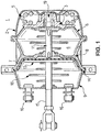
Figure 1 is a cross-section view of an example of a previously known spring-type pneumatic brake actuator. -
Figure 2 is a cross-section view of an embodiment of a spring-type brake actuator in accordance with the present invention. -
Figure 3 is a cross-section view of a stamped parking brake piston arrangement such as that shown inFig. 2 . -
Figure 2 is a cross-section view of a spring-type brake actuator 100 in accordance with a first embodiment of the present invention. - The actuator housing comprises an
intermediate flange 110,front cylinder 120 at a vehicle brake end ofspring brake actuator 100, andrear cylinder 130 on the opposite side ofintermediate flange 110. The terms "front" and "rear" as used herein describe the directions facing toward and facing away, respectively, a vehicle brake to which theactuator 100 is to be mounted. Thus, inFig. 2 , "front" is the direction toward the left side of the figure, and "rear" is the direction toward the right side of the figure. - The operating elements of
spring brake actuator 100 include abrake actuator spring 140, which has one end resting on an inside rear face ofspring housing 150, and an opposite end resting on a rear-facing side of a parkingbrake release piston 170. It is to be understood that the present invention is not limited to a coil spring, but includes any member which provides the energy storage and return function required by a parking brake actuator. For example, alternative spring configurations, including multiple coil springs, leaf springs, cantilevered springs, etc., and alternative elements such as resilient blocks or chargeable high pressure bladders, are within the scope of the present invention. - Also included in
spring brake actuator 100 areservice brake actuator 180,brake actuator rod 190 and parkingbrake application rod 200. Thespring brake actuator 100 is mounted on schematically-illustrated vehicle axle andbrake unit 101, withbrake actuator rod 190 connected to an operating member of the brake (which may be, for example, a drum brake or disk brake). - The parking
brake release piston 170 in this embodiment comprises adiaphragm 210 captured between a supportingbacking plate 220 within the rear chamber (the chamber being formed whenspring housing 150 is mated to intermediate flange 110) and stampedparking brake piston 160. In this embodiment, thebacking plate 220 and stampedpiston 170 are joined by a joining member, in this embodiment a press-fit threadedbore section 165, under aspring seat cap 175. In this example, the spring seat cap has a height which assists in controlling the depth of retraction of the parkingbrake release piston 170 when thepiston 160 is manually retracted. - As the brake end of parking
brake application rod 200 is affixed a travel limiting member, in this embodiment a disk-shaped plate 240 secured byfastener 242. The travel limiting member may have any configuration (round, square, oval, etc.), and specifically need not be a plate member, as long as (whatever its shape) it abuts theintermediate flange 110 and transfers pressure loads from the parkingbrake release piston 170 to theintermediate flange 110 when the parkingbrake release piston 170 reaches the fully-retracted position, and as long as the travel limiting member can transfer parking brake actuation force from the parkingbrake application rod 200 to theservice brake actuator 180 to causebrake actuator rod 190 to actuate the brake. - In this embodiment, the
spring housing 150 ofrear cylinder 130 is a lightweight aluminum cap whosebead flange 250 cooperates with a corresponding bead ofintermediate flange 110 to capture anouter rim 260 ofrear diaphragm 210 therebetween. In order to minimize manufacturing and material costs, thebead flange 250 here has simply been rolled over and crimped to secure thespring housing 150 tointermediate flange 110. Alternatively, a joint, such as a clamping ring, may be provided if the capability to remove thespring housing 150 in the field is desired, for example to enable replacement of a diaphragm or an internal seal. - Parking
brake release piston 170 is shown inFig. 2 in the fully withdrawn position at the rear of parkingbrake release chamber 230. This position is achieved when sufficient pneumatic pressure to overcome the spring force developed bybrake actuating spring 140 has been supplied, via a supply port (not illustrated), to the portion ofrelease chamber 230 between thediaphragm 210 and the rear side ofintermediate flange 110. The portion of the chamber on the opposite side ofdiaphragm 210, is sealed in this embodiment by anelastomeric plug 270 which prevents intrusion of environmental contaminants during normal operation of the brake actuator, while still allowing any excess pressure in the power spring chamber to be vented outward to atmosphere. Theplug 270 is removable to permit insertion of a manual parking brake actuator retraction tool (not illustrated) for manual withdrawal of the parking brake piston to the parking brake release position for service. - In the
Fig. 2 cross-section view of the parkingbrake release piston 170, the capture ofdiaphragm 210 between the stampedparking brake piston 160 andbacking plate 220 is shown, wherein the stampedparking brake piston 160 is held in position by aflange 166 of press-fit threadedbore section 165, and by the affixing of thebacking plate 220 to the press-fit threadedbore section 165. Thebacking plate 220 may be affixed by any of several methods well known to those of ordinary skill in the art, including by press-fitting, spot welding or use of threaded portions on these components. The opposite end of the press-fit threadedbore section 165 includes a threadedsection 167 which receives the manual parking brake actuator retraction tool. - The
breather valve section 165 is covered by thespring seat cap 175, which, as shown inFig. 3 , receives one end of thepower spring 140 in the region adjacent to theflange overlap 168 between thespring seat cap 175 and the stamped parkingbrake release piston 160. The thicknesses of the material of thespring seat cap 175 and the stamped parkingbrake release piston 160 in theflange overlap region 168 provide sufficient material thickness to support the localized high axial forces generated by the from the brake-side end of thepower spring 140. For example, for a given spring strength, an thickness of 0.090-0.150 inches may be sufficient to support the spring load, where individual plates of one-half that thickness likely would not be able to sustain the spring load, at least not over the expected service life of a spring brake actuator. - During operation of the
spring brake actuator 100, air is admitted to parkingbrake release chamber 230 to cause the parkingbrake release piston 170 to move toward the rear of theparking brake housing 150, thereby compressing thepower spring 140 and permitting thebrake actuator rod 190 to be withdrawn to release the brake. As the parkingbrake release piston 170 moves toward the rear of thespring housing 150, the air within the power spring chamber is compressed, and may be vented to atmosphere via port in the power spring chamber (not illustrated). As shown inFig. 2 , the disk-shaped plate 240 on the end of the parkingbrake application rod 200 ultimately limits the travel of the parkingbrake release piston 170, thereby serving to limiting the amount thespring 140 and the air in the power spring chamber are compressed, as well as performing its function of distributing the force generated by excess pressure in the parkingbrake release chamber 230 through theintermediate flange 110, rather than throughhousing 150. The travel of the parking brake release piston may be alternatively limited, for example by arranging the height of thespring seat cap 175 to correspond to the desired travel limit when the top of the cap reaches a stop surface at the rear of thespring housing 150. - The foregoing disclosure has been set forth merely to illustrate the invention and is not intended to be limiting. Because other such modifications of the disclosed embodiments incorporating the substance of the invention may occur to persons skilled in the art, the invention should be construed to include everything within the scope of the appended claims.
Claims (7)
- A spring brake actuator (100), comprising:an actuator intermediate flange member (110);a spring housing (150) configured to be affixed to a first side of the actuator intermediate flange member (110) to form a parking brake actuator chamber;a service brake housing (120) configured to be affixed to a second side of the actuator intermediate flange member (110) opposite the first side;a parking brake release piston (170) comprising a stamped piston plate (160) and a flexible diaphragm (210), the parking brake release piston (170) being configured to divide the parking brake actuator chamber into a parking brake release chamber (230) on an intermediate flange side of the parking brake release piston and a power spring chamber (130) on an opposite side of the parking brake release piston (170);a parking brake actuating power spring (140) arranged in the power spring chamber (130) to bias the parking brake release piston (170) away from a rear wall portion of the spring housing (150); characterized in that the spring brake actuator further comprisesa spring seat cap (175) having at least a flange region arranged to transfer power spring biasing force between the power spring (140) and the parking brake release piston plate (160) in a region of an inner radius of the power spring (140), the spring seat cap (175) having an axially-extending cap portion located within the inner radius of the power spring (140) and extending from the flange region toward the spring housing rear wall portion (150); anda parking brake release operating rod (200) affixed at a first rod end to the parking brake release piston (170) and at a second rod end to a travel limiting member (240) in the service brake actuator chamber (230), the operating rod (200) having a rod length such that the travel limiting member (240) abuts the second side of the intermediate flange (110) before the spring cap (175) contacts the spring housing (150) when the parking brake release piston (175) is located at a fully withdrawn position.
- The spring brake actuator of claim 1, wherein
the spring seat cap (175) is formed from a stamped plate. - The spring brake actuator of claim 1, further comprising:a backing member (220) affixed to the parking brake release operating rod (200),wherein the flexible diaphragm (210) is located between the stamped piston plate (160) and the backing member (220).
- A vehicle brake assembly, comprising:a brake, wherein the brake includes one of a disc brake and a drum brake; anda spring brake actuator (100) coupled to the brake to apply a brake actuation force, the spring brake actuator (100) includingan actuator intermediate flange member (110);a spring housing (150) configured to be affixed to a first side of the actuator intermediate flange member (110) to form a parking brake actuator chamber;a service brake housing (120) configured to be affixed to a second side of the actuator intermediate flange member (110) opposite the first side;a parking brake release piston (170) comprising a stamped piston plate (160) and a flexible diaphragm (210), the parking brake release piston (170) being configured to divide the parking brake actuator chamber into a parking brake release chamber (230) on an intermediate flange side of the parking brake release piston (170) and a power spring chamber (130) on an opposite side of the parking brake release piston (170);a parking brake actuating power spring (140) arranged in the power spring chamber (130) to bias the parking brake release piston (170) away from a rear wall portion of the spring housing (150);characterized in that the spring brake actuator further comprisesa spring seat cap (175) having at least a flange region arranged to transfer power spring biasing force between the power spring (140) and the parking brake release piston plate (160) in a region of an inner radius of the power spring (140), the spring seat cap (175) having an axially-extending cap portion located within the inner radius of the power spring (140) and extending from the flange region toward the spring housing rear wall portion (150); and
a parking brake release operating rod (200) affixed at a first rod end to the parking brake release piston (170) and at a second rod end to a travel limiting member (240) in the service brake actuator chamber (230), the operating rod (200) having a rod length such that the travel limiting member (240) abuts the second side of the intermediate flange (110) before the spring cap (175) contacts the spring housing (150) when the parking brake release piston (175) is located at a fully withdrawn position. - The vehicle brake assembly of claim 5, wherein
the spring seat cap (175) is formed from a stamped plate. - The vehicle brake assembly of claim 6, further comprising:a backing member (220) affixed to the parking brake release operating rod (200),wherein the flexible diaphragm (210) is located between the stamped piston plate (160) and the backing member (220).
- A method of operating a spring brake actuator (100), comprising the acts of:providing a spring brake actuator, the spring brake actuator comprising:an actuator intermediate flange member (110);a spring housing (150)configured to be affixed to a first side of the actuator intermediate flange member (110) to form a parking brake actuator chamber;a service brake housing (120) configured to be affixed to a second side of the actuator intermediate flange member (110) opposite the first side;a parking brake release piston (170) comprising a stamped piston plate (160) and a flexible diaphragm (210), the parking brake release piston (170) being configured to divide the parking brake actuator chamber into a parking brake release chamber (230) on an intermediate flange side of the parking brake release piston (170) and a power spring chamber (130) on an opposite side of the parking brake release piston (170);a parking brake actuating power spring (140) arranged in the power spring chamber (130) to bias the parking brake release piston (170) away from a rear wall portion of the spring housing (150); characterized in that the spring brake actuator further comprisesa spring seat cap (175) having at least a flange region arranged to transfer power spring biasing force between the power spring (140) and the parking brake release piston plate (160) in a region of an inner radius of the power spring (140), the spring seat cap (175) having an axially-extending cap portion located within the inner radius of the power spring (140) and extending from the flange region toward the spring housing rear wall portion (150); and
a parking brake release operating rod (200) affixed at a first rod end to the parking brake release piston (170) and at a second rod end to a travel limiting member (240) in the service brake actuator chamber (230), the operating rod (200) having a rod length such that the travel limiting member (240) abuts the second side of the intermediate flange (110) before the spring cap (175) contacts the spring housing (150) when the parking brake release piston (175) is located at a fully withdrawn position;applying fluidic pressure to the parking brake release chamber (230) to cause the parking brake release piston (170) to compress the power spring (140);releasing the fluidic pressure in the parking brake release chamber (230) to cause the power spring (140) to displace the parking brake release piston (170) away from the rear wall portion of the spring housing (150).
Applications Claiming Priority (2)
| Application Number | Priority Date | Filing Date | Title |
|---|---|---|---|
| US13/247,449 US9004236B2 (en) | 2011-09-28 | 2011-09-28 | Parking brake piston for a parking brake chamber |
| PCT/US2012/051058 WO2013048632A1 (en) | 2011-09-28 | 2012-08-16 | Parking brake piston for a parking brake chamber |
Publications (3)
| Publication Number | Publication Date |
|---|---|
| EP2760720A1 EP2760720A1 (en) | 2014-08-06 |
| EP2760720A4 EP2760720A4 (en) | 2015-04-15 |
| EP2760720B1 true EP2760720B1 (en) | 2018-10-10 |
Family
ID=47910028
Family Applications (1)
| Application Number | Title | Priority Date | Filing Date |
|---|---|---|---|
| EP12835604.5A Not-in-force EP2760720B1 (en) | 2011-09-28 | 2012-08-16 | Parking brake piston for a parking brake chamber |
Country Status (4)
| Country | Link |
|---|---|
| US (1) | US9004236B2 (en) |
| EP (1) | EP2760720B1 (en) |
| CN (1) | CN103958302B (en) |
| WO (1) | WO2013048632A1 (en) |
Families Citing this family (12)
| Publication number | Priority date | Publication date | Assignee | Title |
|---|---|---|---|---|
| WO2014126367A1 (en) * | 2013-02-12 | 2014-08-21 | (주)지앤피오토모티브 | Apparatus for coupling diaphragm for center hole of brake chamber for vehicle |
| DE102013110639B4 (en) * | 2013-09-26 | 2020-08-06 | Knorr-Bremse Systeme für Nutzfahrzeuge GmbH | Method for producing a positive connection between at least one housing of a service brake cylinder of a combined service brake and spring-loaded brake cylinder consisting of a deformable material |
| CN104071140A (en) * | 2014-06-25 | 2014-10-01 | 嘉兴盛鼎机械有限公司 | Light weight all aluminum brake air chamber and preparation method thereof |
| US9701294B2 (en) | 2015-08-25 | 2017-07-11 | Bendix Spicer Foundation Brake Llc | Pull style double diaphragm spring brake actuator |
| US9745874B2 (en) | 2015-10-21 | 2017-08-29 | Schaeffler Technologies AG & Co. KG | Piston assembly retainer with integrated spring seat |
| CN106080545B (en) * | 2016-07-29 | 2019-01-18 | 安徽工程大学 | Brake system of car |
| US11752993B2 (en) * | 2019-04-08 | 2023-09-12 | Zf Cv Systems Europe Bv | Spring brake, brake system, and motor vehicle |
| CN113784879A (en) * | 2019-05-16 | 2021-12-10 | 采埃孚商用车系统欧洲有限公司 | Piston tube assembly for a spring brake actuator and spring brake actuator |
| DE102020112751A1 (en) * | 2020-05-12 | 2021-11-18 | Dr. Ing. H.C. F. Porsche Aktiengesellschaft | Motor vehicle with a braking device |
| US11866016B2 (en) | 2020-09-10 | 2024-01-09 | Industrial Machine Service, Inc. | Gas-liquid separating gas exchange device |
| US11745710B2 (en) * | 2020-12-18 | 2023-09-05 | Zf Commercial Vehicle Control Systems India Limited | Spring brake actuator for use in a commercial vehicle and commercial vehicle therewith |
| US20230365112A1 (en) * | 2022-05-10 | 2023-11-16 | Zf Commercial Vehicle Control Systems India Limited | Brake actuator for a vehicle including a cylinder and dust plug |
Family Cites Families (17)
| Publication number | Priority date | Publication date | Assignee | Title |
|---|---|---|---|---|
| US2977935A (en) * | 1958-09-10 | 1961-04-04 | Glenn T Randol | Pressure differential operated brake booster mechanism |
| US3152524A (en) | 1962-08-31 | 1964-10-13 | Westinghouse Air Brake Co | Brake cylinder |
| US3508469A (en) * | 1968-10-29 | 1970-04-28 | Rockwell Standard Co | Multiple balanced spring brake actuator |
| US3712181A (en) * | 1968-12-09 | 1973-01-23 | Certain Teed Prod Corp | Internal air assisted brake actuator |
| US3811365A (en) * | 1971-09-13 | 1974-05-21 | Indian Head Inc | Brake mechanism |
| US4231286A (en) * | 1979-06-13 | 1980-11-04 | The Echlin Manufacturing Company | Brake actuators |
| US4263840A (en) * | 1979-10-29 | 1981-04-28 | Stratobrake Corporation | Safety brake mechanism |
| US4960036A (en) * | 1987-11-06 | 1990-10-02 | Indian Head Industries, Inc. | Tamper-resistant brake actuator |
| US5014599A (en) | 1990-02-26 | 1991-05-14 | Federal-Mogul Corporation | Two piece hydraulic piston assembly with swaged piston-sleeve joint |
| US5791232A (en) * | 1995-07-26 | 1998-08-11 | Tse Brakes, Inc. | Universal adapter pressure cap |
| US5836233A (en) * | 1997-03-07 | 1998-11-17 | Rumsey; Donald | Spring brake with sealable breather holes |
| WO2000030913A1 (en) * | 1998-11-24 | 2000-06-02 | Holland Neway International, Inc. | Two-piece pressure plate and method of fabrication |
| US6289786B1 (en) | 2000-03-22 | 2001-09-18 | Indian Head Industries Inc. | Brake actuator having an improved piston and method of making same |
| US7343847B2 (en) | 2005-07-22 | 2008-03-18 | Bendix Spicer Foundation Brake Llc | Actuator for a brake system and method of making a brake actuator |
| US7121191B1 (en) * | 2005-09-01 | 2006-10-17 | Haldex Brake Corporation | Air-operated brake actuator with control valve |
| CN101144795B (en) | 2007-10-29 | 2010-06-02 | 钢铁研究总院 | Impulse melting-flying time mass spectrometry for element |
| US8342076B2 (en) * | 2008-12-22 | 2013-01-01 | Indian Head Industries, Inc. | Brake actuator and method of forming the same |
-
2011
- 2011-09-28 US US13/247,449 patent/US9004236B2/en active Active
-
2012
- 2012-08-16 CN CN201280057854.2A patent/CN103958302B/en active Active
- 2012-08-16 EP EP12835604.5A patent/EP2760720B1/en not_active Not-in-force
- 2012-08-16 WO PCT/US2012/051058 patent/WO2013048632A1/en active Application Filing
Non-Patent Citations (1)
| Title |
|---|
| None * |
Also Published As
| Publication number | Publication date |
|---|---|
| EP2760720A4 (en) | 2015-04-15 |
| WO2013048632A1 (en) | 2013-04-04 |
| CN103958302B (en) | 2016-12-14 |
| CN103958302A (en) | 2014-07-30 |
| EP2760720A1 (en) | 2014-08-06 |
| US20130075211A1 (en) | 2013-03-28 |
| US9004236B2 (en) | 2015-04-14 |
Similar Documents
| Publication | Publication Date | Title |
|---|---|---|
| EP2760720B1 (en) | Parking brake piston for a parking brake chamber | |
| EP0575830B1 (en) | Tamper-resistant brake actuator | |
| CA2850123C (en) | Parking piston direct connection to apr rod | |
| EP2674640B1 (en) | Deflection spring pneumatic actuator | |
| US5105727A (en) | Spring brake actuator with an annular edge of a diaphragm sealed between a tubular part of a pressure plate and an actuator rod | |
| EP0433571B1 (en) | Adjustable mounting apparatus for air-operated diaphragm brakes | |
| CN108944892B (en) | Spring brake actuator with lock bolt bearing connecting pressure plate and actuator tube | |
| EP2760719B1 (en) | Parking brake chamber internal breathing system | |
| CA2733689C (en) | Non-threaded method for assembling a center hole parking diaphragm and adapter push rod with a clip and washer | |
| US8127903B2 (en) | Integral light weight spring brake actuator and mount | |
| WO1994021931A1 (en) | Spring brake actuator and caging bolt therefor | |
| US20120006192A1 (en) | Adhesive Attachment Of The Disc Brake Pushrod Plate To The Diaphragm | |
| JP2003508297A (en) | Brake booster with wall mounting means | |
| US9701294B2 (en) | Pull style double diaphragm spring brake actuator | |
| US20070063580A1 (en) | Concentric series power springs located in the middle of the spring brake actuator | |
| US7743894B2 (en) | Brake actuator reinforcement and method of attaching same | |
| US20070039787A1 (en) | Static/dynamic pressure-energized seal for a brake actuator | |
| EP1192071B1 (en) | Service brake actuator having a unitary pushrod assembly with a bushing therefor |
Legal Events
| Date | Code | Title | Description |
|---|---|---|---|
| PUAI | Public reference made under article 153(3) epc to a published international application that has entered the european phase |
Free format text: ORIGINAL CODE: 0009012 |
|
| 17P | Request for examination filed |
Effective date: 20140428 |
|
| AK | Designated contracting states |
Kind code of ref document: A1 Designated state(s): AL AT BE BG CH CY CZ DE DK EE ES FI FR GB GR HR HU IE IS IT LI LT LU LV MC MK MT NL NO PL PT RO RS SE SI SK SM TR |
|
| DAX | Request for extension of the european patent (deleted) | ||
| RA4 | Supplementary search report drawn up and despatched (corrected) |
Effective date: 20150318 |
|
| RIC1 | Information provided on ipc code assigned before grant |
Ipc: B60T 17/08 20060101AFI20150312BHEP |
|
| GRAP | Despatch of communication of intention to grant a patent |
Free format text: ORIGINAL CODE: EPIDOSNIGR1 |
|
| STAA | Information on the status of an ep patent application or granted ep patent |
Free format text: STATUS: GRANT OF PATENT IS INTENDED |
|
| INTG | Intention to grant announced |
Effective date: 20180508 |
|
| GRAS | Grant fee paid |
Free format text: ORIGINAL CODE: EPIDOSNIGR3 |
|
| GRAA | (expected) grant |
Free format text: ORIGINAL CODE: 0009210 |
|
| STAA | Information on the status of an ep patent application or granted ep patent |
Free format text: STATUS: THE PATENT HAS BEEN GRANTED |
|
| AK | Designated contracting states |
Kind code of ref document: B1 Designated state(s): AL AT BE BG CH CY CZ DE DK EE ES FI FR GB GR HR HU IE IS IT LI LT LU LV MC MK MT NL NO PL PT RO RS SE SI SK SM TR |
|
| REG | Reference to a national code |
Ref country code: GB Ref legal event code: FG4D |
|
| REG | Reference to a national code |
Ref country code: CH Ref legal event code: EP Ref country code: AT Ref legal event code: REF Ref document number: 1050865 Country of ref document: AT Kind code of ref document: T Effective date: 20181015 |
|
| REG | Reference to a national code |
Ref country code: IE Ref legal event code: FG4D |
|
| REG | Reference to a national code |
Ref country code: DE Ref legal event code: R096 Ref document number: 602012052145 Country of ref document: DE |
|
| REG | Reference to a national code |
Ref country code: NL Ref legal event code: MP Effective date: 20181010 |
|
| REG | Reference to a national code |
Ref country code: LT Ref legal event code: MG4D |
|
| REG | Reference to a national code |
Ref country code: AT Ref legal event code: MK05 Ref document number: 1050865 Country of ref document: AT Kind code of ref document: T Effective date: 20181010 |
|
| PG25 | Lapsed in a contracting state [announced via postgrant information from national office to epo] |
Ref country code: NL Free format text: LAPSE BECAUSE OF FAILURE TO SUBMIT A TRANSLATION OF THE DESCRIPTION OR TO PAY THE FEE WITHIN THE PRESCRIBED TIME-LIMIT Effective date: 20181010 |
|
| PG25 | Lapsed in a contracting state [announced via postgrant information from national office to epo] |
Ref country code: ES Free format text: LAPSE BECAUSE OF FAILURE TO SUBMIT A TRANSLATION OF THE DESCRIPTION OR TO PAY THE FEE WITHIN THE PRESCRIBED TIME-LIMIT Effective date: 20181010 Ref country code: IS Free format text: LAPSE BECAUSE OF FAILURE TO SUBMIT A TRANSLATION OF THE DESCRIPTION OR TO PAY THE FEE WITHIN THE PRESCRIBED TIME-LIMIT Effective date: 20190210 Ref country code: AT Free format text: LAPSE BECAUSE OF FAILURE TO SUBMIT A TRANSLATION OF THE DESCRIPTION OR TO PAY THE FEE WITHIN THE PRESCRIBED TIME-LIMIT Effective date: 20181010 Ref country code: LT Free format text: LAPSE BECAUSE OF FAILURE TO SUBMIT A TRANSLATION OF THE DESCRIPTION OR TO PAY THE FEE WITHIN THE PRESCRIBED TIME-LIMIT Effective date: 20181010 Ref country code: PL Free format text: LAPSE BECAUSE OF FAILURE TO SUBMIT A TRANSLATION OF THE DESCRIPTION OR TO PAY THE FEE WITHIN THE PRESCRIBED TIME-LIMIT Effective date: 20181010 Ref country code: NO Free format text: LAPSE BECAUSE OF FAILURE TO SUBMIT A TRANSLATION OF THE DESCRIPTION OR TO PAY THE FEE WITHIN THE PRESCRIBED TIME-LIMIT Effective date: 20190110 Ref country code: BG Free format text: LAPSE BECAUSE OF FAILURE TO SUBMIT A TRANSLATION OF THE DESCRIPTION OR TO PAY THE FEE WITHIN THE PRESCRIBED TIME-LIMIT Effective date: 20190110 Ref country code: FI Free format text: LAPSE BECAUSE OF FAILURE TO SUBMIT A TRANSLATION OF THE DESCRIPTION OR TO PAY THE FEE WITHIN THE PRESCRIBED TIME-LIMIT Effective date: 20181010 Ref country code: LV Free format text: LAPSE BECAUSE OF FAILURE TO SUBMIT A TRANSLATION OF THE DESCRIPTION OR TO PAY THE FEE WITHIN THE PRESCRIBED TIME-LIMIT Effective date: 20181010 Ref country code: HR Free format text: LAPSE BECAUSE OF FAILURE TO SUBMIT A TRANSLATION OF THE DESCRIPTION OR TO PAY THE FEE WITHIN THE PRESCRIBED TIME-LIMIT Effective date: 20181010 |
|
| PG25 | Lapsed in a contracting state [announced via postgrant information from national office to epo] |
Ref country code: SE Free format text: LAPSE BECAUSE OF FAILURE TO SUBMIT A TRANSLATION OF THE DESCRIPTION OR TO PAY THE FEE WITHIN THE PRESCRIBED TIME-LIMIT Effective date: 20181010 Ref country code: AL Free format text: LAPSE BECAUSE OF FAILURE TO SUBMIT A TRANSLATION OF THE DESCRIPTION OR TO PAY THE FEE WITHIN THE PRESCRIBED TIME-LIMIT Effective date: 20181010 Ref country code: RS Free format text: LAPSE BECAUSE OF FAILURE TO SUBMIT A TRANSLATION OF THE DESCRIPTION OR TO PAY THE FEE WITHIN THE PRESCRIBED TIME-LIMIT Effective date: 20181010 Ref country code: GR Free format text: LAPSE BECAUSE OF FAILURE TO SUBMIT A TRANSLATION OF THE DESCRIPTION OR TO PAY THE FEE WITHIN THE PRESCRIBED TIME-LIMIT Effective date: 20190111 Ref country code: PT Free format text: LAPSE BECAUSE OF FAILURE TO SUBMIT A TRANSLATION OF THE DESCRIPTION OR TO PAY THE FEE WITHIN THE PRESCRIBED TIME-LIMIT Effective date: 20190210 |
|
| REG | Reference to a national code |
Ref country code: DE Ref legal event code: R097 Ref document number: 602012052145 Country of ref document: DE |
|
| PG25 | Lapsed in a contracting state [announced via postgrant information from national office to epo] |
Ref country code: CZ Free format text: LAPSE BECAUSE OF FAILURE TO SUBMIT A TRANSLATION OF THE DESCRIPTION OR TO PAY THE FEE WITHIN THE PRESCRIBED TIME-LIMIT Effective date: 20181010 Ref country code: DK Free format text: LAPSE BECAUSE OF FAILURE TO SUBMIT A TRANSLATION OF THE DESCRIPTION OR TO PAY THE FEE WITHIN THE PRESCRIBED TIME-LIMIT Effective date: 20181010 Ref country code: IT Free format text: LAPSE BECAUSE OF FAILURE TO SUBMIT A TRANSLATION OF THE DESCRIPTION OR TO PAY THE FEE WITHIN THE PRESCRIBED TIME-LIMIT Effective date: 20181010 |
|
| PLBE | No opposition filed within time limit |
Free format text: ORIGINAL CODE: 0009261 |
|
| STAA | Information on the status of an ep patent application or granted ep patent |
Free format text: STATUS: NO OPPOSITION FILED WITHIN TIME LIMIT |
|
| PG25 | Lapsed in a contracting state [announced via postgrant information from national office to epo] |
Ref country code: SM Free format text: LAPSE BECAUSE OF FAILURE TO SUBMIT A TRANSLATION OF THE DESCRIPTION OR TO PAY THE FEE WITHIN THE PRESCRIBED TIME-LIMIT Effective date: 20181010 Ref country code: RO Free format text: LAPSE BECAUSE OF FAILURE TO SUBMIT A TRANSLATION OF THE DESCRIPTION OR TO PAY THE FEE WITHIN THE PRESCRIBED TIME-LIMIT Effective date: 20181010 Ref country code: EE Free format text: LAPSE BECAUSE OF FAILURE TO SUBMIT A TRANSLATION OF THE DESCRIPTION OR TO PAY THE FEE WITHIN THE PRESCRIBED TIME-LIMIT Effective date: 20181010 Ref country code: SK Free format text: LAPSE BECAUSE OF FAILURE TO SUBMIT A TRANSLATION OF THE DESCRIPTION OR TO PAY THE FEE WITHIN THE PRESCRIBED TIME-LIMIT Effective date: 20181010 |
|
| 26N | No opposition filed |
Effective date: 20190711 |
|
| PG25 | Lapsed in a contracting state [announced via postgrant information from national office to epo] |
Ref country code: SI Free format text: LAPSE BECAUSE OF FAILURE TO SUBMIT A TRANSLATION OF THE DESCRIPTION OR TO PAY THE FEE WITHIN THE PRESCRIBED TIME-LIMIT Effective date: 20181010 |
|
| REG | Reference to a national code |
Ref country code: DE Ref legal event code: R119 Ref document number: 602012052145 Country of ref document: DE |
|
| PG25 | Lapsed in a contracting state [announced via postgrant information from national office to epo] |
Ref country code: TR Free format text: LAPSE BECAUSE OF FAILURE TO SUBMIT A TRANSLATION OF THE DESCRIPTION OR TO PAY THE FEE WITHIN THE PRESCRIBED TIME-LIMIT Effective date: 20181010 |
|
| GBPC | Gb: european patent ceased through non-payment of renewal fee |
Effective date: 20190816 |
|
| PG25 | Lapsed in a contracting state [announced via postgrant information from national office to epo] |
Ref country code: LI Free format text: LAPSE BECAUSE OF NON-PAYMENT OF DUE FEES Effective date: 20190831 Ref country code: CH Free format text: LAPSE BECAUSE OF NON-PAYMENT OF DUE FEES Effective date: 20190831 Ref country code: MC Free format text: LAPSE BECAUSE OF FAILURE TO SUBMIT A TRANSLATION OF THE DESCRIPTION OR TO PAY THE FEE WITHIN THE PRESCRIBED TIME-LIMIT Effective date: 20181010 Ref country code: LU Free format text: LAPSE BECAUSE OF NON-PAYMENT OF DUE FEES Effective date: 20190816 |
|
| REG | Reference to a national code |
Ref country code: BE Ref legal event code: MM Effective date: 20190831 |
|
| PG25 | Lapsed in a contracting state [announced via postgrant information from national office to epo] |
Ref country code: FR Free format text: LAPSE BECAUSE OF NON-PAYMENT OF DUE FEES Effective date: 20190831 Ref country code: DE Free format text: LAPSE BECAUSE OF NON-PAYMENT OF DUE FEES Effective date: 20200303 Ref country code: IE Free format text: LAPSE BECAUSE OF NON-PAYMENT OF DUE FEES Effective date: 20190816 |
|
| PG25 | Lapsed in a contracting state [announced via postgrant information from national office to epo] |
Ref country code: GB Free format text: LAPSE BECAUSE OF NON-PAYMENT OF DUE FEES Effective date: 20190816 Ref country code: BE Free format text: LAPSE BECAUSE OF NON-PAYMENT OF DUE FEES Effective date: 20190831 |
|
| PG25 | Lapsed in a contracting state [announced via postgrant information from national office to epo] |
Ref country code: CY Free format text: LAPSE BECAUSE OF FAILURE TO SUBMIT A TRANSLATION OF THE DESCRIPTION OR TO PAY THE FEE WITHIN THE PRESCRIBED TIME-LIMIT Effective date: 20181010 |
|
| PG25 | Lapsed in a contracting state [announced via postgrant information from national office to epo] |
Ref country code: HU Free format text: LAPSE BECAUSE OF FAILURE TO SUBMIT A TRANSLATION OF THE DESCRIPTION OR TO PAY THE FEE WITHIN THE PRESCRIBED TIME-LIMIT; INVALID AB INITIO Effective date: 20120816 Ref country code: MT Free format text: LAPSE BECAUSE OF FAILURE TO SUBMIT A TRANSLATION OF THE DESCRIPTION OR TO PAY THE FEE WITHIN THE PRESCRIBED TIME-LIMIT Effective date: 20181010 |
|
| PG25 | Lapsed in a contracting state [announced via postgrant information from national office to epo] |
Ref country code: MK Free format text: LAPSE BECAUSE OF FAILURE TO SUBMIT A TRANSLATION OF THE DESCRIPTION OR TO PAY THE FEE WITHIN THE PRESCRIBED TIME-LIMIT Effective date: 20181010 |