EP1191252A2 - Cylindrical dynamic damper whose size is compact and whose mass member has large mass - Google Patents
Cylindrical dynamic damper whose size is compact and whose mass member has large mass Download PDFInfo
- Publication number
- EP1191252A2 EP1191252A2 EP01101848A EP01101848A EP1191252A2 EP 1191252 A2 EP1191252 A2 EP 1191252A2 EP 01101848 A EP01101848 A EP 01101848A EP 01101848 A EP01101848 A EP 01101848A EP 1191252 A2 EP1191252 A2 EP 1191252A2
- Authority
- EP
- European Patent Office
- Prior art keywords
- metallic mass
- mass member
- dynamic damper
- elastic support
- bevels
- Prior art date
- Legal status (The legal status is an assumption and is not a legal conclusion. Google has not performed a legal analysis and makes no representation as to the accuracy of the status listed.)
- Granted
Links
Images




Classifications
-
- F—MECHANICAL ENGINEERING; LIGHTING; HEATING; WEAPONS; BLASTING
- F16—ENGINEERING ELEMENTS AND UNITS; GENERAL MEASURES FOR PRODUCING AND MAINTAINING EFFECTIVE FUNCTIONING OF MACHINES OR INSTALLATIONS; THERMAL INSULATION IN GENERAL
- F16F—SPRINGS; SHOCK-ABSORBERS; MEANS FOR DAMPING VIBRATION
- F16F7/00—Vibration-dampers; Shock-absorbers
- F16F7/10—Vibration-dampers; Shock-absorbers using inertia effect
- F16F7/104—Vibration-dampers; Shock-absorbers using inertia effect the inertia member being resiliently mounted
- F16F7/108—Vibration-dampers; Shock-absorbers using inertia effect the inertia member being resiliently mounted on plastics springs
Definitions
- the present invention relates to a dynamic damper having a generally cylindrical shape, which is installed on a hollow or a solid rod member used as a vibration-transmitting member such as shafts, arms and conduits in various devices and being subject to oscillation or vibration, so that vibration of the rod member is reduced or absorbed.
- rod members such as shafts or arms functioning as a power-transmitting member and such as conduits or pipes serving as a fluid passage.
- a rod member generally tends to oscillate or vibrate and consequently suffers from problems of resonance thereof and undesirable transmission of the excited vibration therein to the other components of a device in which the rod member is used.
- a dynamic damper is attached to the rod member.
- Examples of such a dynamic damper are disclosed in JP-A-2-190641, JP-B-6-37915 and JP-A-8-28627, wherein the dynamic damper has a metallic mass member having a generally cylindrical configuration and a pair of elastic support members formed on axially opposite sides of the mass member so as to extend axially outward directions, respectively.
- the disclosed dynamic damper is inserted onto the rod member and secured thereto at the elastic support members so that the mass member is elastically supported on the oscillating rod member via the elastic support members.
- Such a generally cylindrical dynamic damper is properly tuned so that the dynamic damper is capable of exhibiting effective damping characteristics with respect to a torsional or a circumferential vibration as well as a radial vibration of the rod member.
- the mass member of the dynamic damper is less likely to drop off or released from the rod member, owing to its cylindrical shape, even if the elastic support member is undesirably broken.
- the dynamic damper has been used as a dynamic damper for a drive shaft of an automotive vehicle.
- Such a conventional dynamic damper is installed onto the rod member such that the dynamic damper is disposed radially outwardly of the rod member. Therefore, the conventional dynamic damper is likely to interfere with other components disposed in the vicinity of the drive shaft, resulting in a limitation of the space for accommodating the dynamic damper. That is, the cylindrical dynamic damper is required to be made compact in its outside diameter.
- the cylindrical dynamic damper needs to have a sufficiently large mass of the metallic mass member, in order to effectively exhibit a desired vibration damping effect thereof. If the dynamic damper is made compact in size, however, the metallic mass member is accordingly made small in size, leading to difficulty in obtaining the desired mass of the metallic mass member. This results in deterioration of the vibration damping effect of the dynamic damper. Thus, the conventional dynamic damper has difficulty in meeting this downsizing requirement, sufficiently.
- the bevels are excessively small in size, the bevels surfaces are less likely to permit the axially inwardly extension of the elastic support members and to ease the stress concentration generated in the boundaries between the elastic support members and the bevels of the metallic mass member.
- the bevels are excessively large in size, it becomes difficult to assure a required mass of the metallic mass member sufficiently.
- the radially inner edges of the axially opposite end faces of the metallic mass member are chamfered by 3.0-5.0mm both in the axial and radial directions of the metallic mass member, so that the dynamic damper can have a sufficiently large mass of its metallic mass member, while permitting the axially inward extension of the elastic support member so that the axial length of the dynamic damper is made small.
- the dynamic damper 10 has a generally cylindrical shape and includes a generally cylindrical metallic mass 12 and a pair of elastic support members 14 formed on and secured to axially opposite sides of the metallic mass 12 so as to extend axially outwardly and radially inwardly from the axially opposite sides of the metallic mass 12, thereby forming tapered cylindrical configurations with diameters thereof reduced in the axially outward directions thereof.
- the dynamic damper 10 is inserted onto a vehicle drive shaft as an oscillating rod member and secured thereto at the elastic support members 14, so that the dynamic damper 10 exhibits an desired vibration damping effect with respect to vibrations in a radial direction perpendicular to an axial direction of the drive shaft and in a torsional or circumferential direction of the drive shaft.
- the metallic mass 12 is a thick-walled cylindrical member formed of sintered metal, in the present embodiment.
- the metallic mass 12 may be formed as follows: First, powder or particles of a suitable metallic material(s) are mixed with a lubricant such as zinc stearate, and pressed into a mold to form the desirably shaped metallic mass 12, and then sintered or heated in an atmosphere of suitable gas, to a temperature below the melting point of the alloy where solid-state bonding of the particles takes place. The obtained metallic mass 12 is then subjected to mechanical treatments, quenching and tempering treatments, or other treatments as needed, thereby being provided as a product.
- a suitable metallic material(s) are mixed with a lubricant such as zinc stearate, and pressed into a mold to form the desirably shaped metallic mass 12, and then sintered or heated in an atmosphere of suitable gas, to a temperature below the melting point of the alloy where solid-state bonding of the particles takes place.
- the obtained metallic mass 12 is then subjected to
- the entire surface of the metallic mass 12 is effectively roughed due to the metallic particles located in the surface of the metallic mass 12, which particles are bonded together in the solid-state by sintering.
- the metallic mass 12 has a surface roughness ranging from 30 ⁇ m to 200 ⁇ m, more preferably ranging from 50 ⁇ m to 100 ⁇ m as measured ten point means roughness Rz scale.
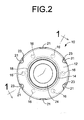
- the metallic mass 12 includes a plurality of through holes (e.g., six through holes in the present embodiment) which extend through the metallic mass 12 in the axial direction of the metallic mass 12 with a constant circular cross sectional shape, while being equally spaced apart from each other in the circumferential direction of the metallic mass 12.
- the metallic mass 12 further includes bevels 18 formed at radially inner edges of the axially opposite end faces of the metallic mass 12, such that each of the bevels 18 extends over the corresponding axial end face and the inner circumferential surface of the metallic mass 12, for chamfering or eliminating the corresponding radially inner edges.
- each bevel is provided as a tapered cylindrical surface extending over the circumference of the metallic mass member.
- each bevel 18 is dimensioned such that the corresponding radially inner edge of the one axial end face of the metallic mass 12 is chamfered by 3.0-5.0mm at the axial end face and the inner circumferential surface of the metallic mass 12, respectively.
- the bevels 18 are inclined with respect to the center axis of the dynamic damper 10 by a predetermined inclined angle: ⁇ , preferably 10-80 degrees, more preferably, 30-60 degrees.
- the bevels 18 extend not to reach the plurality of through holes 16, and are inclined by 45 degrees with respect to the center axis of the dynamic damper 10. That is, the through holes 16 are disposed radially outwardly of the bevels in the metallic mass 12.
- the radially inner edges of the opposite axial end faces of the metallic mass 12 are chamfered at the opposite axial end faces by a predetermined radial distance which is smaller than that of the wall thickness dimension of the metallic mass 12.
- a rubber layer 20 as an elastic covering layer is fixed in close contact with the surface of the metallic mass 12.
- the rubber layer 20 is a thin rubber layer that extends over the entire area of the surface of the metallic mass 12 with a substantially constant thickness.
- the rubber layer 20 has a thickness of 0.5-5.0mm, more preferably of 1.0-3.0mm.
- the rubber layer 20 further extends into the through holes 16, thereby providing filling rubber portions 22 as an integral parts of the rubber layer 20 which fill the through holes 16, respectively.
- the radially outer part of the rubber layer 20 located on the outer circumferential surface of the metallic mass 12 and the radially inner part of the rubber layer 20 located on the inner circumferential surface of the metallic mass 12 are connected with each other via the filling rubber portions 22 of the rubber layer 20.
- the pair of the elastic support members 14 are formed integrally with and on the respective axially opposite sides of the metallic mass 12, so as to extend in axially outward directions from the respective axially opposite ends of the metallic mass 12.
- Each of the elastic support members 14 is a generally hollow cylindrical member and extends axially outwardly and radially inwardly from the corresponding axial end face of the metallic mass 12 so as to form a tapered cylindrical configuration whose diameter is reduced in he axially outward direction thereof at a generally constant tapered angle.
- Two cylindrical fixing portions 24 are integrally formed with and extend axially outwardly from the respective axially protruding end portions (small diameter end portions) of the elastic support members 14 with substantially constant inner and outer diameters.
- One of the two cylindrical fixing portions 24 has an annular groove 26 formed in its outer circumferential surface so as to extend in its circumferential direction. The annular groove 26 is adapted to receive a retainer band (not shown).
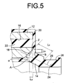
- the large diameter end portion of the inner circumferential surface of each of the elastic support members 14 may be interpreted as a point: A of intersection of an axially outward continuation of the inner circumferential surface of the rubber layer 20 and an axially inward continuation of the inner circumferential surface of the corresponding elastic support member 14.
- the intersection point: A is arranged to be located axially inwardly of the corresponding axial end face of the metallic mass 12 by a predetermined axial distance: La.
- each elastic support member 14 is positioned relative to the metallic mass 12 such that a centerline 28 of the elastic support member 14 in its width direction intersects the corresponding bevel 18 of the metallic mass 12.
- the centerline 28 may intersect any portions of the bevel 18 without specific limitation.
- the centerline 28 may intersect the substantially central portion of the corresponding bevel as measured in its width direction.
- the sum of the above-indicated inclined angle: ⁇ of the one of the bevels 18 and the tapered angle of the corresponding elastic support member 14, that is, the angle: ⁇ between the centerline 28 of the elastic support member 14 and the bevel 18 is preferably determined within a range of 45-90 degrees, more preferably 60-80 degrees. In this embodiment, the angle: ⁇ between the centerline 28 and the bevel 18 has an angular value of about 70 degrees.
- each of the elastic support members 14 may be interpreted as a point: B of intersection of an radially inward continuation of the corresponding axial end face of the rubber layer 20 and an axially inward continuation of the outer circumferential surface of the corresponding elastic support member 14.
- the intersection point: B is arranged to be located radially inwardly of a line of intersection of the corresponding axial end face and the corresponding bevel 18 of the metallic mass 12 by a predetermined radial distance: Lb.
- the dynamic damper 10 constructed as described above is installed on the drive shaft (not shown) of the vehicle such that the dynamic damper 10 is disposed radially outwardly of the drive shaft.
- the inside diameter of the fixing portions 24 is made slightly smaller than the outside diameter of the drive shaft, the dynamic damper 10 is firmly fixed on the drive shaft such that the inner circumferential surfaces of the fixing portions 24 are forcedly and closely fitted onto the respective portions of the outer circumferential surface of the drive shaft, based on elasticity of the fixing portions 24.
- the retainer bands (not shown) made of a hard material such as metal may be fixedly received in the annular groove 26, as needed, so that the fixing portions 24 are further firmly fixed to the respective portions of the drive shaft such that the fixing portions 24 are immovable in the axial and circumferential direction of the drive shaft.
- the metallic mass 12 is generally coaxial with and radially outwardly disposed of the drive shaft with a given radial spacing therebetween, while being elastically supported by the elastic support members 14, for thereby constitute a secondary vibration system with respect to a primary vibration system as of the drive shaft, in order to absolve or reduce the vibration of the drive shaft.
- the dynamic damper 10 is arranged to have a reduced ratio of its spring value as measured in the axial direction to the spring value as measured in the radial or torsional direction.
- the rubber layer 20, the pair of the elastic support members 14 and the fixing portions 24 are formed into an integrally vulcanized product of the elastic body by vulcanizing a rubber material for forming the rubber layer 20, the elastic support members 14 and the fixing portions 24.
- the elastic body is secured to the metallic mass 12 embodied therein.
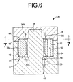
- a mold 30 having a mold cavity 36 the configuration of which corresponds to that of the rubber layer 20 and the elastic support members 14 and the cylindrical fixing portions 24.
- a suitable rubber material is poured into the mold cavity 36 of the mold 30 and is then vulcanized, thereby effectively providing the rubber layer 20, the pair of the elastic support members 14 and the cylindrical fixing portions 24.
- the mold 30 includes an upper mold half 32 and a lower mold half 34 which are butted together at a parting plane extending in the direction perpendicular to the longitudinal direction to thereby define therebetween the mold cavity 36.
- the mold cavity 36 includes a first cavity portion 36a whose configuration corresponds to that of the desired rubber layer 20, and a second cavity portion 36b whose configuration corresponds to the outer circumferential surfaces of the elastic support members 14 and the fixing portions 24.
- the first and second cavity portions cooperate with each other to constitute the single mold cavity 36.
- the lower mold half 34 has a cavity open in the upper end face at which the lower mold half 34 is butted to the upper mold half 32.
- the central portion of the bottom surface of the cavity of the lower mold half 34 protrudes in the axially upward direction so as to form a core portion 38.
- the core portion 38 has the outer circumferential surface which provides a molding surface corresponding to the inner surfaces of the rubber layer 20 and the pair of elastic support members 14 and the fixing portions 24.
- the lower mold half 34 is further formed with a through hole 40 serving as a gate through which the suitable rubber material is poured or injected into the mold cavity 36.
- the metallic mass 12 formed of sintered metal as described above is required to be suitably positioned relative to the mold cavity 36 such that the metallic mass 12 is located diametrically central portion of the first cavity 36a, while being held in co-axial relationship with the first cavity portion 36a.
- the molding surface defining the first cavity portion 36a includes a plurality of supporting protrusions 42 at its axially opposite end portions.
- six supporting protrusions 42 are formed at each axial end portion of the first cavity portion 36a, such that the six supporting protrusions 42 are spaced apart from each other in the circumferential direction at substantially constant intervals, and protrude radially inwardly from the respective circumferential portions of the molding surface with a given radial distance.
- the outer circumferential surface of the metallic mass 12 is held in contact with the radially inwardly protruding end portion of the supporting protrusions 42 at its axially opposite end portions, so that the metallic mass 12 is effectively positioned relative to the first mold cavity portion 36a in the diametrical direction of the mold 30.
- Each of the semi-circular protrusions 44 is integrally formed in the axially-outward end portion of the corresponding supporting protrusion 42 so as to protrude radially inwardly from the outer circumferential surface of the supporting protrusion 42.
- the metallic mass 12 are held in abutting contact with the four semi-circular protrusions 42 which are formed at each of the axially opposite end portions of the first mold cavity portion 36a, so that the metallic mass 12 is effectively positioned with respect to the first mold cavity portion 36a in the axial direction of the mold 30.
- the metallic mass 12 may be previously subjected to suitable treatments including washing and degreasing, as needed.
- each supporting protrusion 42 has a tapered shape such that the width or the circumferential length of the supporting protrusion 42 is decreased as the supporting protrusion 42 protrudes radially inwardly, so that the supporting protrusion 42 extends in the axial direction of the first mold cavity portion 36a with a generally semi-circular shape as seen in the transverse cross section.
- This arrangement makes it possible to effectively reduce the required contact surface area of the supporting protrusions 42 for contact with the outer circumferential surface of the metallic mass 12 for supporting and positioning the metallic mass 12 in the first mold cavity portion 36a, so that the substantially entire area of the surface of the metallic mass 12 can be effectively covered with the rubber layer 20.
- the metallic mass 12 is substantially entirely covered with the rubber layer 20 and partially exposed to the atmosphere at respective portions corresponding to the supporting protrusions 42, as shown in Fig. 9. That is, the rubber layer 20 includes six cutouts 21 formed on each of the axially opposite end portions of the metallic mass 12. The six cutouts 21 are spaced apart from each other in the circumferential direction of the metallic mass 12 at substantially constant intervals while having a semi-circular shape in its transverse cross section.
- the rubber layer 20 further includes four cutouts 23 formed in each of the axially opposite end faces of the metallic mass 12. The four cutouts 23 are spaced apart from each other in the circumferential direction of the metallic mass 12, while protruding radially inwardly from the circumference of the corresponding axial end face of the metallic mass 12 with the semi-circular shape.
- the rubber layer 20 and the pair of the elastic support members 14 and the cylindrical fixing portions 24 are integrally formed of a single elastic body wherein the metallic mass 12 is embedded as an integral part, upon vulcanization of a rubber material for forming the rubber layer 20, the elastic support members, 14 and the fixing portions 24.
- the metallic mass 12 is covered with the rubber layer 20 over its substantially entire area.
- the rubber layer 20 is firmly fixed in close contact with the surface of the metallic mass 12 owing to a filling pressure of the rubber material in the mold cavity 36 and shrinkage of the rubber material in the vulcanization process.
- the metallic mass 12 has a relatively large axial length: Ld and accordingly has a sufficiently large mass.
- the each elastic support member 14 extends axially inwardly from the corresponding axial end face of the metallic mass 12, so that the elastic support member 14 has a sufficiently large effective free length: Lc, while having a reduced axial length of its protruding end portion that protrudes axially outwardly from the corresponding axial end face of the metallic mass 12, whereby the overall axial length: Le of the dynamic damper 10 can be made smaller.
- the present dynamic damper 10 can meet the above indicated both requirements, namely the sufficiently large mass of the metallic mass 12 and the relatively small size of the overall dynamic damper 10.
- the bevels 18 formed at radially inner edges of the axially opposite end faces of the metallic mass 12 permit that the axially inner end portions of the elastic support members 14 protrudes axially inwardly of the opposite axial end faces of the metallic mass 12. This arrangement is effective to obtain a desired effective free length: Lc of the each elastic support member 14.
- the large diameter or axially inner end portions of the elastic support members 14 are secured to the bevels 18 of the metallic mass 12, respectively.
- This arrangement is effective to ease or relax the stress concentration generated in the boundary between the axially inner end portions of the elastic support members 14 and the axially opposite end faces of the metallic mass 12, leading to improved durability of the elastic mass members 14.
- the metallic mass 12 is formed of the sintered metal, so that the surface of the metallic mass 12 is effectively rugged due to the presence of the metallic particles which are bonded together in the solid-state by sintering.
- An inner circumferential surface of the rubber layer 20 is brought into close contact with the rugged surface of the metallic mass 12 upon vulcanization of the rubber material to form the rubber layer 20, and is accordingly made rugged along with the rugged surface of the metallic mass 12.
- the rugged surface of the metallic mass 12 and the rugged surface of the rubber layer 20 are mechanically engaged with each other by their raised and recessed portions engaged with each other as seen in a microscopic level.
- the dynamic damper 10 constructed according to the present embodiment can exhibit a desired strength and durability enough to endure the significantly large vibrational load applied thereto, thereby exhibiting desired vibration damping effect with high stability.
- the rubber layer 20 and the metallic mass 12 are firmly secured to each other, even when an excessively large vibrational load is applied to the dynamic damper 10 in the direction perpendicular to the axial direction, and when an initial load in the axial direction is applied to the dynamic damper 10 so as to install the dynamic damper 10 onto the drive shaft, while when an impact load in the axial direction is applied to the dynamic damper 10 due to the collision of the small pieces of fly rocks with the dynamic damper 10 or the like.
- the dynamic damper 10 is capable of preventing undesirable displacement of the rubber layer 20 and the metallic mass 12 relative to each other at the interface therebetween, thereby exhibiting an desirable vibration damping effect with high stability.
- the through holes 16 formed through the metallic mass 12 are filled with the rubber layer 20 to thereby provide the filling rubber portions 22 by which the radially inner and outer parts of the rubber layer 20 which are located on the inner and outer circumferential surfaces of the metallic mass 12 are directly connected with each other.
- This arrangement permits an improved bonding or fixing stability of the rubber layer 20 with respect to the surface of the metallic mass 12 without using an adhesive interposed between the rubber layer 20 and the metallic mass 12.
- the through holes 16 formed through the metallic mass 12 are filled with the rubber layer 20 to thereby provide the filling rubber portions 22 by which the radially inner and outer parts of the rubber layer 20 which are located on the inner and outer circumferential surfaces of the metallic mass 12 are directly connected with each other.
- This arrangement permits a sufficient bonding or fixing stability of the rubber layer 20 with respect to the surface of the metallic mass 12 without using an adhesive interposed between the rubber layer 20 and the metallic mass 12.
- the metallic mass 12 made of a sintered metal is employed in the illustrated embodiment, a metallic mass formed by forging may also be employed.
- the metallic mass 12 which is formed of carbon steel or the like by hot forging.
- Such a cylindrical metallic mass 12 may be formed by closed die forging such that a disk-shaped blank previously heated is placed within a molding cavity of a cylindrical die and the central portion of the blank is punched out so as to form a bore thereof, or alternatively such that an annular-shaped blank previously heated is placed within the molding cavity of the die and the central portion of the blank is punched so as to expand the bore thereof, for example.
- the thus formed metallic mass 12 is cooled in the process of a direct thermal refining from forging temperature wherein the metallic mass 12 is cooled under a suitable temperature control, or in an asforged process wherein the metallic mass 12 is exposed to the atmosphere with no temperature control. In both cases, the cooled metallic mass 12 is subjected to a scale removal treatment for removing a scale formed thereon during the cooling method as indicated above, whereby is obtained the desired metallic mass 12 whose scale is removed.
- the scale removal treatment as indicated above is performed on the forging in order to remove or clean the scale, i.e., a thin layer of oxides formed or deposited on the surface of the forging.
- the scale removal treatment may be executed according to a suitable method such as a shot blasting wherein a stream of shots consisting of steel shots or wire-cuts which are accelerated by the air pressure or a circulation force, is applied or collided to the entire surface of the forging member.
- the oxides layer of the metallic mass 12 is completely removed from the substantially entire surface of the metallic mass 12, and the resultant entire surface of the metallic mass 12 is effectively roughed or rugged.
- the metallic mass 12 has a surface roughness ranging from 30 ⁇ m to 200 ⁇ m, more preferably, ranging from 50 ⁇ m to 100 ⁇ m as measured ten-point means roughness Rz scale.
- the through holes 16 and the bevels 18 to be formed in the metallic mass 12 may be formed at the same time when the metallic mass 12 is formed by closed die forging, or alternatively be formed after the formation of the metallic mass 12 by the forging.
- the rubber layer 20 is fixed in close contact with the surface of the metallic mass 12 without using the adhesive applied therebetween.
- the rubber layer 20 may also be fixed to the metallic mass 12 via the adhesive interposed therebetween upon vulcanization of the rubber material for forming he rubber layer 20.
- the rubber layer 20 is secured to the metallic mass 12 with further improved fixing strength, owing to the rugged surface of the metallic mass 12, so that the dynamic damper 10 where the rubber layer 20 is secured to the metallic mass 12 by using the adhesive, also exhibits the same effect as in the illustrated embodiment.
- the number, size and shape in cross section of the through holes 16 formed through the metallic mass member may be suitably determined taking into account the required vibration damping characteristics of the dynamic damper 10 and the size of the employed metallic mass member, since the mass of the metallic mass member and the fixing stability between the elastic covering layer and the metallic mass member are directly influenced by the number and the size of the through holes 16.
- the dynamic damper of the present invention may be suitably positioned relative to the drive shaft by utilizing a small- and a large-diameter portion formed in the drive shaft.
- the structure of the mold for molding the dynamic damper is not particularly limited, provided the metallic mass member is positioned and supported by means of a plurality of supporting protrusions.
- the mold consisting of a plurality of divided components that are butted together at a parting plane(s) extending in the longitudinal direction of the mold to thereby define therebetween the mold cavity.
- the number of the supporting protrusions may be suitably determined and is not particularly limited to the number in the illustrated embodiment.
- the principle of the present invention is also applicable to a double mass-type dynamic damper wherein two cylindrical metallic mass members are disposed in series in the axial direction with a given axial spacing therebetween, and elastic support members are secured to axially opposite end faces of the respective cylindrical metallic mass members and connected to each other in the axial direction.
Landscapes
- Engineering & Computer Science (AREA)
- General Engineering & Computer Science (AREA)
- Mechanical Engineering (AREA)
- Vibration Prevention Devices (AREA)
- Motor Power Transmission Devices (AREA)
Abstract
Description
Claims (15)
- A dynamic damper (10) mounted on a rod-shaped oscillating member, comprising:a generally cylindrical metallic mass member (12) formed of sintered metal or forging, and disposed radially outwardly of the oscillating member;a pair of elastic support members (14) which are formed on and extend axially outwardly and radially inwardly from axially opposite sides of said metallic mass member so as to have a tapered cylindrical configuration, said pair of elastic support members being adapted to elastically support said metallic mass member with respect to the rod-shaped oscillating member; andan elastic covering layer (20) integrally formed with said pair of elastic support members and being fixed in close contact with a substantially entire area of a surface of said metallic mass member for covering said substantially entire area of said surface of said metallic mass member, said metallic mass member having bevels (18) in the form of tapered cylindrical surfaces extending over a circumference of said metallic mass member, which are formed at radially inner edges of axially opposite end faces of said metallic mass member, respectively, each of said bevels extending over a corresponding one of said axially opposite end faces and an inner circumferential surface of said metallic mass member to thereby chamfer the corresponding one of said radially inner edges, said pair of elastic support members are fixed at large diameter end portions thereof to said bevels, respectively.
- A dynamic damper (10) according to claim 1, wherein said elastic support members (14) have respective inner circumferential surfaces whose large-diameter end portions located axially inwardly of the axially opposite end faces of the metallic mass member.
- A dynamic damper (10) according to claims 1 or 2, wherein each of said bevels (18) is inclined by 10-80 degrees with respect to the center axis of the dynamic damper.
- A dynamic damper (10) according to any one of claims 1-3, wherein each of said elastic support members (14) is fixed to the corresponding one of said bevels (18) of said metallic mass member such that a centerline of said elastic support member which extends through a center portion of said elastic support member in a width direction of said elastic support member; is intersect with the corresponding bevel of said metallic mass member.
- A dynamic damper (10) according to claim 4, wherein said centerline of said each of said elastic support member (14) is intersect with a substantially central portion of the corresponding one of said bevels (18) in the width direction thereof.
- A dynamic damper (10) according to claims 4 or 5, wherein a sum of an inclined angle of each of said bevels (18) with respect to the center axis of said dynamic damper and a tapered angle of the corresponding one of said elastic support members (14) is held within a range of 45-90 degrees.
- A dynamic damper (10) according to any one of claims 1-6, wherein said elastic support members have respective outer circumferential surfaces whose large-diameter end portions located on the respective bevels of said metallic mass member, as seen in an axial projection of said dynamic damper.
- A dynamic damper (10) according to any one of claims 1-7, wherein said large-diameter end portions of said outer circumferential surfaces of said elastic support members (14) are located radially inwardly of respective lines of intersections of axial end faces and bevels (18) of said metallic mass member (12).
- A dynamic damper (10) according to any one of claims 1-8, wherein said elastic covering layer (20) is fixed in close contact with a surface of said metallic mass member (12) without using an adhesive.
- A dynamic damper (10) according to any one of claims 1-9, wherein said metallic mass member (12) includes a plurality of through holes (16) formed therethrough so as to extend in an axial direction of said metallic mass member, said plurality of through holes being filled with said elastic covering layer (20).
- A dynamic damper (10) according to claim 10, wherein said plurality of through holes (16) are disposed radially outwardly of said bevels (18) of said metallic mass member (12).
- A dynamic damper (10) according to any one of claims 1-11, wherein said surface of the metallic mass member (12) has a ten-point mean roughness Rz within a range from 30µm to 200µm.
- A dynamic damper (10) according to any one of claim 1-11, wherein said surface of said metallic mass member (12) has a ten-point mean roughness Rz within a range from 50µm to 100µm.
- A dynamic damper (10) according to claim 1, wherein said bevels (18) are dimensioned such that said radially inner edges of said axially opposite end faces of said metallic mass member are chamfered by 3.0-5.0mm in an axial direction and a radial direction perpendicular to the axial direction of said metallic mass member, respectively.
- A dynamic damper (10) according to any one of claims 1-14, wherein said elastic covering layer has a thickness within a range of 0.5-5.0mm.
Applications Claiming Priority (2)
| Application Number | Priority Date | Filing Date | Title |
|---|---|---|---|
| JP2000290149A JP2002098193A (en) | 2000-09-25 | 2000-09-25 | Cylindrical dynamic damper |
| JP2000290149 | 2000-09-25 |
Publications (3)
| Publication Number | Publication Date |
|---|---|
| EP1191252A2 true EP1191252A2 (en) | 2002-03-27 |
| EP1191252A3 EP1191252A3 (en) | 2003-01-22 |
| EP1191252B1 EP1191252B1 (en) | 2003-12-17 |
Family
ID=18773422
Family Applications (1)
| Application Number | Title | Priority Date | Filing Date |
|---|---|---|---|
| EP01101848A Expired - Lifetime EP1191252B1 (en) | 2000-09-25 | 2001-01-26 | Cylindrical dynamic damper whose size is compact and whose mass member has large mass |
Country Status (4)
| Country | Link |
|---|---|
| US (2) | US6550754B2 (en) |
| EP (1) | EP1191252B1 (en) |
| JP (1) | JP2002098193A (en) |
| DE (1) | DE60101529T2 (en) |
Cited By (1)
| Publication number | Priority date | Publication date | Assignee | Title |
|---|---|---|---|---|
| US7635118B2 (en) | 2005-01-20 | 2009-12-22 | Tokai Rubber Industries, Ltd. | Cylindrical dynamic damper |
Families Citing this family (19)
| Publication number | Priority date | Publication date | Assignee | Title |
|---|---|---|---|---|
| JP2003139196A (en) | 2001-10-31 | 2003-05-14 | Tokai Rubber Ind Ltd | Dynamic damper |
| JP4046010B2 (en) * | 2002-08-27 | 2008-02-13 | 東海ゴム工業株式会社 | Dynamic damper |
| CA2511210A1 (en) * | 2004-07-14 | 2006-01-14 | The Pullman Company | Multi-direction tuned mass damper with unique assembly |
| KR100790661B1 (en) * | 2004-08-10 | 2008-01-02 | 미츠비시 쥬고교 가부시키가이샤 | Cask Buffer |
| JP4496488B2 (en) * | 2005-01-20 | 2010-07-07 | 東海ゴム工業株式会社 | Cylindrical dynamic damper |
| JP4669329B2 (en) * | 2005-06-15 | 2011-04-13 | 本田技研工業株式会社 | Dynamic damper |
| US20060283678A1 (en) * | 2005-06-15 | 2006-12-21 | Honda Motor Co., Ltd. | Dynamic damper |
| JP4238892B2 (en) * | 2006-03-30 | 2009-03-18 | 東海ゴム工業株式会社 | Fluid filled cylindrical vibration isolator |
| US8141614B2 (en) * | 2009-07-01 | 2012-03-27 | Harmonic Design | Expanding coupling means for powered window covering |
| FR2949250B1 (en) * | 2009-08-24 | 2012-01-06 | Aliaxis R & D Sas | AMORTIZING BRIDGE |
| KR20130048816A (en) * | 2011-11-03 | 2013-05-13 | 삼성전자주식회사 | Damper for decreasing a piping vibration |
| US9410597B2 (en) * | 2014-04-02 | 2016-08-09 | Dayco Ip Holdings, Llc | Radial vibration dampers for rotating shafts |
| KR101648427B1 (en) * | 2014-12-16 | 2016-08-16 | 주식회사 대흥알앤티 | Dynamic damper |
| KR101746578B1 (en) | 2015-12-14 | 2017-06-13 | 현대자동차주식회사 | Dynamic damper use for a drive shaft of a car |
| KR101786314B1 (en) * | 2016-03-21 | 2017-10-17 | 현대자동차주식회사 | Dynamic damper assembly |
| KR101817998B1 (en) | 2017-04-18 | 2018-01-15 | 서한산업(주) | A dynamic damper for a shaft |
| DE102019107885B4 (en) * | 2019-03-27 | 2023-09-21 | Vibracoustic Se | Vibration absorber |
| IT202100006680A1 (en) * | 2021-03-19 | 2022-09-19 | Leonardo Spa | PASSIVE VIBRATION DAMPING DEVICE FOR AIRCRAFT |
| US11732770B2 (en) * | 2021-06-25 | 2023-08-22 | Hyundai Motor Company | Mass damper for vehicle air conditioning system |
Family Cites Families (12)
| Publication number | Priority date | Publication date | Assignee | Title |
|---|---|---|---|---|
| US2749160A (en) * | 1949-08-09 | 1956-06-05 | Gen Tire & Rubber Co | Steel backed rubber bushings |
| DE68907665T2 (en) | 1988-08-27 | 1993-11-11 | Tokai Rubber Ind Ltd | Dynamic damper. |
| JPH02190641A (en) | 1989-01-17 | 1990-07-26 | Kinugawa Rubber Ind Co Ltd | Dynamic damper for drive shaft |
| JPH0337450A (en) * | 1989-06-30 | 1991-02-18 | Kinugawa Rubber Ind Co Ltd | Dynamic damper |
| JPH0637915A (en) | 1992-07-17 | 1994-02-10 | Nippon Avionics Co Ltd | Remote meter reading device |
| DE4334316C2 (en) * | 1993-10-08 | 1997-01-23 | Freudenberg Carl Fa | Vibration damper |
| JP3076718B2 (en) | 1994-03-11 | 2000-08-14 | 東海ゴム工業株式会社 | Dynamic damper |
| JP3430669B2 (en) | 1994-05-13 | 2003-07-28 | 東海ゴム工業株式会社 | Rod-shaped vibrator with dynamic damper |
| JPH08219210A (en) | 1995-02-13 | 1996-08-27 | Tokai Rubber Ind Ltd | Anti-vibration support |
| US6065742A (en) * | 1996-09-13 | 2000-05-23 | Lord Corporation | Multi-directional tuned vibration absorber |
| US6216833B1 (en) * | 1999-07-22 | 2001-04-17 | Bridgestone/Firestone, Inc. | Vibration damper and method of making same |
| JP2001280420A (en) | 2000-03-30 | 2001-10-10 | Tokai Rubber Ind Ltd | Cylindrical dynamic damper and method of manufacturing the same |
-
2000
- 2000-09-25 JP JP2000290149A patent/JP2002098193A/en active Pending
-
2001
- 2001-01-26 DE DE60101529T patent/DE60101529T2/en not_active Expired - Lifetime
- 2001-01-26 EP EP01101848A patent/EP1191252B1/en not_active Expired - Lifetime
- 2001-01-31 US US09/774,782 patent/US6550754B2/en not_active Expired - Fee Related
-
2002
- 2002-09-11 US US10/241,654 patent/US6857623B2/en not_active Expired - Fee Related
Cited By (1)
| Publication number | Priority date | Publication date | Assignee | Title |
|---|---|---|---|---|
| US7635118B2 (en) | 2005-01-20 | 2009-12-22 | Tokai Rubber Industries, Ltd. | Cylindrical dynamic damper |
Also Published As
| Publication number | Publication date |
|---|---|
| JP2002098193A (en) | 2002-04-05 |
| DE60101529T2 (en) | 2004-11-11 |
| US6550754B2 (en) | 2003-04-22 |
| DE60101529D1 (en) | 2004-01-29 |
| EP1191252B1 (en) | 2003-12-17 |
| US20030006541A1 (en) | 2003-01-09 |
| US6857623B2 (en) | 2005-02-22 |
| US20020036124A1 (en) | 2002-03-28 |
| EP1191252A3 (en) | 2003-01-22 |
Similar Documents
| Publication | Publication Date | Title |
|---|---|---|
| EP1191252B1 (en) | Cylindrical dynamic damper whose size is compact and whose mass member has large mass | |
| EP1191250B1 (en) | Cylindrical dynamic damper exhibiting high bonding strength between mass member and elastic support members | |
| US6499730B1 (en) | Dynamic damper having generally cylindrical shape and method of producing the same | |
| US4667764A (en) | Resilient mounting device for transversely disposed engine of front-engine front-drive vehicle | |
| US4612695A (en) | Method of manufacturing a hollow cam shaft | |
| EP0423243B1 (en) | Torsional vibration damper | |
| US6682060B2 (en) | Dynamic damper | |
| US20080023899A1 (en) | Cylindrical vibration-damping device and method of producing the same, and vibration-damping structure including the cylindrical vibration-damping device | |
| US6981579B2 (en) | Dynamic damper | |
| US8136646B2 (en) | Cylindrical dynamic damper | |
| CN111412264B (en) | Gear, gear transmission and method for manufacturing gear | |
| CN100380017C (en) | Cylindrical Dynamic Shock Absorber | |
| EP3333449B1 (en) | Dynamic damper | |
| JP2004500989A (en) | Method of manufacturing torsional vibration damper housing, especially housing for viscous torsional vibration damper | |
| US5277410A (en) | Upper support for suspension system having two outer rigid members, and method of manufacturing the same | |
| WO1996007036A1 (en) | Dynamic damper and molding material therefor and method of manufacturing the same | |
| KR100650368B1 (en) | Car wheel | |
| JP2000225941A (en) | Anti-vibration rubber bush for railroad vehicle axle beam device | |
| JP2007139041A (en) | Dynamic damper | |
| JP2007177830A (en) | Dynamic damper and hollow propeller with it | |
| JP4669329B2 (en) | Dynamic damper | |
| JP2000170837A (en) | Anti-vibration device with stopper | |
| JP2004019847A (en) | Dynamic damper | |
| JPH10196722A (en) | Damper | |
| JP2006177525A (en) | Cylindrical dynamic damper |
Legal Events
| Date | Code | Title | Description |
|---|---|---|---|
| PUAI | Public reference made under article 153(3) epc to a published international application that has entered the european phase |
Free format text: ORIGINAL CODE: 0009012 |
|
| 17P | Request for examination filed |
Effective date: 20010126 |
|
| AK | Designated contracting states |
Kind code of ref document: A2 Designated state(s): AT BE CH CY DE DK ES FI FR GB GR IE IT LI LU MC NL PT SE TR |
|
| AX | Request for extension of the european patent |
Free format text: AL;LT;LV;MK;RO;SI |
|
| PUAL | Search report despatched |
Free format text: ORIGINAL CODE: 0009013 |
|
| AK | Designated contracting states |
Kind code of ref document: A3 Designated state(s): AT BE CH CY DE DK ES FI FR GB GR IE IT LI LU MC NL PT SE TR |
|
| AX | Request for extension of the european patent |
Free format text: AL;LT;LV;MK;RO;SI |
|
| GRAH | Despatch of communication of intention to grant a patent |
Free format text: ORIGINAL CODE: EPIDOS IGRA |
|
| AKX | Designation fees paid |
Designated state(s): DE FR GB |
|
| GRAS | Grant fee paid |
Free format text: ORIGINAL CODE: EPIDOSNIGR3 |
|
| GRAA | (expected) grant |
Free format text: ORIGINAL CODE: 0009210 |
|
| AK | Designated contracting states |
Kind code of ref document: B1 Designated state(s): DE FR GB |
|
| REG | Reference to a national code |
Ref country code: GB Ref legal event code: FG4D |
|
| REG | Reference to a national code |
Ref country code: IE Ref legal event code: FG4D |
|
| REF | Corresponds to: |
Ref document number: 60101529 Country of ref document: DE Date of ref document: 20040129 Kind code of ref document: P |
|
| ET | Fr: translation filed | ||
| REG | Reference to a national code |
Ref country code: IE Ref legal event code: MM4A |
|
| PLBE | No opposition filed within time limit |
Free format text: ORIGINAL CODE: 0009261 |
|
| STAA | Information on the status of an ep patent application or granted ep patent |
Free format text: STATUS: NO OPPOSITION FILED WITHIN TIME LIMIT |
|
| 26N | No opposition filed |
Effective date: 20040920 |
|
| PGFP | Annual fee paid to national office [announced via postgrant information from national office to epo] |
Ref country code: FR Payment date: 20050110 Year of fee payment: 5 |
|
| PGFP | Annual fee paid to national office [announced via postgrant information from national office to epo] |
Ref country code: GB Payment date: 20050126 Year of fee payment: 5 |
|
| PG25 | Lapsed in a contracting state [announced via postgrant information from national office to epo] |
Ref country code: GB Free format text: LAPSE BECAUSE OF NON-PAYMENT OF DUE FEES Effective date: 20060126 |
|
| PG25 | Lapsed in a contracting state [announced via postgrant information from national office to epo] |
Ref country code: FR Free format text: LAPSE BECAUSE OF NON-PAYMENT OF DUE FEES Effective date: 20060131 |
|
| GBPC | Gb: european patent ceased through non-payment of renewal fee |
Effective date: 20060126 |
|
| REG | Reference to a national code |
Ref country code: FR Ref legal event code: ST Effective date: 20060929 |
|
| REG | Reference to a national code |
Ref country code: DE Ref legal event code: R084 Ref document number: 60101529 Country of ref document: DE |
|
| REG | Reference to a national code |
Ref country code: DE Ref legal event code: R084 Ref document number: 60101529 Country of ref document: DE Effective date: 20110614 |
|
| PGFP | Annual fee paid to national office [announced via postgrant information from national office to epo] |
Ref country code: DE Payment date: 20140122 Year of fee payment: 14 |
|
| REG | Reference to a national code |
Ref country code: DE Ref legal event code: R119 Ref document number: 60101529 Country of ref document: DE |
|
| PG25 | Lapsed in a contracting state [announced via postgrant information from national office to epo] |
Ref country code: DE Free format text: LAPSE BECAUSE OF FAILURE TO SUBMIT A TRANSLATION OF THE DESCRIPTION OR TO PAY THE FEE WITHIN THE PRESCRIBED TIME-LIMIT Effective date: 20150801 |