EP1190910A1 - Weather strip - Google Patents
Weather strip Download PDFInfo
- Publication number
- EP1190910A1 EP1190910A1 EP01915680A EP01915680A EP1190910A1 EP 1190910 A1 EP1190910 A1 EP 1190910A1 EP 01915680 A EP01915680 A EP 01915680A EP 01915680 A EP01915680 A EP 01915680A EP 1190910 A1 EP1190910 A1 EP 1190910A1
- Authority
- EP
- European Patent Office
- Prior art keywords
- section
- hollow chamber
- body opening
- weather strip
- seal
- Prior art date
- Legal status (The legal status is an assumption and is not a legal conclusion. Google has not performed a legal analysis and makes no representation as to the accuracy of the status listed.)
- Granted
Links
Images


Classifications
-
- B—PERFORMING OPERATIONS; TRANSPORTING
- B60—VEHICLES IN GENERAL
- B60J—WINDOWS, WINDSCREENS, NON-FIXED ROOFS, DOORS, OR SIMILAR DEVICES FOR VEHICLES; REMOVABLE EXTERNAL PROTECTIVE COVERINGS SPECIALLY ADAPTED FOR VEHICLES
- B60J10/00—Sealing arrangements
- B60J10/80—Sealing arrangements specially adapted for opening panels, e.g. doors
- B60J10/84—Sealing arrangements specially adapted for opening panels, e.g. doors arranged on the vehicle body
-
- B—PERFORMING OPERATIONS; TRANSPORTING
- B60—VEHICLES IN GENERAL
- B60J—WINDOWS, WINDSCREENS, NON-FIXED ROOFS, DOORS, OR SIMILAR DEVICES FOR VEHICLES; REMOVABLE EXTERNAL PROTECTIVE COVERINGS SPECIALLY ADAPTED FOR VEHICLES
- B60J10/00—Sealing arrangements
- B60J10/15—Sealing arrangements characterised by the material
- B60J10/16—Sealing arrangements characterised by the material consisting of two or more plastic materials having different physical or chemical properties
-
- B—PERFORMING OPERATIONS; TRANSPORTING
- B60—VEHICLES IN GENERAL
- B60J—WINDOWS, WINDSCREENS, NON-FIXED ROOFS, DOORS, OR SIMILAR DEVICES FOR VEHICLES; REMOVABLE EXTERNAL PROTECTIVE COVERINGS SPECIALLY ADAPTED FOR VEHICLES
- B60J10/00—Sealing arrangements
- B60J10/20—Sealing arrangements characterised by the shape
- B60J10/24—Sealing arrangements characterised by the shape having tubular parts
- B60J10/248—Sealing arrangements characterised by the shape having tubular parts having two or more tubular cavities, e.g. formed by partition walls
-
- Y—GENERAL TAGGING OF NEW TECHNOLOGICAL DEVELOPMENTS; GENERAL TAGGING OF CROSS-SECTIONAL TECHNOLOGIES SPANNING OVER SEVERAL SECTIONS OF THE IPC; TECHNICAL SUBJECTS COVERED BY FORMER USPC CROSS-REFERENCE ART COLLECTIONS [XRACs] AND DIGESTS
- Y10—TECHNICAL SUBJECTS COVERED BY FORMER USPC
- Y10T—TECHNICAL SUBJECTS COVERED BY FORMER US CLASSIFICATION
- Y10T428/00—Stock material or miscellaneous articles
- Y10T428/13—Hollow or container type article [e.g., tube, vase, etc.]
- Y10T428/1352—Polymer or resin containing [i.e., natural or synthetic]
- Y10T428/139—Open-ended, self-supporting conduit, cylinder, or tube-type article
Definitions
- the present invention relates to a weather strip fitted to a body opening section of a motor vehicle.
- a weather strip 4 as is seen in Fig. 2 is used on occasions.
- This weather strip 4 is of a type coupling a fitting base section (welt) 5 integrally with a hollow section (strip) 6.
- the fitting base section 5 sandwiches a body flange 3.
- the hollow section 6 has a cross section shaped approximately into numeral 8, and is constituted of a abutting section 7 which is formed with a seal hollow chamber 7a, and a middle section 8 which is integrated with the abutting section 7 and is provided with a hollow chamber 8a.
- the fitting base section 5 has a core material 9, and is shaped approximately into U.
- the fitting base section 5 has an internal surface which is formed with flange-sandwiching lips 10, and an external surface which is formed with an ornament lip 11.
- the hollow section 6 is made of a comparatively soft elastic body such as a sponge rubber, a soft thermoplastic elastomer or the like.
- the fitting base section 5 is made of a comparatively hard material such as a solid rubber, a hard thermoplastic elastomer or the like.
- the ornament lip 11 is a section that contacts a garnish.
- deflection of the hollow section 6 in fitting sections indicated by A to I of the body opening sections 2 and 2a varies with an input direction F (F1, F2, F3 and F4) of a seal surface 12a of a door panel 12, as is seen in Fig. 3 and Fig. 4.
- the input (F1, F2 and F3) is applied in such a manner as to push the hollow section 6 toward an outside of the periphery of the body opening sections 2 and 2a.
- the input (F4) is applied in such a manner as to push the hollow section 6 toward the fitting base section 5.
- the hollow section 6 is twisted and thereby is not constant in shape (of deflection), especially, in an area where the fitting sections D, I and H change to other sections. Thereby, failures occur such as lines so generated as to increase wind noise, water tightness decreased, and external appearance deteriorated. Above all, the above phenomena notably appear at an upper corner on the front side of the center pillar 1a of the body opening section 2.
- the present invention provides such a weather strip as to allow the hollow section 6 to assume an approximately the same shape (of deflection) in each section, irrespective of the input direction of the seal surface 12a when the door panel 12 is closed.
- a weather strip forming a hollow section and a fitting base section which is fitted to a body opening section
- the hollow section being provided with a seal hollow chamber integrated with a hollow chamber, a seal surface of a door panel abutting on a side defining the seal hollow chamber, the weather strip sealing a gap between the body opening section and the door panel, a bulkhead between the seal hollow chamber and the hollow chamber is so configured as to form an opening angle not smaller than right angle toward an outside of the body opening section constantly in each section on a periphery of the body opening section, relative to an input direction of the seal surface of the door panel toward the seal hollow chamber of the weather strip in each section on the periphery of the body opening section.
- an extended line of the bulkhead in the cross sectional direction turns from the outside of the body opening section toward an inside of a vehicular body with a load inputted into the weather strip when the door panel is closed.
- the seal hollow chamber is partially pushed in such a manner as to protrude between the door panel and an outside of the periphery of the body opening section.
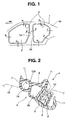
- Fig. 1 is a side view of a motor vehicle partially omitted, showing fitting sections for fitting a weather strip.
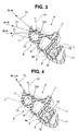
- Fig. 2 shows a cross section of a conventional weather strip.
- Fig. 3 shows a drawing for explaining an operation of the conventional weather strip in fitting sections C, G, A, E, B and F.
- Fig. 4 shows a drawing for explaining the operation of the conventional weather strip in fitting sections D, I and H.
- Fig. 5 shows a drawing for explaining a fundamental constitution (first example) of the present invention.
- Fig. 6 shows a drawing for explaining an operation of the fundamental constitution of the present invention.
- Fig. 7 shows a drawing for explaining a constitution of the weather strip according to a second example of the present invention.
- Fig. 8 shows a cross section of the weather strip, according to the second example added by a third example of the present invention.
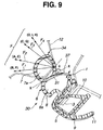
- Fig. 9 shows a cross section of the weather strip, according to the second example added by a fourth example of the present invention.
- a weather strip 30 of the present invention is provided with a fitting base section 5 having the same constitution as that of the above conventional example, and provided with a hollow section 6 having a constitution new over that of the above conventional example.
- a bulkhead 31 of the hollow section 6 or a line X-X forms right angle or right angle plus an angle ⁇ , relative to an input direction (F4) corresponding to fitting sections D, I, and H.
- the bulkhead 31 partitions the hollow section 6 into a abutting section 7 and a middle section 8.
- the line X-X runs from an inside neck section 32 to an outside neck section 33.
- the inside neck section 32 of the hollow section 6 is disposed on an inside of a periphery of a body opening section, while the outside neck section 33 of the hollow section 6 is disposed on an outside of the periphery of the body opening section.
- an input direction (F1, F2 and F3) toward the weather strip 30 corresponding to fitting sections C, G, A, E, B and F forms an angle ( ⁇ ), relative to the bulk head 31.
- the angle ( ⁇ ) is greater than right angle.
- an extended line of the bulkhead 31 turns toward an inside of a vehicular body in the clockwise direction around the inside neck section 32 on the inside of the periphery of the body opening section.
- the hollow section 6 formed as described above allows a seal hollow chamber 7a to be partially pushed in such a condition that the seal hollow chamber 7a protrudes between a door panel 12 and the outside of the periphery of a body opening section, as is seen in Fig. 6.
- the seal hollow chamber 7a assumes the same deformation, as a matter of course.
- the weather strip 30 assumes the same deflection constantly, irrespective of the input direction when the door panel 12 is closed.
- the bulkhead 31 is inclined as described above.
- the input line Y-Y is a line on which a seal surface 12a of the door panel in the fitting sections D, I and H proceeds into the weather strip, and the input line Y-Y is disposed most outside on the periphery of the body opening section.
- the seal hollow chamber 7a is formed with the top section 34 which becomes a bend point of deflection when the door panel is closed.
- the top section 34 is disposed on the input line Y-Y (which is disposed most outside on the periphery of the body opening section) or disposed in such a manner as to be deflected more outward than the input line Y-Y on the periphery of the body opening section.
- the abutting section 7 is likely to be inclined toward the outside of the periphery of the body opening sections 2 and 2a, in the input direction (F4) corresponding to the fitting sections D, I and H.
- the input directions (F1, F2 and F3) corresponding to the other fitting sections C, G, A, E, B and F the abutting section 7 assumes the same deformation, as a matter of course.
- the weather strip 30 assumes the same deflection constantly, irrespective of the input direction when the door panel 12 is closed.
- the outside neck section 33 of the weather strip 30 outside the periphery of the body opening section is formed with a notch section 35.
- the notch section 35 is disposed at one end of a bridge section 37 which has the other end defining an internal surface formed with a notch portion 36.
- the bridge section 37 is more deformable than the other sections, via the notch sections 35 and 36, in the input direction (F4) corresponding to the fitting sections D, I and H.
- the extended line of the bulkhead 31 turns toward the inside of the vehicular body in the clockwise direction around the inside neck section 32 inside the periphery of the body opening section.
- the abutting section 7 is likely to be inclined toward the outside of the periphery of the body opening sections 2 and 2a. In the input directions corresponding to the other fitting sections C, G, A, E, B and F, the abutting section 7 assumes the same deformation, as a matter of course.
- the bridge section 37 has a thickness t which is smaller than a thickness of the other sections of the hollow chamber 8a. With this, the bridge section 37 is more deformable than the other sections in the input direction (F4) corresponding to the fitting sections D, I and H.
- the extended line of the bulkhead 31 turns toward the inside of the vehicular body in the clockwise direction around the inside neck section 32 inside the periphery of the body opening section.
- the abutting section 7 is likely to be inclined toward the outside of the periphery of the body opening sections 2 and 2a.
- the abutting section 7 assumes the same deformation, as a matter of course.
- Second doing: Allowing the top section 34 of the abutting section 7 to be disposed equal to the input line Y-Y (A 0) or outside the input line Y-Y (outside the periphery of the body opening sections 2 and 2a, A > 0), the input line Y-Y being the line on which the seal surface 12a of the door panel in the fitting sections D, I and H proceeds into the weather strip, and the input line Y-Y being disposed most outside on the periphery of the body opening section.
Landscapes
- Engineering & Computer Science (AREA)
- Mechanical Engineering (AREA)
- Seal Device For Vehicle (AREA)
- Vehicle Waterproofing, Decoration, And Sanitation Devices (AREA)
Abstract
Description
Claims (4)
- In a weather strip forming a hollow section and a fitting base section which is fitted to a body opening section, the hollow section being provided with a seal hollow chamber integrated with a hollow chamber, a seal surface of a door panel abutting on a side defining the seal hollow chamber, the weather strip sealing a gap between the body opening section and the door panel, the weather strip is characterized in that a bulkhead between the seal hollow chamber and the hollow chamber is so configured as to form an opening angle not smaller than right angle toward an outside of the body opening section constantly in each section on a periphery of the body opening section, relative to an input direction of the seal surface of the door panel toward the seal hollow chamber of the weather strip in each section on the periphery of the body opening section.
- The weather strip as described in claim 1; characterized in that a top section is formed at the seal hollow chamber, the top section becoming a bend point of deflection when the door panel is closed; and that, on a front side of a center pillar, on a front side of a rear pillar, and below the rear pillar, the top section is disposed on an input line or disposed in such a manner as to be deflected more outward than the input line on the periphery of the body opening section, the input line being a line on which the seal surface of the door panel proceeds into the weather strip and the input line being disposed most outside on the periphery of the body opening section.
- The weather strip as described in claim 1 or 2, characterized in that a notch section is formed at both ends of a bridge section which is disposed outside the periphery of the body opening section and is formed at the hollow chamber, the hollow chamber opposite to the seal hollow chamber being so disposed as to be continuous with the seal hollow chamber by way of the bulkhead.
- The weather strip as described in any one of claims 1 to 3, characterized in that a thickness of the bridge section is smaller than a thickness of the other sections of the hollow chamber, the bridge section being disposed outside the periphery of the body opening section and being formed at the hollow chamber, the hollow chamber opposite to the seal hollow chamber being so disposed as to be continuous with the seal hollow chamber by way of the bulkhead.
Applications Claiming Priority (3)
| Application Number | Priority Date | Filing Date | Title |
|---|---|---|---|
| JP2000079419A JP3714844B2 (en) | 2000-03-22 | 2000-03-22 | Weather Strip |
| JP2000079419 | 2000-03-22 | ||
| PCT/JP2001/002258 WO2001070540A1 (en) | 2000-03-22 | 2001-03-22 | Weather strip |
Publications (3)
| Publication Number | Publication Date |
|---|---|
| EP1190910A1 true EP1190910A1 (en) | 2002-03-27 |
| EP1190910A4 EP1190910A4 (en) | 2005-04-20 |
| EP1190910B1 EP1190910B1 (en) | 2007-03-07 |
Family
ID=18596670
Family Applications (1)
| Application Number | Title | Priority Date | Filing Date |
|---|---|---|---|
| EP01915680A Expired - Lifetime EP1190910B1 (en) | 2000-03-22 | 2001-03-22 | Weather strip |
Country Status (8)
| Country | Link |
|---|---|
| US (1) | US7017305B2 (en) |
| EP (1) | EP1190910B1 (en) |
| JP (1) | JP3714844B2 (en) |
| CA (1) | CA2372627A1 (en) |
| DE (1) | DE60127058T2 (en) |
| ES (1) | ES2282241T3 (en) |
| MX (1) | MXPA01011869A (en) |
| WO (1) | WO2001070540A1 (en) |
Cited By (2)
| Publication number | Priority date | Publication date | Assignee | Title |
|---|---|---|---|---|
| GB2407119A (en) * | 2003-10-14 | 2005-04-20 | Nishikawa Rubber Co Ltd | Weatherstrip |
| CN105711397A (en) * | 2014-12-19 | 2016-06-29 | 三菱自动车工业株式会社 | Weather strip used for vehicle door |
Families Citing this family (12)
| Publication number | Priority date | Publication date | Assignee | Title |
|---|---|---|---|---|
| US7363749B2 (en) * | 2004-10-18 | 2008-04-29 | Decoma International Inc. | Upper auxiliary seal with positive attachment configuration |
| WO2007106390A2 (en) | 2006-03-10 | 2007-09-20 | Amesbury Group, Inc | Apparatus and method for manufacturing reinforced weatherstrip, and such a weatherstrip |
| US20080178532A1 (en) * | 2007-01-26 | 2008-07-31 | Gm Global Technology Operations, Inc. | Sealing Arrangements for Automotive Doors |
| JP5229694B2 (en) * | 2009-09-29 | 2013-07-03 | 豊田合成株式会社 | Weather strip |
| IT1399564B1 (en) * | 2010-04-16 | 2013-04-19 | Metzeler Automotive Profile | SEALING GASKET FOR A MOTOR VEHICLE, AND PROCEDURE FOR ITS MANUFACTURING |
| US8893834B2 (en) * | 2011-09-23 | 2014-11-25 | Caterpillar Inc. | Airflow baffle system for articulating hood with multiple hinge locations |
| JP2014196052A (en) * | 2013-03-29 | 2014-10-16 | 豊田合成株式会社 | Opening trim weather strip |
| US20150143753A1 (en) * | 2013-11-25 | 2015-05-28 | Hyundai Motor Company | Structure of body side weather strip |
| US10329834B2 (en) * | 2015-02-13 | 2019-06-25 | Amesbury Group, Inc. | Low compression-force TPE weatherseals |
| JP6390967B2 (en) * | 2015-03-19 | 2018-09-19 | 豊田合成株式会社 | Opening trim weather strip |
| JP6421987B2 (en) * | 2015-08-20 | 2018-11-14 | 豊田合成株式会社 | Opening trim weather strip |
| US11351847B2 (en) * | 2020-03-31 | 2022-06-07 | Toyota Motor Engineering & Manufacturing North America, Inc. | Clipless hood seal |
Family Cites Families (15)
| Publication number | Priority date | Publication date | Assignee | Title |
|---|---|---|---|---|
| JPS60199749A (en) * | 1984-03-26 | 1985-10-09 | Kinugawa Rubber Ind Co Ltd | Wheather strip |
| DE3642428A1 (en) * | 1986-12-11 | 1988-06-23 | Huels Troisdorf | VEHICLE WITH VEHICLE DOOR AND DOOR SEAL |
| JPH085073Y2 (en) * | 1989-02-16 | 1996-02-14 | 西川ゴム工業株式会社 | Door inner weather strip |
| JPH0332823A (en) | 1989-06-29 | 1991-02-13 | Toyoda Gosei Co Ltd | Connecting method for weather strip |
| JPH0796183B2 (en) | 1990-04-23 | 1995-10-18 | 日本冶金工業株式会社 | Double-sided polishing method for strip |
| DE4027191A1 (en) | 1990-08-28 | 1992-03-05 | Metzeler Automotive Profiles | METHOD FOR PRODUCING A SEALING PROFILE AND GASKET PROFILE PRODUCED BY THE PROCESS |
| JPH04110645A (en) | 1990-08-31 | 1992-04-13 | Rigaku Corp | Image processing method |
| JP3121877B2 (en) | 1991-08-27 | 2001-01-09 | 三信工業株式会社 | Tandem propeller mounting structure for ship propulsion |
| JPH085073A (en) | 1994-06-14 | 1996-01-12 | Sankei Maniyufuatetsuku:Kk | Manufacturing method of glow plug heating element and the element |
| FR2721368B1 (en) * | 1994-06-15 | 1996-09-13 | Technistan | Seal. |
| JPH09136542A (en) | 1995-11-16 | 1997-05-27 | Nishikawa Rubber Co Ltd | Weather strip |
| JP3252750B2 (en) | 1997-04-11 | 2002-02-04 | 豊田合成株式会社 | Opening trim |
| JP3674816B2 (en) | 1998-06-02 | 2005-07-27 | 西川ゴム工業株式会社 | Weather strip |
| JP2000038034A (en) | 1998-07-22 | 2000-02-08 | Toyoda Gosei Co Ltd | Weather strip and manufacture thereof |
| WO2011068026A1 (en) * | 2009-12-04 | 2011-06-09 | テイカ株式会社 | Conductive polymer and solid-electrolyte capacitor including same as solid electrolyte |
-
2000
- 2000-03-22 JP JP2000079419A patent/JP3714844B2/en not_active Expired - Fee Related
-
2001
- 2001-03-22 ES ES01915680T patent/ES2282241T3/en not_active Expired - Lifetime
- 2001-03-22 CA CA002372627A patent/CA2372627A1/en not_active Abandoned
- 2001-03-22 MX MXPA01011869A patent/MXPA01011869A/en active IP Right Grant
- 2001-03-22 EP EP01915680A patent/EP1190910B1/en not_active Expired - Lifetime
- 2001-03-22 DE DE60127058T patent/DE60127058T2/en not_active Expired - Fee Related
- 2001-03-22 US US09/958,693 patent/US7017305B2/en not_active Expired - Fee Related
- 2001-03-22 WO PCT/JP2001/002258 patent/WO2001070540A1/en not_active Ceased
Cited By (3)
| Publication number | Priority date | Publication date | Assignee | Title |
|---|---|---|---|---|
| GB2407119A (en) * | 2003-10-14 | 2005-04-20 | Nishikawa Rubber Co Ltd | Weatherstrip |
| GB2407119B (en) * | 2003-10-14 | 2007-05-16 | Nishikawa Rubber Co Ltd | Weather strip |
| CN105711397A (en) * | 2014-12-19 | 2016-06-29 | 三菱自动车工业株式会社 | Weather strip used for vehicle door |
Also Published As
| Publication number | Publication date |
|---|---|
| EP1190910B1 (en) | 2007-03-07 |
| DE60127058T2 (en) | 2007-06-21 |
| JP2001260768A (en) | 2001-09-26 |
| MXPA01011869A (en) | 2002-05-06 |
| ES2282241T3 (en) | 2007-10-16 |
| US20020136850A1 (en) | 2002-09-26 |
| US7017305B2 (en) | 2006-03-28 |
| WO2001070540A1 (en) | 2001-09-27 |
| JP3714844B2 (en) | 2005-11-09 |
| DE60127058D1 (en) | 2007-04-19 |
| CA2372627A1 (en) | 2001-09-27 |
| EP1190910A4 (en) | 2005-04-20 |
Similar Documents
| Publication | Publication Date | Title |
|---|---|---|
| US4513044A (en) | Colored weather strip | |
| US6247271B1 (en) | Automotive door seal for accommodating weld flanges having different thicknesses | |
| EP1190910B1 (en) | Weather strip | |
| US5806914A (en) | Weather strip of motor vehicle | |
| US20020108313A1 (en) | Door frame structure of motor vehicle | |
| US20020036414A1 (en) | Sealing structure of weather strip for motor vehicle | |
| US20010001916A1 (en) | Glass run of an automobile | |
| US5715632A (en) | Weather strip | |
| US20090056229A1 (en) | Door weatherstrip | |
| US6536833B2 (en) | Door weather strip | |
| US20030019160A1 (en) | Weather strip for automobile | |
| US7252294B2 (en) | Weather strip | |
| US6601345B2 (en) | Sealing structure for vehicle door | |
| US20090001772A1 (en) | Foof weather strip | |
| US6814393B2 (en) | Sealing strip and vehicle panel assembly | |
| US20020038964A1 (en) | Door weather strip with seal lips attached thereto | |
| JP3715400B2 (en) | Weather strip for door | |
| KR20200048470A (en) | Hood weather-strip assembly | |
| JP7023728B2 (en) | Automotive door seal structure | |
| JP7712309B2 (en) | Automotive Weather Strips | |
| JPH078318Y2 (en) | Weather strip | |
| JP3763919B2 (en) | Weather Strip | |
| JP7424902B2 (en) | Automotive seal structure | |
| JP2004114810A (en) | Automotive weather strip | |
| JPH0848149A (en) | Weather strip |
Legal Events
| Date | Code | Title | Description |
|---|---|---|---|
| PUAI | Public reference made under article 153(3) epc to a published international application that has entered the european phase |
Free format text: ORIGINAL CODE: 0009012 |
|
| 17P | Request for examination filed |
Effective date: 20011220 |
|
| AK | Designated contracting states |
Kind code of ref document: A1 Designated state(s): AT BE CH CY DE DK ES FI FR GB GR IE IT LI LU MC NL PT SE TR |
|
| RBV | Designated contracting states (corrected) |
Designated state(s): DE ES FR GB IT |
|
| A4 | Supplementary search report drawn up and despatched |
Effective date: 20050308 |
|
| RIC1 | Information provided on ipc code assigned before grant |
Ipc: 7B 60J 5/00 B Ipc: 7B 60R 13/06 A Ipc: 7B 60J 10/00 B Ipc: 7B 60J 10/08 B |
|
| GRAP | Despatch of communication of intention to grant a patent |
Free format text: ORIGINAL CODE: EPIDOSNIGR1 |
|
| GRAS | Grant fee paid |
Free format text: ORIGINAL CODE: EPIDOSNIGR3 |
|
| GRAA | (expected) grant |
Free format text: ORIGINAL CODE: 0009210 |
|
| AK | Designated contracting states |
Kind code of ref document: B1 Designated state(s): DE ES FR GB IT |
|
| REG | Reference to a national code |
Ref country code: GB Ref legal event code: FG4D |
|
| REF | Corresponds to: |
Ref document number: 60127058 Country of ref document: DE Date of ref document: 20070419 Kind code of ref document: P |
|
| PGFP | Annual fee paid to national office [announced via postgrant information from national office to epo] |
Ref country code: DE Payment date: 20070427 Year of fee payment: 7 |
|
| REG | Reference to a national code |
Ref country code: ES Ref legal event code: FG2A Ref document number: 2282241 Country of ref document: ES Kind code of ref document: T3 |
|
| PGFP | Annual fee paid to national office [announced via postgrant information from national office to epo] |
Ref country code: IT Payment date: 20070530 Year of fee payment: 7 |
|
| PLBE | No opposition filed within time limit |
Free format text: ORIGINAL CODE: 0009261 |
|
| STAA | Information on the status of an ep patent application or granted ep patent |
Free format text: STATUS: NO OPPOSITION FILED WITHIN TIME LIMIT |
|
| 26N | No opposition filed |
Effective date: 20071210 |
|
| PG25 | Lapsed in a contracting state [announced via postgrant information from national office to epo] |
Ref country code: DE Free format text: LAPSE BECAUSE OF NON-PAYMENT OF DUE FEES Effective date: 20081001 |
|
| PG25 | Lapsed in a contracting state [announced via postgrant information from national office to epo] |
Ref country code: IT Free format text: LAPSE BECAUSE OF NON-PAYMENT OF DUE FEES Effective date: 20080322 |
|
| REG | Reference to a national code |
Ref country code: FR Ref legal event code: PLFP Year of fee payment: 16 |
|
| PGFP | Annual fee paid to national office [announced via postgrant information from national office to epo] |
Ref country code: ES Payment date: 20160322 Year of fee payment: 16 |
|
| PGFP | Annual fee paid to national office [announced via postgrant information from national office to epo] |
Ref country code: GB Payment date: 20160321 Year of fee payment: 16 Ref country code: FR Payment date: 20160328 Year of fee payment: 16 |
|
| GBPC | Gb: european patent ceased through non-payment of renewal fee |
Effective date: 20170322 |
|
| REG | Reference to a national code |
Ref country code: FR Ref legal event code: ST Effective date: 20171130 |
|
| PG25 | Lapsed in a contracting state [announced via postgrant information from national office to epo] |
Ref country code: FR Free format text: LAPSE BECAUSE OF NON-PAYMENT OF DUE FEES Effective date: 20170331 |
|
| PG25 | Lapsed in a contracting state [announced via postgrant information from national office to epo] |
Ref country code: GB Free format text: LAPSE BECAUSE OF NON-PAYMENT OF DUE FEES Effective date: 20170322 |
|
| REG | Reference to a national code |
Ref country code: ES Ref legal event code: FD2A Effective date: 20180703 |
|
| PG25 | Lapsed in a contracting state [announced via postgrant information from national office to epo] |
Ref country code: ES Free format text: LAPSE BECAUSE OF NON-PAYMENT OF DUE FEES Effective date: 20170323 |