EP1190875A2 - Suspension system for a vehicle - Google Patents
Suspension system for a vehicle Download PDFInfo
- Publication number
- EP1190875A2 EP1190875A2 EP01307470A EP01307470A EP1190875A2 EP 1190875 A2 EP1190875 A2 EP 1190875A2 EP 01307470 A EP01307470 A EP 01307470A EP 01307470 A EP01307470 A EP 01307470A EP 1190875 A2 EP1190875 A2 EP 1190875A2
- Authority
- EP
- European Patent Office
- Prior art keywords
- vehicle body
- suspension system
- shim
- wheel
- control arm
- Prior art date
- Legal status (The legal status is an assumption and is not a legal conclusion. Google has not performed a legal analysis and makes no representation as to the accuracy of the status listed.)
- Withdrawn
Links
- 239000000725 suspension Substances 0.000 title claims abstract description 82
- 230000035939 shock Effects 0.000 claims abstract description 8
- 238000000034 method Methods 0.000 claims description 17
- 230000005540 biological transmission Effects 0.000 claims description 4
- 210000001255 hallux Anatomy 0.000 claims 2
- 210000000453 second toe Anatomy 0.000 claims 2
- 210000003371 toe Anatomy 0.000 claims 2
- 230000000712 assembly Effects 0.000 description 13
- 238000000429 assembly Methods 0.000 description 13
- XEEYBQQBJWHFJM-UHFFFAOYSA-N Iron Chemical compound [Fe] XEEYBQQBJWHFJM-UHFFFAOYSA-N 0.000 description 6
- 239000000463 material Substances 0.000 description 5
- 229910000831 Steel Inorganic materials 0.000 description 4
- 229910052782 aluminium Inorganic materials 0.000 description 4
- XAGFODPZIPBFFR-UHFFFAOYSA-N aluminium Chemical compound [Al] XAGFODPZIPBFFR-UHFFFAOYSA-N 0.000 description 4
- 238000005452 bending Methods 0.000 description 4
- 238000013461 design Methods 0.000 description 4
- 239000010959 steel Substances 0.000 description 4
- 229910052742 iron Inorganic materials 0.000 description 3
- 238000010521 absorption reaction Methods 0.000 description 2
- 238000011109 contamination Methods 0.000 description 2
- 238000004519 manufacturing process Methods 0.000 description 2
- 229910001369 Brass Inorganic materials 0.000 description 1
- 229910001018 Cast iron Inorganic materials 0.000 description 1
- 239000010951 brass Substances 0.000 description 1
- 238000005266 casting Methods 0.000 description 1
- 238000006243 chemical reaction Methods 0.000 description 1
- 238000010276 construction Methods 0.000 description 1
- 238000005260 corrosion Methods 0.000 description 1
- 230000007797 corrosion Effects 0.000 description 1
- 230000000694 effects Effects 0.000 description 1
- 230000008030 elimination Effects 0.000 description 1
- 238000003379 elimination reaction Methods 0.000 description 1
- 230000001050 lubricating effect Effects 0.000 description 1
- 229910052751 metal Inorganic materials 0.000 description 1
- 239000002184 metal Substances 0.000 description 1
- 230000003287 optical effect Effects 0.000 description 1
- 230000000717 retained effect Effects 0.000 description 1
- 238000012552 review Methods 0.000 description 1
- 229910001220 stainless steel Inorganic materials 0.000 description 1
- 239000010935 stainless steel Substances 0.000 description 1
- 238000012360 testing method Methods 0.000 description 1
- 238000011179 visual inspection Methods 0.000 description 1
- 238000003466 welding Methods 0.000 description 1
Images


Classifications
-
- B—PERFORMING OPERATIONS; TRANSPORTING
- B60—VEHICLES IN GENERAL
- B60G—VEHICLE SUSPENSION ARRANGEMENTS
- B60G3/00—Resilient suspensions for a single wheel
- B60G3/18—Resilient suspensions for a single wheel with two or more pivoted arms, e.g. parallelogram
- B60G3/20—Resilient suspensions for a single wheel with two or more pivoted arms, e.g. parallelogram all arms being rigid
- B60G3/24—Resilient suspensions for a single wheel with two or more pivoted arms, e.g. parallelogram all arms being rigid a rigid arm being formed by the live axle
-
- B—PERFORMING OPERATIONS; TRANSPORTING
- B60—VEHICLES IN GENERAL
- B60G—VEHICLE SUSPENSION ARRANGEMENTS
- B60G13/00—Resilient suspensions characterised by arrangement, location or type of vibration dampers
- B60G13/001—Arrangements for attachment of dampers
- B60G13/005—Arrangements for attachment of dampers characterised by the mounting on the axle or suspension arm of the damper unit
-
- B—PERFORMING OPERATIONS; TRANSPORTING
- B60—VEHICLES IN GENERAL
- B60G—VEHICLE SUSPENSION ARRANGEMENTS
- B60G3/00—Resilient suspensions for a single wheel
- B60G3/18—Resilient suspensions for a single wheel with two or more pivoted arms, e.g. parallelogram
-
- B—PERFORMING OPERATIONS; TRANSPORTING
- B60—VEHICLES IN GENERAL
- B60G—VEHICLE SUSPENSION ARRANGEMENTS
- B60G7/00—Pivoted suspension arms; Accessories thereof
- B60G7/008—Attaching arms to unsprung part of vehicle
-
- B—PERFORMING OPERATIONS; TRANSPORTING
- B60—VEHICLES IN GENERAL
- B60G—VEHICLE SUSPENSION ARRANGEMENTS
- B60G7/00—Pivoted suspension arms; Accessories thereof
- B60G7/02—Attaching arms to sprung part of vehicle
-
- B—PERFORMING OPERATIONS; TRANSPORTING
- B60—VEHICLES IN GENERAL
- B60G—VEHICLE SUSPENSION ARRANGEMENTS
- B60G2200/00—Indexing codes relating to suspension types
- B60G2200/10—Independent suspensions
- B60G2200/14—Independent suspensions with lateral arms
- B60G2200/144—Independent suspensions with lateral arms with two lateral arms forming a parallelogram
-
- B—PERFORMING OPERATIONS; TRANSPORTING
- B60—VEHICLES IN GENERAL
- B60G—VEHICLE SUSPENSION ARRANGEMENTS
- B60G2204/00—Indexing codes related to suspensions per se or to auxiliary parts
- B60G2204/10—Mounting of suspension elements
- B60G2204/12—Mounting of springs or dampers
- B60G2204/129—Damper mount on wheel suspension or knuckle
-
- B—PERFORMING OPERATIONS; TRANSPORTING
- B60—VEHICLES IN GENERAL
- B60G—VEHICLE SUSPENSION ARRANGEMENTS
- B60G2204/00—Indexing codes related to suspensions per se or to auxiliary parts
- B60G2204/10—Mounting of suspension elements
- B60G2204/14—Mounting of suspension arms
- B60G2204/143—Mounting of suspension arms on the vehicle body or chassis
-
- B—PERFORMING OPERATIONS; TRANSPORTING
- B60—VEHICLES IN GENERAL
- B60G—VEHICLE SUSPENSION ARRANGEMENTS
- B60G2204/00—Indexing codes related to suspensions per se or to auxiliary parts
- B60G2204/10—Mounting of suspension elements
- B60G2204/14—Mounting of suspension arms
- B60G2204/148—Mounting of suspension arms on the unsprung part of the vehicle, e.g. wheel knuckle or rigid axle
-
- B—PERFORMING OPERATIONS; TRANSPORTING
- B60—VEHICLES IN GENERAL
- B60G—VEHICLE SUSPENSION ARRANGEMENTS
- B60G2204/00—Indexing codes related to suspensions per se or to auxiliary parts
- B60G2204/40—Auxiliary suspension parts; Adjustment of suspensions
- B60G2204/41—Elastic mounts, e.g. bushings
-
- B—PERFORMING OPERATIONS; TRANSPORTING
- B60—VEHICLES IN GENERAL
- B60G—VEHICLE SUSPENSION ARRANGEMENTS
- B60G2204/00—Indexing codes related to suspensions per se or to auxiliary parts
- B60G2204/40—Auxiliary suspension parts; Adjustment of suspensions
- B60G2204/43—Fittings, brackets or knuckles
- B60G2204/4302—Fittings, brackets or knuckles for fixing suspension arm on the vehicle body or chassis
Definitions
- the invention relates to powered vehicles, and more particularly to suspension systems for powered vehicles.
- Suspension systems are commonly used on modem powered vehicles to isolate the wheels of the vehicle from the frame or body of the vehicle and thus from the passenger compartment. External forces acting on the wheels, due to irregularities in the driving surface or vehicle maneuvering, are absorbed by the suspension system to reduce or substantially eliminate the transmission of these forces into the frame.
- the suspension systems are designed to provide the desired ride and handling characteristics by varying the spring forces and the amount of absorption that occurs.
- suspension systems There are many different types of suspension systems, each having different absorption characteristics, advantages, and disadvantages. Several factors influence the type of suspension system that can be used in a particular vehicle.
- the size and shape of the envelope in which the suspension system must be located is important factor. Another important factor is the size of the vehicle and the type of usage and loading that the vehicle will experience. The speed at which the vehicle will operate is yet another important factor in selecting and designing an appropriate suspension system. Additionally, the cost of the vehicle also plays a role in determining what type of suspension system is used.
- the present invention provides an improved vehicle suspension system for use with small, lightweight-utility, low-speed, turf, and three-wheeled vehicles.
- vehicles include small compact cars, small off-road utility trucks, neighborhood vehicles typically used in retirement communities, golf carts, and the like.
- the suspension system of the present invention is extremely versatile, and thereby capable of handling the broad range of operating conditions normally encountered by each of the above-mentioned vehicles. Additionally, the overall cost of the vehicle is kept low because the suspension system is relatively inexpensive to manufacture and assemble.
- the invention provides a vehicle suspension system including a vehicle body and a hub assembly spaced from the vehicle body and having an inner hub member.
- the suspension system further includes a first control arm having an outboard end pivotally connected to the inner hub member at a first pivot point having a first pivot axis, and an inboard end pivotally connected to the vehicle body.
- the suspension system has a strut including a shock absorbing member and a spring mounted substantially coaxially with the shock absorbing member.
- the strut has an outboard end pivotally connected to the inner hub member at the first pivot point such that the first control arm and the strut both pivot about the first pivot axis.
- the strut also has an inboard end pivotally connected to the vehicle body.
- the suspension system includes a second control arm having an outboard end pivotally connected to the inner hub member at a second pivot point having a second pivot axis, and an inboard end pivotally connected to the vehicle body.
- the second control arm is an adjustable rod.
- a shim is positioned between the inboard end of the control arm and the vehicle body to achieve a desired offset between the hub assembly and the vehicle body.
- the invention provides a method of adjusting the alignment of a wheel of a vehicle with respect to a vehicle body.
- the wheel is connected to the vehicle body by a control arm having an inboard end interconnected with the vehicle body.
- the method includes determining a first wheel orientation with respect to the vehicle body, analyzing the first wheel orientation to determine whether the wheel is properly oriented with respect to the vehicle body, and changing a spacing between the inboard end of the control arm and the vehicle body using a shim when the wheel is not properly oriented with respect to the vehicle body, such that the first wheel orientation is adjusted to a second wheel orientation with respect to the vehicle body.
- Changing the spacing using the shim preferably includes inserting a shim and/or removing a shim, or changing the configuration of the shim between the inboard end and the vehicle body.
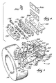
- FIG. 1 illustrates a suspension system 10 embodying the invention.
- the suspension system 10 is preferably for use with small, lightweight-utility, low-speed, turf, and three-wheeled vehicles (not shown). Such vehicles can include small compact cars, small off-road utility trucks, neighborhood vehicles typically used in retirement communities, golf carts, and the like.
- the suspension system 10 can be used in conjunction with driven or non-driven wheels and is preferably used in conjunction with the non-steering wheels.
- the suspension system 10 incorporates two substantially identical independent suspension assemblies 14, one for a driver or left-side wheel 18, and one for a passenger or right-side wheel 22.
- the term "wheel” is meant to include both a tire supporting member or rim on its own, and the combination of a tire supporting member with a mounted tire.
- the vehicle includes a frame or body portion generally indicated as 26.
- frame and “body portion” are used interchangeably in recognition that many smaller, inexpensive vehicles do not include a frame structure that is distinct from the body of the vehicle.
- body portion includes any portion of the vehicle capable of supporting a portion of the suspension system 10 and the respective loads and forces associated therewith.
- the body portion 26 includes left and right substantially horizontal support members 30 and 34, respectively.
- the support members 30 and 34 are preferably I-beams made of aluminum, steel, iron or any other suitable material.
- the support members 30 and 34 include (see Fig. 3) respective top surfaces 38 and bottom surfaces 42.
- the body portion 26 further includes (see Fig. 1) left and right angled support members 46 and 50.
- the angled support members 46 and 50 are preferably tubular and are made from aluminum, steel, iron or any other suitable material.
- the angled support members 46 and 50 are mounted to the top surfaces 38 of the respective horizontal support members 30 and 34 in any suitable manner, such as by welding or any other mechanical fastening methods.
- Each angled support member 46 and 50 includes a mounting bracket 54 integral with, or fixed thereto.
- Each mounting bracket 54 includes a connection end 58, the purpose of which will be described below. It should be understood that the specific configuration of the frame or body portion 26 is not critical to the invention, but rather may vary considerably from vehicle to vehicle.
- a power source 62 (see Fig. 1) is supported between the support members 30 and 34 and is capable of driving the wheels 18 and 22.
- the power source 62 can be a gasoline engine, a battery-powered electric motor, or any other suitable power source.
- the power source 62 has an integral continuously variable transmission or CVT and transaxle (i.e., a gear box and differential). It should be noted that the power source 62 can be located elsewhere on the vehicle, including at the front of the vehicle.
- a transaxle output shaft 66 extends from the power source 62 in opposite directions toward both the wheels 18 and 22.
- Left and right brake assemblies 70 and 74 surround the transaxle output shaft 66 on opposite sides of the power source 62.
- the brake assemblies 70 and 74 are preferably mounted in the inboard location illustrated in Fig. 1.
- the terms “inner” and “inboard” refer generally to the central portion of vehicle and a direction extending from either of the wheels 18 and 22 towards the power source 62, while “outer” and “outboard” refer generally to the opposing outside portions of the vehicle and a direction extending from the power source 62 towards either of the wheels 18 and 22.
- the brake assemblies 70 and 74 are part of the vehicle's sprung mass, meaning that they are supported by the suspension system 10. This arrangement is preferable to mounting the brake assemblies 70 and 74 adjacent the wheels 18 and 22, wherein the brake assemblies 70 and 74 would be part of the vehicle's unsprung mass. To reduce the transmission of vibration forces to the body portion 26, it is desirable to minimize the un-sprung mass of a vehicle.
- the invention could be practiced, however, with the brake assemblies 70 and 74 mounted adjacent the wheels 18 and 22 as discussed below.
- the brake assemblies 70 and 74 are conventional disk brake assemblies with cast iron disks and hydraulically or mechanically actuated calipers.
- the independent suspension assemblies 14 of the suspension system 10 are substantially mirror images of one another and only one independent suspension assembly 14 will be described in detail. Like reference numerals indicate like parts. Referring to Figs. 1-3, the right-side or passenger-side independent suspension assembly 14 is mounted between the wheel 22 and the support members 34 and 50.
- the wheel 22 is mounted on a wheel support member or hub assembly 78 having an inner hub member 82 and an outer hub member 86 (see Fig. 1).
- the outer hub member 86 is rotatably supported by the inner hub member 82 and is connected to the wheel 22.
- the inner hub member 82 includes a hollow central portion 90, a lower support flange 94, and an upper support flange 98.
- the inner hub member 82 is preferably a cast or forged metallic part.
- the lower support flange 94 includes spaced-apart sidewalls 102 having aligned apertures extending therethrough for receiving a pivot pin 106.
- the pivot pin 106 defines a lower pivot point having a pivot axis 110 (see Figs. 2, 5, and 7-8).
- the upper support flange 98 also includes spaced-apart sidewalls 114 having aligned apertures extending therethrough for receiving a pivot pin 118.
- the pivot pin 118 defines an upper pivot point having a pivot axis 122 (see Fig. 2).
- a first or lower control arm 126 is pivotally connected between the hub assembly 78 and the support member 34.
- the lower control arm 126 includes an outboard end 130, an inboard end 134 having spaced-apart arms 136, and a generally wishbone-shaped body portion 138 extending between the outboard end 130 and the inboard end 134.
- the lower control arm 126 is preferably an aluminum casting, but can also be cast or fabricated from other materials, such as steel or iron. As will be explained in greater detail below, the lower control arm 126 is a relatively simple part and need not be a complex and/or reinforced stamped or forged part like those typical of the prior art.
- the outboard end 130 of the lower control arm 126 is pivotally connected to the lower flange 94 of the inner hub member 82 via the pivot pin 106.
- the outboard end 130 includes (see Figs. 2, 5, and 7-8) a generally cylindrical mounting tube 142 that fits between spaced-apart sidewalls 102 to receive the pivot pin 106.
- An elastomeric bushing 146 (see Figs. 5 and 7-8) is positioned between the pivot pin 106 and the cylindrical mounting tube 142 to isolate the pivot pin 106 from the lower control arm 126.
- the bushing 146 eliminates the need for lubricating an otherwise metal-on-metal connection and helps prevent high-frequency vibration from being transmitted into the lower control arm 126.
- the bushing 146 like the other bushings yet to be described, is preferred, but is not required.
- the inboard end 134 of the lower control arm 126 is pivotally connected to the support member 34.
- an L-shaped mounting bracket 150 is preferably welded or otherwise attached to the bottom surface 42 of the support member 34.
- a connection plate 154 is fastened to the L-shaped mounting bracket 150 with fasteners 158.
- the connection plate 154 preferably includes two spaced-apart supports 162 and 166, respectively.
- Each of the spaced-apart supports 162 and 166 includes a pair of spaced-apart sidewalls 170 (see Fig. 4) with aligned apertures extending therethrough for receiving a pivot pin 174.
- the pivot pins 174 define two pivot points that share a common pivot axis 178 (see Figs. 5 and 7-8).
- Each of the spaced-apart arms 136 of the inboard end 134 includes a generally cylindrical mounting tube 182 that fits between the respective spaced-apart sidewalls 170 to receive the respective pivot pin 174.
- Elastomeric bushings 186 are positioned between the pivot pins 174 and the cylindrical mounting tubes 182 to isolate the pivot pins 174 from the lower control arm 126.
- a second or upper control arm 190 (see Figs. 1-3 and 6) is also pivotally connected between the hub assembly 78 and the support member 34.
- the upper control arm 190 includes an outboard end 194, an inboard end 198, and a rod 202 extending between the outboard end 194 and the inboard end 198.
- the upper control arm 190 preferably includes an adjustment mechanism capable of adjusting the overall length of the upper control arm 190. This adjustability provides for a wider range of camber alignment adjustments, as will be further described below.
- the rod 202 includes external threads while the outboard and inboard ends 194 and 198 include threaded bores that receive the opposite ends of the threaded rod 202. By turning the rod 202 relative to the outboard and inboard ends 194 and 198, the overall length of the upper control arm 190 can be adjusted.
- This type of upper control arm 190 is known in the industry and will not be described in greater detail.
- the outboard end 194 of the upper control arm 190 is pivotally connected to the upper flange 98 of the inner hub member 82 via the pivot pin 118.
- the outboard end 194 includes a generally cylindrical mounting tube 206 (see Fig. 3) that fits between spaced-apart sidewalls 114 to receive the pivot pin 118.
- An elastomeric bushing (not shown) similar to bushing 146 is positioned between the pivot pin 118 and the cylindrical mounting tube 206 to isolate the pivot pin 118 from the upper control arm 190.
- the inboard end 198 of the upper control arm 190 is pivotally connected to the support member 34.
- a connecting bracket 210 is preferably welded or otherwise attached to the top surface 38 of the support member 34.
- the connecting bracket 210 includes a pair of spaced-apart sidewalls 214 (see Fig. 3) with aligned apertures extending therethrough for receiving a pivot pin 218.
- the inboard end 134 of the upper control arm 190 includes a generally cylindrical mounting tube 226 (see Fig. 3) that fits between the spaced-apart sidewalls 214 to receive the pivot pin 218.
- An elastomeric bushing (not shown), similar to the bushings 186, is positioned between the pivot pin 218 and the cylindrical mounting tube 226 to isolate the pivot pin 218 from the upper control arm 190.
- the independent suspension assembly 14 further includes a strut 228 pivotally connected between the hub assembly 78 and the angled support member 50.
- the strut 228 includes a shock absorbing member 230 and a spring 234 mounted substantially coaxially with the shock absorbing member 230 as is well-known.
- the strut 228 has (see Fig. 6) an outboard end 238 and an inboard end 242.
- the outboard end 238 of the strut 228 is pivotally connected to the lower flange 94 of the inner hub member 82 via the pivot pin 106.
- the outboard end 238 includes (see Figs. 5 and 7-8) a generally cylindrical mounting tube 242 that is positioned rearwardly of the spaced-apart sidewalls 102 to receive the pivot pin 106.
- the generally cylindrical mounting tube 242 When mounted on the pivot pin 106, the generally cylindrical mounting tube 242 is adjacent the rearward-most sidewall 102.
- An elastomeric bushing 246 is positioned between the pivot pin 106 and the cylindrical mounting tube 242 to isolate the pivot pin 106 from the strut 228. The bushing 246 can also isolate the strut 228 from the rearward-most sidewall 102.
- outboard end 238 of the strut 228 is shown positioned rearwardly of the outboard end 130 of the lower control arm 126, it is also possible to reverse the orientation of the outboard ends 130 and 238 such that the outboard end 130 is positioned rearwardly of the outboard end 238.
- the important aspect is that the outboard end 130 of the lower control arm 126 and the outboard end 238 of the strut 228 are both pivotally connected to the hub assembly 78 at the same pivot point (i.e., by pivot pin 106), and both pivot about the pivot axis 110. The importance of this common pivot point arrangement will be discussed in greater detail below.
- the inboard end 242 of the strut 228 is pivotally connected to the angled support member 50 at the connection end 58 of the mounting bracket 54.
- the connection end 58 includes a pair of spaced-apart sidewalls 250 (only one is shown in Figs. 1 and 6) with aligned apertures extending therethrough for receiving a pivot pin 254.
- the inboard end 242 of the strut 228 includes a generally cylindrical mounting tube (not shown) that fits between the spaced-apart sidewalls 250 to receive the pivot pin 254.
- An elastomeric bushing (not shown) similar to the bushing 186 is positioned between the pivot pin 254 and the cylindrical mounting tube of the inboard end 242 to isolate the pivot pin 254 from the strut 228.
- the vehicle also includes a drive shaft 258 connected between the transaxle output shaft 66 and the outer hub member 86.
- the drive shaft 258 transfers rotational power from the transaxle output shaft 66 to the wheel 22 as is commonly understood.
- the suspension system 10 can be used for non-driven wheels as well as for driven wheels.
- the drive shaft 258 is eliminated.
- the drive shaft 258 is an adjustable, articulating drive shaft available from GKN Drivetech, Inc. in Walled Lake, Michigan. As best seen in Figs. 9-11, the drive shaft 258 includes an outboard end 262, an inboard end 266, and a central shaft portion 270 extending between the outboard and inboard ends 262 and 266.
- the outboard end 262 includes a splined portion 274 that is connected to the outer hub portion 86 to cause the rotation of the outer hub portion 86, thereby rotating the wheel 22.
- Adjacent the splined portion 274 is a ball-and-socket-type articulation joint 278 capable of articulating to accommodate a range of wheel positions corresponding to the jouncing and rebounding of the wheel.
- the articulation joint 278 is protected from contamination by a resilient boot (not shown).
- the inboard end 266 includes a splined transaxle receiving bore 286 that receives a splined end of the transaxle output shaft 66, thereby transmitting the rotation of the transaxle output shaft 66 into the driveshaft 258.
- the receiving bore 286 is retained axially to the transaxle output shaft 66 with an internal ring and groove arrangement.
- Adjacent the transaxle receiving bore 286 is a traveling articulation joint 290.
- the traveling articulation joint 290 is capable of both articulating in a manner similar to the articulation joint 278, and moving between an axially retracted position (see Fig. 10) and an axially extended position (see Fig. 11). The range of extension accommodates the changing distances between the wheel 22 and the end of the transaxle output shaft 66 during the jouncing and rebounding of the wheel 22.
- the traveling articulation joint 290 is also protected from contamination by a resilient boot (not shown).
- the suspension system 10 also includes an inexpensive method for adjusting the orientation or alignment of the wheels 18 and 22.
- Fig. 4 illustrates a plurality of different shims or shim pieces 300 that can be selectively installed between the inboard end 130 of lower control arm 126 and the support member 34 to achieve a desired offset between the hub assembly 78 and the support member 34.
- the shim pieces 300 can be made of any suitable material, such as steel, stainless steel, aluminum, brass, or any other corrosion-resistant material.
- the shim pieces 300 are preferably individually and/or cumulatively installed between the L-shaped mounting bracket 150 and the connection plate 154 to achieve the desired offset between the hub assembly 78 and the support members 30 and 34, thereby providing an inexpensive way of adjusting the wheel alignment.
- the desired offset can be achieved using any single or multiple shim arrangement.
- a single shim piece 300 can be used to achieve the desired offset, or alternatively, two or more shim pieces 300 can be positioned between the L-shaped mounting bracket 150 and the connection plate 154 in stacked relation and/or in side-by-side relation.
- the shim pieces 300 can have various lengths, and thicknesses.
- the length of the shim pieces 300 can be substantially the same as the length of the connection plate 154, in which case the shim pieces 300 will preferably include the same number of holes or apertures as the connection plate 154, for receiving the fasteners 158.
- the shim pieces 300 can have substantially shorter lengths than the connection plate 154, in which case the shim pieces 300 may include fewer holes than the connection plate 154, and only receive a fraction of the fasteners 158.
- the thicknesses of the shim pieces 300 can be uniform, to yield a generally rectangularly-shaped shim, variable, to yield a generally wedge-shaped shim, or any combination of uniform and variable.
- the thickness of the individual shim pieces 300 will range from approximately 0.5 mm to 3 mm.
- the wheels 18 and 22 can undergo various alignment or orientation adjustments.
- the terms “alignment” and “orientation” are meant to broadly describe the positioning of the wheel with respect to the body portion 26.
- Figs. 5 and 6 illustrate a first alignment adjustment that can be made using the shims 300.
- This first alignment adjustment is known to those skilled in the art as adjusting the camber of the wheel.
- the wheels 18 and 22 have an upper end 304 spaced a distance from the vehicle body 26 and a lower end 308 spaced a distance from the vehicle body 26.
- the orientation of the wheel's vertical axis with respect to the vehicle body 26 (as shown in Fig. 5) can be changed.
- a shim 300 is positioned between the L-shaped mounting bracket 150 and the connection plate 154.
- the shim 300 increases the offset between the lower flange 94 of the hub assembly 78.
- the camber of the wheels 18 and 22 are adjusted from a first wheel orientation (shown in phantom in Figs. 5 and 6), wherein no shim 300 is used, to a second or adjusted wheel orientation, wherein the presence of the shim 300 causes the distance between the upper end 304 of the wheels 18 and 22 and the respective support members 30 and 34 to decrease, and causes the distance between the lower end 308 of the wheels 18 and 22 and the respective support members 30 and 34 to increase.
- the camber of the wheels 18 and 22 can be adjusted to a wide range of desired wheel orientations.
- the adjustable upper control arm 190 also helps enable a wide range of camber adjustments to take place.
- Figs. 7 and 8 illustrate a second type of alignment adjustment that can be made using the shims 300.
- This second alignment adjustment is known to those skilled in the art as adjusting the toe position or toe-in/out orientation of the wheel.
- the wheel 22 has a toe or forward end 312 spaced a distance from the vehicle body 26 and a heel or rearward end 316 spaced a distance from the vehicle body 26.
- the orientation of the wheel's horizontal axis with respect to the vehicle body 26 (as shown in Figs. 7 and 8) can be changed.
- a shim 300 is positioned between the L-shaped mounting bracket 150 and the connection plate 154.
- the shim 300 in Fig. 7 is shown as being substantially wedge-shaped with the thicker portion adjacent the support 166 and the thinner portion adjacent the support 162. It should be noted, however, that a similar outcome could be achieved using a plurality of shorter length shims having different thicknesses placed in side-by-side relation, a plurality of selectively stacked shorter length shims, or a single shorter length shim mounted between the support 166 and the L-shaped mounting bracket 150 with no shim mounted between the support 162 and the L-shaped mounting bracket 150.
- the shim 300 changes the orientation of the pivot axis 178 and thus changes the offset between the hub assembly 78 and the body portion 26 to adjust the wheel alignment.
- the toe 312 of the wheel 22 is adjusted from a first wheel orientation (shown in phantom in Fig. 7), wherein no shim 300 is used, to a second or toe-out adjusted wheel orientation, wherein the presence of the shim 300 causes the distance between the toe 312 and the support member 34 to increase.
- Fig. 8 illustrates the use of a shim 300 to adjust the wheel 22 from a first wheel orientation (shown in phantom in Fig. 8), wherein no shim 300 is used, to a second or toe-in adjusted wheel orientation, wherein the presence of the shim 300 causes the distance between the toe 312 and the support member 34 to decrease.
- the shim 300 in Fig. 8 is also wedge-shaped, however, the thicker portion of the shim 300 is adjacent the support 162 while the thinner portion of the shim 300 is adjacent the support 166.
- the wheel camber orientation can also change somewhat, but such a change to the camber orientation can be minimized by changing the configuration of the shim pieces 300 and/or adjusting the length of the upper control arm 190 as appropriate.
- the wheel's first or pre-adjustment orientation with respect to the vehicle body 26 must be determined. This can be done using any known mechanical or optical wheel alignment devices (not shown) or any other method including basic drive testing or visual inspection techniques.
- an analysis can be performed to determine whether the first wheel orientation is proper, or whether the wheel is improperly oriented and an alignment adjustment is needed. This analysis can be computer assisted, in the case of some of the more complex alignment devices, or can be manually determined. If it is determined that an adjustment is needed, the analysis includes determining what type of alignment adjustment (i.e., camber, toe position, or both) is needed and how much of an adjustment is needed.
- the adjustment can include inserting additional shim pieces 300, removing shim pieces 300, changing the configuration of shim pieces 300, or any combination of these actions as described above.
- the adjustment can also include adjusting the length of the upper control arm 190 as described above.
- the vehicle can be manufactured such that the first wheel orientation is achieved using one or more shim pieces 300 that are stacked between the L-shaped mounting bracket 150 and the support 162 on the connection plate 154. Likewise one or more shim pieces 300 can be stacked between the L-shaped mounting bracket 150 and the support 166 on the connection plate 154. Instead of just adding or removing a shim 300 with the necessary thickness to achieve the desired toe adjustment, the technician can add one half of the necessary shim thickness at one end of the connection plate 154 and remove one half of the necessary shim thickness at the other end of the connection plate 154.
- the technician can remove one or more shim pieces 300 from between the support 162 and the connection plate 154, and can add the same number of shim pieces 300, having the same net thickness, between the support 166 and the connection plate 154.
- the effect of such an adjustment will be to create a second wheel orientation that has an increased toe-out orientation but the same camber orientation as compared to the first wheel orientation.
- the technician removes one or more shim pieces 300 from between the support 166 and the connection plate 154 and adds the same number of shim pieces 300, having the same net thickness, between the support 162 and the connection plate 154.
- the outboard end 238 of the strut 228 and the outboard end 130 of the lower control arm 126 are both pivotally mounted to the hub assembly 78 at a common pivot point.
- This is different than prior art suspension systems (e.g., double wishbone or short-long arm design) in which the strut is mounted directly to the lower control arm. Mounting the strut directly to the lower control arm imparts large bending stresses into the lower control arm. In order to tolerate these bending stresses, prior art lower control arms must be designed for added strength and rigidity and are usually heavy and complex stamped or forged parts.
- the common pivot point arrangement of the present invention minimizes the bending stresses that are normally created in the lower control arm 126 by the strut 228. Substantially all of the axial force in the strut 228 is transmitted directly into the lower flange 94 of the inner hub member 82. Since the lower control arm 126 is not subjected to most of the axial forces in the strut 228, the lower control arm 126 need not have the strength and rigidity required in prior art suspension systems.
- the design of the present invention also minimizes the torsional forces normally imparted on the lower control arm when the brakes are mounted outboard of the control arms, adjacent the wheels.
- the lower control arm 126 can have a simple, light-weight, and inexpensive design.
- the lower control arm 126 is preferably a simple, wishbone-shaped, cast part.
- Prior art suspension systems also often utilize an upper control arm that is similar to the complex stamped or forged lower control arm.
- the upper control arms of prior art suspension systems must also be strong enough to bear the substantial torsional brake reaction forces generated when the brakes are mounted adjacent the wheels.
- the strut usually passes through the upper control arm, making the design even more complex. Because the suspension system 10 of the present invention is used with smaller, low-speed vehicles, and the brake assemblies 70 and 74 are positioned inboard of the upper and lower control arms 190 and 126, the upper control arm 190 can be a much smaller rod-type linkage as shown. This further reduces the weight, expense, and size of the suspension system 10.
- the suspension system 10 of the present invention provides excellent ride and handling characteristics, while retaining excellent braking performance, for smaller vehicles by reducing the vehicle's un-sprung mass without sacrificing key suspension components.
- the space needed for the suspension system 10 is also reduced.
- the cost of the suspension system 10 is kept low due to the elimination of complex, and expensive to manufacture control arms.
- the suspension system 10 of the present invention could also be used with brake assemblies mounted outboard, adjacent the wheels 18 and 22. If this were the case, however, it may be necessary to increase the strength and/or rigidity of the lower control arm 126, the upper control arm 190, or both. Likewise, the suspension system 10 of the present invention could be adapted for use on larger, heavier, and higher-speed vehicles, but would likely require stronger and more rigid control arms.
Landscapes
- Engineering & Computer Science (AREA)
- Mechanical Engineering (AREA)
- Vehicle Body Suspensions (AREA)
Abstract
Description
- The invention relates to powered vehicles, and more particularly to suspension systems for powered vehicles.
- Suspension systems are commonly used on modem powered vehicles to isolate the wheels of the vehicle from the frame or body of the vehicle and thus from the passenger compartment. External forces acting on the wheels, due to irregularities in the driving surface or vehicle maneuvering, are absorbed by the suspension system to reduce or substantially eliminate the transmission of these forces into the frame. The suspension systems are designed to provide the desired ride and handling characteristics by varying the spring forces and the amount of absorption that occurs.
- There are many different types of suspension systems, each having different absorption characteristics, advantages, and disadvantages. Several factors influence the type of suspension system that can be used in a particular vehicle.
- One important factor is the size and shape of the envelope in which the suspension system must be located. Another important factor is the size of the vehicle and the type of usage and loading that the vehicle will experience. The speed at which the vehicle will operate is yet another important factor in selecting and designing an appropriate suspension system. Additionally, the cost of the vehicle also plays a role in determining what type of suspension system is used.
- The present invention provides an improved vehicle suspension system for use with small, lightweight-utility, low-speed, turf, and three-wheeled vehicles. Such vehicles include small compact cars, small off-road utility trucks, neighborhood vehicles typically used in retirement communities, golf carts, and the like. The suspension system of the present invention is extremely versatile, and thereby capable of handling the broad range of operating conditions normally encountered by each of the above-mentioned vehicles. Additionally, the overall cost of the vehicle is kept low because the suspension system is relatively inexpensive to manufacture and assemble.
- More specifically, the invention provides a vehicle suspension system including a vehicle body and a hub assembly spaced from the vehicle body and having an inner hub member. The suspension system further includes a first control arm having an outboard end pivotally connected to the inner hub member at a first pivot point having a first pivot axis, and an inboard end pivotally connected to the vehicle body. Additionally, the suspension system has a strut including a shock absorbing member and a spring mounted substantially coaxially with the shock absorbing member. The strut has an outboard end pivotally connected to the inner hub member at the first pivot point such that the first control arm and the strut both pivot about the first pivot axis. The strut also has an inboard end pivotally connected to the vehicle body.
- In one aspect of the invention, the suspension system includes a second control arm having an outboard end pivotally connected to the inner hub member at a second pivot point having a second pivot axis, and an inboard end pivotally connected to the vehicle body. Preferably, the second control arm is an adjustable rod.
- In another aspect of the invention, a shim is positioned between the inboard end of the control arm and the vehicle body to achieve a desired offset between the hub assembly and the vehicle body.
- Furthermore, the invention provides a method of adjusting the alignment of a wheel of a vehicle with respect to a vehicle body. The wheel is connected to the vehicle body by a control arm having an inboard end interconnected with the vehicle body. The method includes determining a first wheel orientation with respect to the vehicle body, analyzing the first wheel orientation to determine whether the wheel is properly oriented with respect to the vehicle body, and changing a spacing between the inboard end of the control arm and the vehicle body using a shim when the wheel is not properly oriented with respect to the vehicle body, such that the first wheel orientation is adjusted to a second wheel orientation with respect to the vehicle body. Changing the spacing using the shim preferably includes inserting a shim and/or removing a shim, or changing the configuration of the shim between the inboard end and the vehicle body.
- Other features and advantages of the invention will become apparent to those skilled in the art upon review of the following detailed description, claims, and drawings.
-
- Fig. 1 is a rear view of a suspension system embodying the invention.
- Fig. 2 is a perspective view showing a portion of the passenger or right side of the suspension system of Fig. 1, with parts removed for ease of illustration.
- Fig. 3 is another perspective view of the passenger side of the suspension system of Fig. 1.
- Fig. 4 is an exploded view showing a portion of the mounting assembly of the suspension system of Fig. 1.
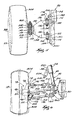
- Fig. 5 is a top view, partially cut away, illustrating an alignment adjustment to the passenger side of the suspension system of Fig. 1, with parts removed for ease of illustration.
- Fig. 6 is a rear view of the driver or left side of the suspension system having a similar alignment adjustment to that shown in Fig. 5, with parts removed for ease of illustration.
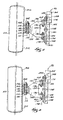
- Fig. 7 is a top view, partially cut away, illustrating another alignment adjustment to the passenger side of the suspension system of Fig. 1, with parts removed for ease of illustration.
- Fig. 8 is a top view, partially cut away, illustrating yet another alignment adjustment to the passenger side of the suspension system of Fig. 1, with parts removed for ease of illustration.
- Fig. 9 is a plan view, partially cut away, showing the drive shaft used with the suspension system embodying the invention.
- Fig. 10 is an enlarged section view showing a portion of the drive shaft of Fig. 9 in a retracted position.
- Fig. 11 is an enlarged section view showing a portion of the drive shaft of Fig. 9 in an extended position.
-
- Before one embodiment of the invention is explained in detail, it is to be understood that the invention is not limited in its application to the details of construction and the arrangements of the components set forth in the following description or illustrated in the drawings. The invention is capable of other embodiments and of being practiced or being carried out in various ways. Also, it is understood that the phraseology and terminology used herein is for the purpose of description and should not be regarded as limiting. The use of "including" and "comprising" and variations thereof herein is meant to encompass the items listed thereafter and equivalents thereof as well as additional items.
- Figure 1 illustrates a
suspension system 10 embodying the invention. Thesuspension system 10 is preferably for use with small, lightweight-utility, low-speed, turf, and three-wheeled vehicles (not shown). Such vehicles can include small compact cars, small off-road utility trucks, neighborhood vehicles typically used in retirement communities, golf carts, and the like. Thesuspension system 10 can be used in conjunction with driven or non-driven wheels and is preferably used in conjunction with the non-steering wheels. Thesuspension system 10 incorporates two substantially identicalindependent suspension assemblies 14, one for a driver or left-side wheel 18, and one for a passenger or right-side wheel 22. As used herein and in the appended claims, the term "wheel" is meant to include both a tire supporting member or rim on its own, and the combination of a tire supporting member with a mounted tire. - As shown in Fig. 1, the vehicle includes a frame or body portion generally indicated as 26. It should be noted that the terms "frame" and "body portion" are used interchangeably in recognition that many smaller, inexpensive vehicles do not include a frame structure that is distinct from the body of the vehicle. As used herein and in the appended claims, the term "body portion" includes any portion of the vehicle capable of supporting a portion of the
suspension system 10 and the respective loads and forces associated therewith. - As best seen in Figs. 1 and 3, the
body portion 26 includes left and right substantiallyhorizontal support members support members support members top surfaces 38 andbottom surfaces 42. Thebody portion 26 further includes (see Fig. 1) left and rightangled support members 46 and 50. Theangled support members 46 and 50 are preferably tubular and are made from aluminum, steel, iron or any other suitable material. Theangled support members 46 and 50 are mounted to thetop surfaces 38 of the respectivehorizontal support members angled support member 46 and 50 includes amounting bracket 54 integral with, or fixed thereto. Eachmounting bracket 54 includes aconnection end 58, the purpose of which will be described below. It should be understood that the specific configuration of the frame orbody portion 26 is not critical to the invention, but rather may vary considerably from vehicle to vehicle. - A power source 62 (see Fig. 1) is supported between the
support members wheels power source 62 can be a gasoline engine, a battery-powered electric motor, or any other suitable power source. In the preferred embodiment, thepower source 62 has an integral continuously variable transmission or CVT and transaxle (i.e., a gear box and differential). It should be noted that thepower source 62 can be located elsewhere on the vehicle, including at the front of the vehicle. As seen in Fig. 3, atransaxle output shaft 66 extends from thepower source 62 in opposite directions toward both thewheels right brake assemblies 70 and 74 (see Fig. 1) surround thetransaxle output shaft 66 on opposite sides of thepower source 62. Thebrake assemblies wheels power source 62, while "outer" and "outboard" refer generally to the opposing outside portions of the vehicle and a direction extending from thepower source 62 towards either of thewheels - By mounting the
brake assemblies power source 62, thebrake assemblies suspension system 10. This arrangement is preferable to mounting thebrake assemblies wheels brake assemblies body portion 26, it is desirable to minimize the un-sprung mass of a vehicle. The invention could be practiced, however, with thebrake assemblies wheels brake assemblies - The
independent suspension assemblies 14 of thesuspension system 10 are substantially mirror images of one another and only oneindependent suspension assembly 14 will be described in detail. Like reference numerals indicate like parts. Referring to Figs. 1-3, the right-side or passenger-sideindependent suspension assembly 14 is mounted between thewheel 22 and thesupport members 34 and 50. Thewheel 22 is mounted on a wheel support member orhub assembly 78 having aninner hub member 82 and an outer hub member 86 (see Fig. 1). The outer hub member 86 is rotatably supported by theinner hub member 82 and is connected to thewheel 22. Theinner hub member 82 includes a hollowcentral portion 90, alower support flange 94, and anupper support flange 98. Theinner hub member 82 is preferably a cast or forged metallic part. - The
lower support flange 94 includes spaced-apartsidewalls 102 having aligned apertures extending therethrough for receiving apivot pin 106. As will be described in more detail below, thepivot pin 106 defines a lower pivot point having a pivot axis 110 (see Figs. 2, 5, and 7-8). Theupper support flange 98 also includes spaced-apartsidewalls 114 having aligned apertures extending therethrough for receiving apivot pin 118. Thepivot pin 118 defines an upper pivot point having a pivot axis 122 (see Fig. 2). - A first or
lower control arm 126 is pivotally connected between thehub assembly 78 and thesupport member 34. Thelower control arm 126 includes anoutboard end 130, aninboard end 134 having spaced-apartarms 136, and a generally wishbone-shapedbody portion 138 extending between theoutboard end 130 and theinboard end 134. Thelower control arm 126 is preferably an aluminum casting, but can also be cast or fabricated from other materials, such as steel or iron. As will be explained in greater detail below, thelower control arm 126 is a relatively simple part and need not be a complex and/or reinforced stamped or forged part like those typical of the prior art. - The
outboard end 130 of thelower control arm 126 is pivotally connected to thelower flange 94 of theinner hub member 82 via thepivot pin 106. Theoutboard end 130 includes (see Figs. 2, 5, and 7-8) a generally cylindrical mountingtube 142 that fits between spaced-apartsidewalls 102 to receive thepivot pin 106. An elastomeric bushing 146 (see Figs. 5 and 7-8) is positioned between thepivot pin 106 and the cylindrical mountingtube 142 to isolate thepivot pin 106 from thelower control arm 126. Thebushing 146 eliminates the need for lubricating an otherwise metal-on-metal connection and helps prevent high-frequency vibration from being transmitted into thelower control arm 126. Thebushing 146, like the other bushings yet to be described, is preferred, but is not required. - The
inboard end 134 of thelower control arm 126 is pivotally connected to thesupport member 34. As best seen in Figs. 1 and 3-4, an L-shapedmounting bracket 150 is preferably welded or otherwise attached to thebottom surface 42 of thesupport member 34. Aconnection plate 154 is fastened to the L-shapedmounting bracket 150 withfasteners 158. Theconnection plate 154 preferably includes two spaced-apart supports 162 and 166, respectively. Each of the spaced-apart supports 162 and 166 includes a pair of spaced-apart sidewalls 170 (see Fig. 4) with aligned apertures extending therethrough for receiving apivot pin 174. Together, the pivot pins 174 define two pivot points that share a common pivot axis 178 (see Figs. 5 and 7-8). - Each of the spaced-apart
arms 136 of theinboard end 134 includes a generally cylindrical mountingtube 182 that fits between the respective spaced-apartsidewalls 170 to receive therespective pivot pin 174. Elastomeric bushings 186 (see Fig. 4) are positioned between the pivot pins 174 and the cylindrical mountingtubes 182 to isolate the pivot pins 174 from thelower control arm 126. - A second or upper control arm 190 (see Figs. 1-3 and 6) is also pivotally connected between the
hub assembly 78 and thesupport member 34. Theupper control arm 190 includes anoutboard end 194, an inboard end 198, and arod 202 extending between theoutboard end 194 and the inboard end 198. Theupper control arm 190 preferably includes an adjustment mechanism capable of adjusting the overall length of theupper control arm 190. This adjustability provides for a wider range of camber alignment adjustments, as will be further described below. In the illustrated embodiment, therod 202 includes external threads while the outboard and inboard ends 194 and 198 include threaded bores that receive the opposite ends of the threadedrod 202. By turning therod 202 relative to the outboard and inboard ends 194 and 198, the overall length of theupper control arm 190 can be adjusted. This type ofupper control arm 190 is known in the industry and will not be described in greater detail. - The
outboard end 194 of theupper control arm 190 is pivotally connected to theupper flange 98 of theinner hub member 82 via thepivot pin 118. Theoutboard end 194 includes a generally cylindrical mounting tube 206 (see Fig. 3) that fits between spaced-apartsidewalls 114 to receive thepivot pin 118. An elastomeric bushing (not shown) similar tobushing 146 is positioned between thepivot pin 118 and the cylindrical mountingtube 206 to isolate thepivot pin 118 from theupper control arm 190. - The inboard end 198 of the
upper control arm 190 is pivotally connected to thesupport member 34. As seen in Figs. 1, 3 and 6, a connectingbracket 210 is preferably welded or otherwise attached to thetop surface 38 of thesupport member 34. The connectingbracket 210 includes a pair of spaced-apart sidewalls 214 (see Fig. 3) with aligned apertures extending therethrough for receiving apivot pin 218. - The
inboard end 134 of theupper control arm 190 includes a generally cylindrical mounting tube 226 (see Fig. 3) that fits between the spaced-apartsidewalls 214 to receive thepivot pin 218. An elastomeric bushing (not shown), similar to thebushings 186, is positioned between thepivot pin 218 and the cylindrical mountingtube 226 to isolate thepivot pin 218 from theupper control arm 190. - The
independent suspension assembly 14 further includes astrut 228 pivotally connected between thehub assembly 78 and the angled support member 50. Thestrut 228 includes ashock absorbing member 230 and aspring 234 mounted substantially coaxially with theshock absorbing member 230 as is well-known. Thestrut 228 has (see Fig. 6) anoutboard end 238 and aninboard end 242. - As best seen in Figs. 2 and 5-8, the
outboard end 238 of thestrut 228 is pivotally connected to thelower flange 94 of theinner hub member 82 via thepivot pin 106. Theoutboard end 238 includes (see Figs. 5 and 7-8) a generally cylindrical mountingtube 242 that is positioned rearwardly of the spaced-apartsidewalls 102 to receive thepivot pin 106. When mounted on thepivot pin 106, the generally cylindrical mountingtube 242 is adjacent therearward-most sidewall 102. Anelastomeric bushing 246 is positioned between thepivot pin 106 and the cylindrical mountingtube 242 to isolate thepivot pin 106 from thestrut 228. Thebushing 246 can also isolate thestrut 228 from therearward-most sidewall 102. - While the
outboard end 238 of thestrut 228 is shown positioned rearwardly of theoutboard end 130 of thelower control arm 126, it is also possible to reverse the orientation of the outboard ends 130 and 238 such that theoutboard end 130 is positioned rearwardly of theoutboard end 238. The important aspect is that theoutboard end 130 of thelower control arm 126 and theoutboard end 238 of thestrut 228 are both pivotally connected to thehub assembly 78 at the same pivot point (i.e., by pivot pin 106), and both pivot about thepivot axis 110. The importance of this common pivot point arrangement will be discussed in greater detail below. - The
inboard end 242 of thestrut 228 is pivotally connected to the angled support member 50 at the connection end 58 of the mountingbracket 54. Theconnection end 58 includes a pair of spaced-apart sidewalls 250 (only one is shown in Figs. 1 and 6) with aligned apertures extending therethrough for receiving apivot pin 254. Theinboard end 242 of thestrut 228 includes a generally cylindrical mounting tube (not shown) that fits between the spaced-apartsidewalls 250 to receive thepivot pin 254. An elastomeric bushing (not shown) similar to thebushing 186 is positioned between thepivot pin 254 and the cylindrical mounting tube of theinboard end 242 to isolate thepivot pin 254 from thestrut 228. - As seen in Figs. 1, 3, 6, and 9-11, the vehicle also includes a
drive shaft 258 connected between thetransaxle output shaft 66 and the outer hub member 86. Thedrive shaft 258 transfers rotational power from thetransaxle output shaft 66 to thewheel 22 as is commonly understood. Recall, however, that thesuspension system 10 can be used for non-driven wheels as well as for driven wheels. When used in conjunction with non-driven wheels, thedrive shaft 258 is eliminated. - The
drive shaft 258 is an adjustable, articulating drive shaft available from GKN Drivetech, Inc. in Walled Lake, Michigan. As best seen in Figs. 9-11, thedrive shaft 258 includes anoutboard end 262, aninboard end 266, and acentral shaft portion 270 extending between the outboard and inboard ends 262 and 266. Theoutboard end 262 includes asplined portion 274 that is connected to the outer hub portion 86 to cause the rotation of the outer hub portion 86, thereby rotating thewheel 22. Adjacent thesplined portion 274 is a ball-and-socket-type articulation joint 278 capable of articulating to accommodate a range of wheel positions corresponding to the jouncing and rebounding of the wheel. The articulation joint 278 is protected from contamination by a resilient boot (not shown). - The
inboard end 266 includes a splined transaxle receiving bore 286 that receives a splined end of thetransaxle output shaft 66, thereby transmitting the rotation of thetransaxle output shaft 66 into thedriveshaft 258. The receiving bore 286 is retained axially to thetransaxle output shaft 66 with an internal ring and groove arrangement. Adjacent the transaxle receiving bore 286 is a traveling articulation joint 290. The traveling articulation joint 290 is capable of both articulating in a manner similar to the articulation joint 278, and moving between an axially retracted position (see Fig. 10) and an axially extended position (see Fig. 11). The range of extension accommodates the changing distances between thewheel 22 and the end of thetransaxle output shaft 66 during the jouncing and rebounding of thewheel 22. The traveling articulation joint 290 is also protected from contamination by a resilient boot (not shown). - The
suspension system 10 also includes an inexpensive method for adjusting the orientation or alignment of thewheels shim pieces 300 that can be selectively installed between theinboard end 130 oflower control arm 126 and thesupport member 34 to achieve a desired offset between thehub assembly 78 and thesupport member 34. Theshim pieces 300 can be made of any suitable material, such as steel, stainless steel, aluminum, brass, or any other corrosion-resistant material. - More specifically, the
shim pieces 300 are preferably individually and/or cumulatively installed between the L-shapedmounting bracket 150 and theconnection plate 154 to achieve the desired offset between thehub assembly 78 and thesupport members single shim piece 300 can be used to achieve the desired offset, or alternatively, two ormore shim pieces 300 can be positioned between the L-shapedmounting bracket 150 and theconnection plate 154 in stacked relation and/or in side-by-side relation. - As illustrated in Figs. 4-8, the
shim pieces 300 can have various lengths, and thicknesses. The length of theshim pieces 300 can be substantially the same as the length of theconnection plate 154, in which case theshim pieces 300 will preferably include the same number of holes or apertures as theconnection plate 154, for receiving thefasteners 158. Alternatively, theshim pieces 300 can have substantially shorter lengths than theconnection plate 154, in which case theshim pieces 300 may include fewer holes than theconnection plate 154, and only receive a fraction of thefasteners 158. The thicknesses of theshim pieces 300 can be uniform, to yield a generally rectangularly-shaped shim, variable, to yield a generally wedge-shaped shim, or any combination of uniform and variable. Preferably, the thickness of theindividual shim pieces 300 will range from approximately 0.5 mm to 3 mm. - Depending upon the configuration of
shim pieces 300 used, thewheels body portion 26. Figs. 5 and 6 illustrate a first alignment adjustment that can be made using theshims 300. This first alignment adjustment is known to those skilled in the art as adjusting the camber of the wheel. In other words, thewheels upper end 304 spaced a distance from thevehicle body 26 and alower end 308 spaced a distance from thevehicle body 26. By changing the distances between the upper and lower ends 304 and 308 and thebody portion 26, the orientation of the wheel's vertical axis with respect to the vehicle body 26 (as shown in Fig. 5) can be changed. - As seen in Figs. 5 and 6, a
shim 300 is positioned between the L-shapedmounting bracket 150 and theconnection plate 154. Theshim 300 increases the offset between thelower flange 94 of thehub assembly 78. The camber of thewheels shim 300 is used, to a second or adjusted wheel orientation, wherein the presence of theshim 300 causes the distance between theupper end 304 of thewheels respective support members lower end 308 of thewheels respective support members shim pieces 300, or by usingshim pieces 300 of different thicknesses, the camber of thewheels upper control arm 190 also helps enable a wide range of camber adjustments to take place. - Figs. 7 and 8 illustrate a second type of alignment adjustment that can be made using the
shims 300. This second alignment adjustment is known to those skilled in the art as adjusting the toe position or toe-in/out orientation of the wheel. In other words, thewheel 22 has a toe orforward end 312 spaced a distance from thevehicle body 26 and a heel orrearward end 316 spaced a distance from thevehicle body 26. By changing the distances between the forward and rearward ends 312 and 316 and thebody portion 26, the orientation of the wheel's horizontal axis with respect to the vehicle body 26 (as shown in Figs. 7 and 8) can be changed. - As seen in Fig. 7, a
shim 300 is positioned between the L-shapedmounting bracket 150 and theconnection plate 154. Theshim 300 in Fig. 7 is shown as being substantially wedge-shaped with the thicker portion adjacent thesupport 166 and the thinner portion adjacent thesupport 162. It should be noted, however, that a similar outcome could be achieved using a plurality of shorter length shims having different thicknesses placed in side-by-side relation, a plurality of selectively stacked shorter length shims, or a single shorter length shim mounted between thesupport 166 and the L-shapedmounting bracket 150 with no shim mounted between thesupport 162 and the L-shapedmounting bracket 150. Theshim 300 changes the orientation of thepivot axis 178 and thus changes the offset between thehub assembly 78 and thebody portion 26 to adjust the wheel alignment. Thetoe 312 of thewheel 22 is adjusted from a first wheel orientation (shown in phantom in Fig. 7), wherein noshim 300 is used, to a second or toe-out adjusted wheel orientation, wherein the presence of theshim 300 causes the distance between thetoe 312 and thesupport member 34 to increase. - Fig. 8 illustrates the use of a
shim 300 to adjust thewheel 22 from a first wheel orientation (shown in phantom in Fig. 8), wherein noshim 300 is used, to a second or toe-in adjusted wheel orientation, wherein the presence of theshim 300 causes the distance between thetoe 312 and thesupport member 34 to decrease. Theshim 300 in Fig. 8 is also wedge-shaped, however, the thicker portion of theshim 300 is adjacent thesupport 162 while the thinner portion of theshim 300 is adjacent thesupport 166. By changing the configuration of theshim pieces 300, the toe-in/out orientation of thewheels wheels shim pieces 300, the wheel camber orientation can also change somewhat, but such a change to the camber orientation can be minimized by changing the configuration of theshim pieces 300 and/or adjusting the length of theupper control arm 190 as appropriate. - To adjust the alignment of a wheel, the wheel's first or pre-adjustment orientation with respect to the
vehicle body 26 must be determined. This can be done using any known mechanical or optical wheel alignment devices (not shown) or any other method including basic drive testing or visual inspection techniques. Once the first wheel orientation is known, an analysis can be performed to determine whether the first wheel orientation is proper, or whether the wheel is improperly oriented and an alignment adjustment is needed. This analysis can be computer assisted, in the case of some of the more complex alignment devices, or can be manually determined. If it is determined that an adjustment is needed, the analysis includes determining what type of alignment adjustment (i.e., camber, toe position, or both) is needed and how much of an adjustment is needed. - Next, the technician determines the appropriate way to make the adjustment with the
shim pieces 300. The adjustment can include insertingadditional shim pieces 300, removingshim pieces 300, changing the configuration ofshim pieces 300, or any combination of these actions as described above. The adjustment can also include adjusting the length of theupper control arm 190 as described above. Once the spacing between theinboard end 134 and thevehicle body 26 is changed using theshim pieces 300, and any adjustment to theupper control arm 190 has been made, the wheel is re-oriented with respect to thevehicle body 26 to a second or adjusted wheel orientation. If desired, the second wheel orientation can be checked and re-adjusted by repeating the steps outlined above. For example, if the toe position is adjusted, it may be useful to check the camber orientation and make any camber adjustments using theupper control arm 190. - It is important to point out that the toe position of the wheels can be adjusted without substantially changing the camber orientation of the wheels. The vehicle can be manufactured such that the first wheel orientation is achieved using one or
more shim pieces 300 that are stacked between the L-shapedmounting bracket 150 and thesupport 162 on theconnection plate 154. Likewise one ormore shim pieces 300 can be stacked between the L-shapedmounting bracket 150 and thesupport 166 on theconnection plate 154. Instead of just adding or removing ashim 300 with the necessary thickness to achieve the desired toe adjustment, the technician can add one half of the necessary shim thickness at one end of theconnection plate 154 and remove one half of the necessary shim thickness at the other end of theconnection plate 154. - For example, if it is desired to adjust the wheels to have a greater toe-out orientation without changing the camber, the technician can remove one or
more shim pieces 300 from between thesupport 162 and theconnection plate 154, and can add the same number ofshim pieces 300, having the same net thickness, between thesupport 166 and theconnection plate 154. The effect of such an adjustment will be to create a second wheel orientation that has an increased toe-out orientation but the same camber orientation as compared to the first wheel orientation. To yield a greater toe-in orientation without changing the camber, the technician removes one ormore shim pieces 300 from between thesupport 166 and theconnection plate 154 and adds the same number ofshim pieces 300, having the same net thickness, between thesupport 162 and theconnection plate 154. - As mentioned above, the
outboard end 238 of thestrut 228 and theoutboard end 130 of thelower control arm 126 are both pivotally mounted to thehub assembly 78 at a common pivot point. This is different than prior art suspension systems (e.g., double wishbone or short-long arm design) in which the strut is mounted directly to the lower control arm. Mounting the strut directly to the lower control arm imparts large bending stresses into the lower control arm. In order to tolerate these bending stresses, prior art lower control arms must be designed for added strength and rigidity and are usually heavy and complex stamped or forged parts. - The common pivot point arrangement of the present invention minimizes the bending stresses that are normally created in the
lower control arm 126 by thestrut 228. Substantially all of the axial force in thestrut 228 is transmitted directly into thelower flange 94 of theinner hub member 82. Since thelower control arm 126 is not subjected to most of the axial forces in thestrut 228, thelower control arm 126 need not have the strength and rigidity required in prior art suspension systems. - In addition to minimizing the bending forces from the strut, the design of the present invention also minimizes the torsional forces normally imparted on the lower control arm when the brakes are mounted outboard of the control arms, adjacent the wheels. For these reasons, the
lower control arm 126 can have a simple, light-weight, and inexpensive design. As mentioned above, thelower control arm 126 is preferably a simple, wishbone-shaped, cast part. - Prior art suspension systems also often utilize an upper control arm that is similar to the complex stamped or forged lower control arm. The upper control arms of prior art suspension systems must also be strong enough to bear the substantial torsional brake reaction forces generated when the brakes are mounted adjacent the wheels. The strut usually passes through the upper control arm, making the design even more complex. Because the
suspension system 10 of the present invention is used with smaller, low-speed vehicles, and thebrake assemblies lower control arms upper control arm 190 can be a much smaller rod-type linkage as shown. This further reduces the weight, expense, and size of thesuspension system 10. - These advantages make the
suspension system 10 of the present invention well-suited for use with small, inexpensive, and low-speed vehicles. Thesuspension system 10 provides excellent ride and handling characteristics, while retaining excellent braking performance, for smaller vehicles by reducing the vehicle's un-sprung mass without sacrificing key suspension components. The space needed for thesuspension system 10 is also reduced. The cost of thesuspension system 10 is kept low due to the elimination of complex, and expensive to manufacture control arms. - As mentioned above, the
suspension system 10 of the present invention could also be used with brake assemblies mounted outboard, adjacent thewheels lower control arm 126, theupper control arm 190, or both. Likewise, thesuspension system 10 of the present invention could be adapted for use on larger, heavier, and higher-speed vehicles, but would likely require stronger and more rigid control arms. - Various features of the invention are set forth in the following claims.
Claims (34)
- A vehicle suspension system comprising:a vehicle body;a hub assembly spaced from the vehicle body and having an inner hub member;a first control arm having an outboard end pivotally connected to the inner hub member at a first pivot point having a first pivot axis, and an inboard end pivotally connected to the vehicle body; anda strut including a shock absorbing member and a spring mounted substantially coaxially with the shock absorbing member, the strut having an outboard end pivotally connected to the inner hub member at the first pivot point such that the first control arm and the strut both pivot about the first pivot axis, and an inboard end pivotally connected to the vehicle body.
- The vehicle suspension system of claim 1, further including a second control arm having an outboard end pivotally connected to the inner hub member at a second pivot point having a second pivot axis, and an inboard end pivotally connected to the vehicle body.
- The vehicle suspension system of claim 2, wherein the inboard end of the second control arm is connected to the vehicle body at a third pivot point spaced a distance from the second pivot point, and wherein the second control arm is adjustable to change the distance between the second and third pivot points.
- The vehicle suspension system of claim 2, wherein the second control arm is a rod.
- The vehicle suspension system of claim 4, wherein the rod includes an adjustment mechanism.
- The vehicle suspension system of claim 1, wherein the outboard end of the first control arm and the outboard end of the strut are mounted on a single pivot pin.
- The vehicle suspension system of claim 6, wherein the single pivot pin is isolated from both the first control arm and the strut by an elastomeric bushing.
- The vehicle suspension system of claim 1, wherein the inboard end of the first control arm is mounted to the vehicle body at second and third pivot points having a common pivot axis.
- The vehicle suspension system of claim 8, further comprising:at least one shim positioned between the vehicle body and at least one of the second and third pivot points.
- The vehicle suspension system of claim 1, further comprising:an outer hub member rotatably supported by the inner hub member; anda drive shaft operably connected between a transmission supported by the vehicle body and the hub assembly, the drive shaft providing rotational movement to the outer hub member.
- The vehicle suspension system of claim 10, wherein the drive shaft is an adjustable length, articulating drive shaft.
- The vehicle suspension system of claim 1, wherein the first control arm is wishbone-shaped.
- The vehicle suspension system of claim 1, wherein the first control arm is a cast part.
- A vehicle suspension system comprising:a control arm having an outboard end pivotally connected to a hub assembly, and an inboard end pivotally connected to a vehicle body; anda shim positioned between the inboard end and the vehicle body to achieve a desired offset between the hub assembly and the vehicle body.
- The vehicle suspension system of claim 14, wherein the hub assembly supports a wheel having a wheel camber, and wherein the shim is configured to achieve the desired offset and thereby achieve a desired wheel camber orientation with respect to the vehicle body.
- The vehicle suspension system of claim 14, wherein the hub assembly supports a wheel having a toe, and wherein the shim is configured to achieve the desired offset and thereby achieve a desired toe orientation with respect to the vehicle body.
- The vehicle suspension system of claim 14, wherein the shim has a thickness between approximately 0.5 mm and 3 mm.
- The vehicle suspension system of claim 14, wherein the shim includes a plurality of individual shim pieces.
- The vehicle suspension system of claim 14, wherein the inboard end is connected to the vehicle body via a connection plate having thereon first and second supports.
- The vehicle suspension system of claim 19, wherein the shim is positioned between the connection plate and the vehicle body.
- The vehicle suspension system of claim 20, further comprising:a second shim positioned between the connection plate and the vehicle body.
- The vehicle suspension system of claim 21, wherein the first and second shims have respective first and second thicknesses, the first thickness being different than the second thickness.
- The vehicle suspension system of claim 21, wherein the first and second shims are in stacked relation.
- The vehicle suspension system of claim 19, wherein the shim is positioned between the vehicle body and both the first and second supports.
- The vehicle suspension system of claim 19, wherein the shim is positioned between the vehicle body and only one of the first and second supports.
- A method of adjusting a wheel of a vehicle with respect to a vehicle body, the wheel being connected to the vehicle body by a control arm having an inboard end interconnected with the vehicle body, the method comprising:determining a first wheel orientation with respect to the vehicle body;analyzing the first wheel orientation to determine whether the wheel is properly oriented with respect to the vehicle body; andchanging a spacing between the inboard end of the control arm and the vehicle body using a shim when the wheel is not properly oriented with respect to the vehicle body, such that the first wheel orientation is adjusted to a second wheel orientation with respect to the vehicle body.
- The method of claim 26, wherein changing the spacing using a shim includes inserting the shim between the inboard end and the vehicle body.
- The method of claim 26, wherein changing the spacing using a shim includes removing the shim from between the inboard end and the vehicle body.
- The method of claim 26, wherein changing the spacing using a shim includes changing a configuration of the shim between the inboard end and the vehicle body.
- The method of claim 26, wherein the first wheel orientation includes a first camber orientation and wherein changing the spacing using a shim results in a second wheel orientation having a second camber orientation.
- The method of claim 26, wherein the first wheel orientation includes a first toe orientation and wherein changing the spacing using a shim results in a second wheel orientation having a second toe orientation.
- The method of claim 26, wherein the wheel is also connected to the vehicle body by a second control arm having an adjustment mechanism for changing the length of the second control arm, the method further comprising:adjusting the adjustment mechanism to change the length of the second control arm, thereby further adjusting the first wheel orientation to the second wheel orientation.
- The method of claim 26, wherein the inboard end is interconnected with the vehicle body via a connection plate having thereon first and second supports and wherein changing the spacing using a shim includes adding a shim between the first support and the vehicle body and removing a shim between the second support and the vehicle body.
- The method of claim 33, wherein the first wheel orientation includes a camber orientation and a first toe orientation, and wherein changing the spacing using a shim results in a second wheel orientation having the camber orientation and a second toe orientation.
Applications Claiming Priority (2)
| Application Number | Priority Date | Filing Date | Title |
|---|---|---|---|
| US66942200A | 2000-09-25 | 2000-09-25 | |
| US669422 | 2000-09-25 |
Publications (2)
| Publication Number | Publication Date |
|---|---|
| EP1190875A2 true EP1190875A2 (en) | 2002-03-27 |
| EP1190875A3 EP1190875A3 (en) | 2004-02-04 |
Family
ID=24686271
Family Applications (1)
| Application Number | Title | Priority Date | Filing Date |
|---|---|---|---|
| EP01307470A Withdrawn EP1190875A3 (en) | 2000-09-25 | 2001-09-03 | Suspension system for a vehicle |
Country Status (2)
| Country | Link |
|---|---|
| EP (1) | EP1190875A3 (en) |
| CN (1) | CN1346754A (en) |
Cited By (7)
| Publication number | Priority date | Publication date | Assignee | Title |
|---|---|---|---|---|
| US6676145B2 (en) * | 2002-01-03 | 2004-01-13 | Meritor Light Vehicle Technology, Llc | Movable upper suspension mount |
| CN108357315A (en) * | 2018-04-02 | 2018-08-03 | 北京汽车研究总院有限公司 | A kind of vibration damper assembly and automobile |
| CN109823134A (en) * | 2019-02-28 | 2019-05-31 | 德州职业技术学院(德州市技师学院) | A kind of automobile back wheel suspension increasing fording depth |
| CN110027615A (en) * | 2019-05-20 | 2019-07-19 | 深圳市汇力堡汽车文化传播有限公司 | A kind of adjustable vehicle bridge of mechanical performance, chassis and automobile |
| CN110422248A (en) * | 2019-07-10 | 2019-11-08 | 松灵机器人(东莞)有限公司 | suspension drive |
| CN114889387A (en) * | 2022-05-13 | 2022-08-12 | 岚图汽车科技有限公司 | Externally-hung suspension |
| US12291076B2 (en) * | 2023-05-12 | 2025-05-06 | Hyundai Motor Company | Vehicle body structure capable of modular assembly |
Families Citing this family (9)
| Publication number | Priority date | Publication date | Assignee | Title |
|---|---|---|---|---|
| CN2747051Y (en) * | 2004-11-26 | 2005-12-21 | 上海泓阳机械有限公司 | Rollers for large rubber processing machine and calender |
| FR2891197B1 (en) * | 2005-09-28 | 2007-12-07 | Michelin Soc Tech | SUSPENSION DEVICE FOR VEHICLE |
| DE102010013518A1 (en) * | 2010-03-31 | 2011-10-06 | Trw Automotive Gmbh | connecting strut |
| DE102011119236A1 (en) * | 2011-11-23 | 2013-05-23 | Audi Ag | Vibration damper for a motor vehicle |
| CN102806818B (en) * | 2012-08-16 | 2015-10-07 | 管中林 | Wheel self-align spine bridge cross country chassis |
| CN102896991B (en) * | 2012-10-30 | 2015-06-03 | 管中林 | All-terrain off-road vehicle chassis with self-adjusting wheels |
| DE102014204090B4 (en) * | 2014-03-06 | 2018-12-27 | Zf Friedrichshafen Ag | Strut assembly |
| CN111660744B (en) * | 2020-06-22 | 2021-10-19 | 浙江吉利新能源商用车集团有限公司 | A wheel adjustment method and system |
| CN112277553A (en) * | 2020-11-05 | 2021-01-29 | 重庆宗申创新技术研究院有限公司 | A rear support arm structure |
Family Cites Families (8)
| Publication number | Priority date | Publication date | Assignee | Title |
|---|---|---|---|---|
| FR1253786A (en) * | 1959-04-23 | 1961-02-10 | Gomma Antivibranti Applic | Elastic articulation joint |
| US2978253A (en) * | 1959-09-04 | 1961-04-04 | Gen Motors Corp | Independent front wheel suspension caster and camber adjusting means |
| JPS57140210A (en) * | 1981-02-25 | 1982-08-30 | Musashi Seimitsu Kogyo Kk | Manufacture of link arm for automobile |
| US4718759A (en) * | 1985-05-13 | 1988-01-12 | Butler Louis L | Apparatus for the alignment and balance of the wheels of a motor vehicle |
| US4714270A (en) * | 1985-10-18 | 1987-12-22 | Ford Motor Company | Independent wheel suspension with toe correcting link |
| US5388057A (en) * | 1993-06-08 | 1995-02-07 | Hunter Engineering Company | Apparatus and method for determining shim changes to adjust camber and caster of vehicle wheel |
| JPH09315122A (en) * | 1996-05-31 | 1997-12-09 | Toyota Motor Corp | Independent suspension rear suspension |
| DE29902656U1 (en) * | 1998-10-07 | 2000-02-24 | Wiedenmann GmbH, 89192 Rammingen | Trike |
-
2001
- 2001-09-03 EP EP01307470A patent/EP1190875A3/en not_active Withdrawn
- 2001-09-13 CN CN 01142143 patent/CN1346754A/en active Pending
Non-Patent Citations (1)
| Title |
|---|
| None |
Cited By (10)
| Publication number | Priority date | Publication date | Assignee | Title |
|---|---|---|---|---|
| US6676145B2 (en) * | 2002-01-03 | 2004-01-13 | Meritor Light Vehicle Technology, Llc | Movable upper suspension mount |
| CN108357315A (en) * | 2018-04-02 | 2018-08-03 | 北京汽车研究总院有限公司 | A kind of vibration damper assembly and automobile |
| CN108357315B (en) * | 2018-04-02 | 2024-01-19 | 北京汽车集团越野车有限公司 | Shock absorber assembly and car |
| CN109823134A (en) * | 2019-02-28 | 2019-05-31 | 德州职业技术学院(德州市技师学院) | A kind of automobile back wheel suspension increasing fording depth |
| CN109823134B (en) * | 2019-02-28 | 2021-03-23 | 德州职业技术学院(德州市技师学院) | Automobile rear wheel suspension capable of increasing wading depth |
| CN110027615A (en) * | 2019-05-20 | 2019-07-19 | 深圳市汇力堡汽车文化传播有限公司 | A kind of adjustable vehicle bridge of mechanical performance, chassis and automobile |
| CN110422248A (en) * | 2019-07-10 | 2019-11-08 | 松灵机器人(东莞)有限公司 | suspension drive |
| CN110422248B (en) * | 2019-07-10 | 2025-11-25 | 东莞松灵科技有限公司 | Suspension drive unit |
| CN114889387A (en) * | 2022-05-13 | 2022-08-12 | 岚图汽车科技有限公司 | Externally-hung suspension |
| US12291076B2 (en) * | 2023-05-12 | 2025-05-06 | Hyundai Motor Company | Vehicle body structure capable of modular assembly |
Also Published As
| Publication number | Publication date |
|---|---|
| CN1346754A (en) | 2002-05-01 |
| EP1190875A3 (en) | 2004-02-04 |
Similar Documents
| Publication | Publication Date | Title |
|---|---|---|
| US11932321B2 (en) | All-terrain vehicle | |
| US6357769B1 (en) | Independent rear suspension system | |
| EP1190875A2 (en) | Suspension system for a vehicle | |
| US7490840B2 (en) | Steering and suspension system for a vehicle | |
| US10442264B2 (en) | Vehicle suspension assembly | |
| US8517140B2 (en) | Independent rear suspension kit | |
| US7712753B2 (en) | Joint for vehicle steering and suspension system | |
| US9174505B2 (en) | Vehicle independent suspension | |
| US5967536A (en) | Adjustable front suspension replacement kit | |
| US20220250430A1 (en) | Multilink mid-height suspension assembly for motor vehicles | |
| US20180215220A1 (en) | Knuckle for a vehicle suspension assembly | |
| US12319358B2 (en) | Steering assembly | |
| CA2500399A1 (en) | Steer axle suspension | |
| EP0854056B1 (en) | Independent suspension apparatus for a wheeled vehicle | |
| US7360775B2 (en) | SLA independent vehicle suspension with air bag springs | |
| US12491742B1 (en) | Vehicle suspension systems, retrofit kits, and methods of retrofitting vehicle suspensions | |
| JPH09290611A (en) | Lateral rod mounting structure | |
| MXPA06004817A (en) | Sla independent vehicle suspension with air bag springs | |
| JPH043322B2 (en) |
Legal Events
| Date | Code | Title | Description |
|---|---|---|---|
| PUAI | Public reference made under article 153(3) epc to a published international application that has entered the european phase |
Free format text: ORIGINAL CODE: 0009012 |
|
| AK | Designated contracting states |
Kind code of ref document: A2 Designated state(s): AT BE CH CY DE DK ES FI FR GB GR IE IT LI LU MC NL PT SE TR |
|
| AX | Request for extension of the european patent |
Free format text: AL;LT;LV;MK;RO;SI |
|
| PUAL | Search report despatched |
Free format text: ORIGINAL CODE: 0009013 |
|
| AK | Designated contracting states |
Kind code of ref document: A3 Designated state(s): AT BE CH CY DE DK ES FI FR GB GR IE IT LI LU MC NL PT SE TR |
|
| AX | Request for extension of the european patent |
Extension state: AL LT LV MK RO SI |
|
| RIC1 | Information provided on ipc code assigned before grant |
Ipc: 7G 01B 11/275 B Ipc: 7B 60G 15/06 B Ipc: 7B 60G 13/00 B Ipc: 7B 60G 7/02 B Ipc: 7B 60G 3/18 B Ipc: 7B 60G 7/00 A |
|
| STAA | Information on the status of an ep patent application or granted ep patent |
Free format text: STATUS: THE APPLICATION IS DEEMED TO BE WITHDRAWN |
|
| 18D | Application deemed to be withdrawn |
Effective date: 20040401 |