EP1190816B1 - Apparatus for working the edges of glass plates - Google Patents
Apparatus for working the edges of glass plates Download PDFInfo
- Publication number
- EP1190816B1 EP1190816B1 EP01120716A EP01120716A EP1190816B1 EP 1190816 B1 EP1190816 B1 EP 1190816B1 EP 01120716 A EP01120716 A EP 01120716A EP 01120716 A EP01120716 A EP 01120716A EP 1190816 B1 EP1190816 B1 EP 1190816B1
- Authority
- EP
- European Patent Office
- Prior art keywords
- grinding wheel
- edge
- working
- plate
- arm
- Prior art date
- Legal status (The legal status is an assumption and is not a legal conclusion. Google has not performed a legal analysis and makes no representation as to the accuracy of the status listed.)
- Expired - Lifetime
Links
Images


Classifications
-
- B—PERFORMING OPERATIONS; TRANSPORTING
- B24—GRINDING; POLISHING
- B24B—MACHINES, DEVICES, OR PROCESSES FOR GRINDING OR POLISHING; DRESSING OR CONDITIONING OF ABRADING SURFACES; FEEDING OF GRINDING, POLISHING, OR LAPPING AGENTS
- B24B9/00—Machines or devices designed for grinding edges or bevels on work or for removing burrs; Accessories therefor
- B24B9/02—Machines or devices designed for grinding edges or bevels on work or for removing burrs; Accessories therefor characterised by a special design with respect to properties of materials specific to articles to be ground
- B24B9/06—Machines or devices designed for grinding edges or bevels on work or for removing burrs; Accessories therefor characterised by a special design with respect to properties of materials specific to articles to be ground of non-metallic inorganic material, e.g. stone, ceramics, porcelain
- B24B9/08—Machines or devices designed for grinding edges or bevels on work or for removing burrs; Accessories therefor characterised by a special design with respect to properties of materials specific to articles to be ground of non-metallic inorganic material, e.g. stone, ceramics, porcelain of glass
- B24B9/10—Machines or devices designed for grinding edges or bevels on work or for removing burrs; Accessories therefor characterised by a special design with respect to properties of materials specific to articles to be ground of non-metallic inorganic material, e.g. stone, ceramics, porcelain of glass of plate glass
-
- B—PERFORMING OPERATIONS; TRANSPORTING
- B24—GRINDING; POLISHING
- B24B—MACHINES, DEVICES, OR PROCESSES FOR GRINDING OR POLISHING; DRESSING OR CONDITIONING OF ABRADING SURFACES; FEEDING OF GRINDING, POLISHING, OR LAPPING AGENTS
- B24B41/00—Component parts such as frames, beds, carriages, headstocks
- B24B41/04—Headstocks; Working-spindles; Features relating thereto
-
- B—PERFORMING OPERATIONS; TRANSPORTING
- B24—GRINDING; POLISHING
- B24B—MACHINES, DEVICES, OR PROCESSES FOR GRINDING OR POLISHING; DRESSING OR CONDITIONING OF ABRADING SURFACES; FEEDING OF GRINDING, POLISHING, OR LAPPING AGENTS
- B24B9/00—Machines or devices designed for grinding edges or bevels on work or for removing burrs; Accessories therefor
- B24B9/02—Machines or devices designed for grinding edges or bevels on work or for removing burrs; Accessories therefor characterised by a special design with respect to properties of materials specific to articles to be ground
- B24B9/06—Machines or devices designed for grinding edges or bevels on work or for removing burrs; Accessories therefor characterised by a special design with respect to properties of materials specific to articles to be ground of non-metallic inorganic material, e.g. stone, ceramics, porcelain
- B24B9/08—Machines or devices designed for grinding edges or bevels on work or for removing burrs; Accessories therefor characterised by a special design with respect to properties of materials specific to articles to be ground of non-metallic inorganic material, e.g. stone, ceramics, porcelain of glass
- B24B9/10—Machines or devices designed for grinding edges or bevels on work or for removing burrs; Accessories therefor characterised by a special design with respect to properties of materials specific to articles to be ground of non-metallic inorganic material, e.g. stone, ceramics, porcelain of glass of plate glass
- B24B9/102—Machines or devices designed for grinding edges or bevels on work or for removing burrs; Accessories therefor characterised by a special design with respect to properties of materials specific to articles to be ground of non-metallic inorganic material, e.g. stone, ceramics, porcelain of glass of plate glass for travelling sheets
-
- Y—GENERAL TAGGING OF NEW TECHNOLOGICAL DEVELOPMENTS; GENERAL TAGGING OF CROSS-SECTIONAL TECHNOLOGIES SPANNING OVER SEVERAL SECTIONS OF THE IPC; TECHNICAL SUBJECTS COVERED BY FORMER USPC CROSS-REFERENCE ART COLLECTIONS [XRACs] AND DIGESTS
- Y10—TECHNICAL SUBJECTS COVERED BY FORMER USPC
- Y10T—TECHNICAL SUBJECTS COVERED BY FORMER US CLASSIFICATION
- Y10T409/00—Gear cutting, milling, or planing
- Y10T409/30—Milling
- Y10T409/306664—Milling including means to infeed rotary cutter toward work
-
- Y—GENERAL TAGGING OF NEW TECHNOLOGICAL DEVELOPMENTS; GENERAL TAGGING OF CROSS-SECTIONAL TECHNOLOGIES SPANNING OVER SEVERAL SECTIONS OF THE IPC; TECHNICAL SUBJECTS COVERED BY FORMER USPC CROSS-REFERENCE ART COLLECTIONS [XRACs] AND DIGESTS
- Y10—TECHNICAL SUBJECTS COVERED BY FORMER USPC
- Y10T—TECHNICAL SUBJECTS COVERED BY FORMER US CLASSIFICATION
- Y10T83/00—Cutting
- Y10T83/768—Rotatable disc tool pair or tool and carrier
- Y10T83/7755—Carrier for rotatable tool movable during cutting
- Y10T83/7788—Tool carrier oscillated or rotated
Definitions
- the present invention relates to an edge grinding unit for machines for working the edges of plates in general and of glass sheets in particular, as per the preamble of claim 1.
- edge grinding units are currently applied to machines for working the edges of plates in general and of glass sheets in particular; in practice, such units are designed to produce a slight bevel at the edge of the plate.
- This operation which is absolutely necessary in the case of glass sheets which must subsequently be subjected to tempering, is designed to bevel the edge and is performed by means of a grinding wheel which can rotate inside a carousel element constituted by a cage formed by a plurality of rollers which rest against the edge of the plate, so that the grinding wheel forms the bevel in the intended manner.
- the edge grinding unit is generally constituted by an oscillating arm which supports a grinding wheel and is pushed by way of elastic means against the front edge of the incoming plate in order to bevel the front edge.
- the plate in practice moves the arm so that the rollers engage the longitudinal edge, without contact between the grinding wheel and the plate, until once the grinding wheel has reached the rear edge, such grinding wheel rises to work the rear edge.
- the movement of the plate albeit very slow, in many cases does not allow to work the rear edge correctly, since the movement of the arm and therefore of the grinding wheel occurs in the opposite direction with respect to the advancement of the glass sheet.
- the edge grinding unit has been fitted on two linear guides so that when it makes contact with the glass sheet in order to work the front edge, the grinding wheel moves outwards and then follows said sheet, by means of the second slider, in order to work the rear edge thereof.
- edge grinding units force a reduction in the speed of translational motion of the plate, because the grinding wheel must follow, for a certain extent, the plate during the working of the rear edge thereof.
- FR-A-2 429 647 discloses a grinding machine that comprises a grinding wheel mounted on a support arm pivotally moved by an actuation cylinder so that the grinding wheel moves about a corner of a glass plate to be bevelled at its edge.
- the support arm is pivoted to a right angle lever that itself is slightly pivotally orientated by another actuation cylinder between a working position for the grinding wheel and a disengaged position thereof so that the glass plate may be removed from its fixed working position.
- the aim of the invention is to eliminate the above mentioned drawbacks by providing an edge grinding unit for machines for working the edges of plates in general and of glass sheets in particular which allows to considerably increase operating speeds thereby increasing the speed of the translational motion of the plates being worked.
- an object of the invention is to provide an edge grinding unit which allows to reduce the distance between two contiguous plates being worked, thus reducing idle times.
- Another object of the present invention is to provide an edge grinding unit which allows to reduce the moving masses, thus allowing to apply lower pressures and reducing the impact that inevitably occurs when the plate contacts the grinding wheel; accordingly, the speed with which the glass sheet makes contact with the grinding wheel can be much higher, with the advantage of higher productivity of the machine.
- Another object of the present invention is to provide an edge grinding unit which thanks to its particular constructive characteristics, is capable of giving the greatest assurances of reliability and safety in use.
- an edge grinding unit for machines for working the edges of plates in general and of glass sheets in particular, as defined in the appended claim 1.
- the edge grinding unit for machines for working the edges of plates in general and of glass sheets in particular is generally connected to the end of machines for working the edges of plates and, in the case of machines that work two opposite edges simultaneously, two edge grinding units are usually provided, one for each side, whereas in the case of machines that work only one edge of a plate, which is arranged for example vertically, there is a single edge grinding unit arranged vertically at the end of the working of said edge.
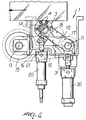
- the edge grinding unit 1 comprises a grinding wheel 2 which, in a per se known manner, is mounted inside a carousel element 3 which, as is known, is constituted by a cage formed by a plurality of rollers 4 being arranged circumferentially and being designed to engage the rim of the sheet and the edge being worked, so as to precisely determine the type of bevel to be made.
- the particularity of the invention consists in that for said grinding wheel 2 supporting means are provided which are constituted by a working arm 10 which supports said grinding wheel 2 at one end and at the other end thereof is articulated by means of a first pivot 11 to a coupling arm 12 which is in turn articulated, by means of a second pivot 13, to the fixed structure of the machine, generally designated by the reference numeral 14.
- the grinding wheel driving motor designated by the reference numeral 15, which drives a first belt 16 which winds around a pulley 17 which can rotate about the first pivot 11 and is coaxial to a pulley for driving a second belt 18 that turns the grinding wheel.
- the particularity of the invention therefore consists in that the grinding wheel 2 can oscillate about two separate pivots, i.e., a first oscillation pivot or axis 11 and a second oscillation pivot or axis 13.
- Actuation means are also provided, constituted by a first cylinder 20 which is articulated to the fixed structure 14 and whose actuation stem 21 is articulated to the working end of the working arm 10; there is also a second cylinder 30, whose stem 31 is articulated to the coupling arm 12 at the articulation end of the working arm 10.
- This arrangement makes it possible to produce the oscillation of the working arm 10 by means of the first cylinder 20 in a direction which in practice makes the grinding wheel work against the front edge of the plate, as shown in Figure 1 .
- the plate in practice causes the working arm to rotate in the opposite direction, so that the carousel element slides along the longitudinal rim of the plate until, when the rear edge reaches the grinding wheel, the second cylinder 30 is actuated and, by producing an oscillation of the coupling arm 12 in a direction which is the opposite of the working oscillation of the first arm 10, allows the grinding wheel to follow the rear edge in order to perform the required work.
- the grinding wheel can return into position immediately after working the rear edge, thus eliminating the idle times between one plate and the next that occur in the solutions of the known art, in which the grinding wheel was subjected to an oscillation in order to make contact with the edge and to a translational motion in order to follow the rear edge to work it.
- the two oscillations which can be performed with actuators constituted by cylinders allows first of all to reduce return times significantly; moreover, by connecting the grinding wheel driving motor at the second pivot 13, which is in a fixed position, the moving masses are smaller, thus reducing the impacts between the grinding wheel and the plate and accordingly reducing the possibility of breakage.
- an edge grinding unit is provided which, by using two separate oscillations about different pivots and with opposite rotations, allows to increase significantly the operating speeds, since the grinding wheel, after completing the working of the rear edge, returns very rapidly to the initial position for working the front edge of the next plate.
- the materials used, as well as the contingent shapes and dimensions may be any according to requirements.
Landscapes
- Engineering & Computer Science (AREA)
- Mechanical Engineering (AREA)
- Chemical & Material Sciences (AREA)
- Ceramic Engineering (AREA)
- Inorganic Chemistry (AREA)
- Grinding And Polishing Of Tertiary Curved Surfaces And Surfaces With Complex Shapes (AREA)
- Re-Forming, After-Treatment, Cutting And Transporting Of Glass Products (AREA)
- Joining Of Glass To Other Materials (AREA)
- Grinding Of Cylindrical And Plane Surfaces (AREA)
- Manufacture, Treatment Of Glass Fibers (AREA)
- Surface Treatment Of Glass (AREA)
- Basic Packing Technique (AREA)
Abstract
Description
- The present invention relates to an edge grinding unit for machines for working the edges of plates in general and of glass sheets in particular, as per the preamble of
claim 1. - An example of such a unit is disclosed by
FR 2 429 647 A - It is known that edge grinding units are currently applied to machines for working the edges of plates in general and of glass sheets in particular; in practice, such units are designed to produce a slight bevel at the edge of the plate.
- This operation, which is absolutely necessary in the case of glass sheets which must subsequently be subjected to tempering, is designed to bevel the edge and is performed by means of a grinding wheel which can rotate inside a carousel element constituted by a cage formed by a plurality of rollers which rest against the edge of the plate, so that the grinding wheel forms the bevel in the intended manner.
- In the solutions of the prior art, the edge grinding unit is generally constituted by an oscillating arm which supports a grinding wheel and is pushed by way of elastic means against the front edge of the incoming plate in order to bevel the front edge.
- Then, as it continues its translational motion, the plate in practice moves the arm so that the rollers engage the longitudinal edge, without contact between the grinding wheel and the plate, until once the grinding wheel has reached the rear edge, such grinding wheel rises to work the rear edge. The movement of the plate, albeit very slow, in many cases does not allow to work the rear edge correctly, since the movement of the arm and therefore of the grinding wheel occurs in the opposite direction with respect to the advancement of the glass sheet.
- In order to try to obviate this drawback, the edge grinding unit has been fitted on two linear guides so that when it makes contact with the glass sheet in order to work the front edge, the grinding wheel moves outwards and then follows said sheet, by means of the second slider, in order to work the rear edge thereof.
- In the solution of the known art there are considerable masses in motion, since the unit also supports the motor that actuates the grinding wheel; moreover, such unit must follow the plate for a certain extent and perform the return stroke.
- Accordingly, such edge grinding units force a reduction in the speed of translational motion of the plate, because the grinding wheel must follow, for a certain extent, the plate during the working of the rear edge thereof.
- Moreover, it is necessary to keep a certain distance between the contiguous plates, because after a rear edge has been worked, the arm with the corresponding grinding wheel must be returned to the initial condition by means of the translational return motion of the entire movable unit, so that the grinding wheel returns to the initial conditions in order to engage the front edge of the next plate.
- In this context, low operating speeds and considerable moving masses are involved and therefore collisions can occur between the grinding wheel and the plate being worked, with the consequent possibility of damaging said plate.
-
FR-A-2 429 647 - The aim of the invention is to eliminate the above mentioned drawbacks by providing an edge grinding unit for machines for working the edges of plates in general and of glass sheets in particular which allows to considerably increase operating speeds thereby increasing the speed of the translational motion of the plates being worked.
- Within this aim, an object of the invention is to provide an edge grinding unit which allows to reduce the distance between two contiguous plates being worked, thus reducing idle times.
- Another object of the present invention is to provide an edge grinding unit which allows to reduce the moving masses, thus allowing to apply lower pressures and reducing the impact that inevitably occurs when the plate contacts the grinding wheel; accordingly, the speed with which the glass sheet makes contact with the grinding wheel can be much higher, with the advantage of higher productivity of the machine.
- Another object of the present invention is to provide an edge grinding unit which thanks to its particular constructive characteristics, is capable of giving the greatest assurances of reliability and safety in use.
- In accordance with the invention, there is provided an edge grinding unit for machines for working the edges of plates in general and of glass sheets in particular, as defined in the appended
claim 1. - Further characteristics and advantages will become better apparent from the description of a preferred but not exclusive embodiment of an edge grinding unit for machines for working the edges of plates in general and of glass sheets in particular, illustrated only by way of non-limitative example in the accompanying drawings, wherein:
-
Figure 1 is a view of the edge grinding unit when the grinding wheel engages the front edge; -
Figure 2 is a view of the edge grinding unit during the step for engaging the carousel element with the longitudinal edge of the plate; and -
Figure 3 is a view of the step in which the grinding wheel engages the rear edge of the plate. - With reference to the figures, the edge grinding unit for machines for working the edges of plates in general and of glass sheets in particular, generally designated by the
reference numeral 1, is generally connected to the end of machines for working the edges of plates and, in the case of machines that work two opposite edges simultaneously, two edge grinding units are usually provided, one for each side, whereas in the case of machines that work only one edge of a plate, which is arranged for example vertically, there is a single edge grinding unit arranged vertically at the end of the working of said edge. - The
edge grinding unit 1 comprises agrinding wheel 2 which, in a per se known manner, is mounted inside acarousel element 3 which, as is known, is constituted by a cage formed by a plurality ofrollers 4 being arranged circumferentially and being designed to engage the rim of the sheet and the edge being worked, so as to precisely determine the type of bevel to be made. - The particularity of the invention consists in that for said grinding
wheel 2 supporting means are provided which are constituted by a workingarm 10 which supports said grindingwheel 2 at one end and at the other end thereof is articulated by means of afirst pivot 11 to acoupling arm 12 which is in turn articulated, by means of asecond pivot 13, to the fixed structure of the machine, generally designated by thereference numeral 14. - At said
second pivot 13 there is the grinding wheel driving motor, designated by thereference numeral 15, which drives afirst belt 16 which winds around apulley 17 which can rotate about thefirst pivot 11 and is coaxial to a pulley for driving asecond belt 18 that turns the grinding wheel. - The particularity of the invention therefore consists in that the
grinding wheel 2 can oscillate about two separate pivots, i.e., a first oscillation pivot oraxis 11 and a second oscillation pivot oraxis 13. - Actuation means are also provided, constituted by a
first cylinder 20 which is articulated to thefixed structure 14 and whoseactuation stem 21 is articulated to the working end of the workingarm 10; there is also asecond cylinder 30, whosestem 31 is articulated to thecoupling arm 12 at the articulation end of the workingarm 10. - This arrangement makes it possible to produce the oscillation of the working
arm 10 by means of thefirst cylinder 20 in a direction which in practice makes the grinding wheel work against the front edge of the plate, as shown inFigure 1 . - Once the front edge has been worked, the plate in practice causes the working arm to rotate in the opposite direction, so that the carousel element slides along the longitudinal rim of the plate until, when the rear edge reaches the grinding wheel, the
second cylinder 30 is actuated and, by producing an oscillation of thecoupling arm 12 in a direction which is the opposite of the working oscillation of thefirst arm 10, allows the grinding wheel to follow the rear edge in order to perform the required work. - With the described arrangement, in which the working movement of the grinding wheel is performed by way of two oscillations in the opposite directions about two distinct pivots, the grinding wheel can return into position immediately after working the rear edge, thus eliminating the idle times between one plate and the next that occur in the solutions of the known art, in which the grinding wheel was subjected to an oscillation in order to make contact with the edge and to a translational motion in order to follow the rear edge to work it.
- The two oscillations which can be performed with actuators constituted by cylinders allows first of all to reduce return times significantly; moreover, by connecting the grinding wheel driving motor at the
second pivot 13, which is in a fixed position, the moving masses are smaller, thus reducing the impacts between the grinding wheel and the plate and accordingly reducing the possibility of breakage. - From the above description it is evident that the invention achieves the intended aim and objects, and in particular the fact is stressed that an edge grinding unit is provided which, by using two separate oscillations about different pivots and with opposite rotations, allows to increase significantly the operating speeds, since the grinding wheel, after completing the working of the rear edge, returns very rapidly to the initial position for working the front edge of the next plate.
- The invention thus conceived is susceptible of numerous modifications and variations, all of which are within the scope of the appended claims.
- In practice, the materials used, as well as the contingent shapes and dimensions, may be any according to requirements.
- Where technical features mentioned in any claim are followed by reference signs, those reference signs have been included for the sole purpose of increasing the intelligibility of the claims and accordingly, such reference signs do not have any limiting effect on the interpretation of each element identified by way of example by such reference signs.
Claims (3)
- An edge grinding unit for machines for working the edges of plates in general and of glass sheets in particular, comprising, at least one grinding wheel (2) arrangeable at a rim of a plate being worked, means (10) for supporting said grinding wheel (2) which form, for said grinding wheel (2), a first oscillation axis (11) and a second oscillation axis (13) which are spaced from each other and are substantially perpendicular to the advancement plane of said plate, said supporting means comprising a working arm (10) which supports said grinding wheel (2) at one end and is connected to a coupling arm (12) at the other end by way of a first pivot (11) forming said first oscillation axis, said coupling arm (12) being connected to the fixed structure (14) of the machine for working the edges of the plate by way of a second pivot (13) forming said second oscillation axis, characterized in that said grinding wheel being accommodated in a carousel element (3) provided with a rotatable cage formed by a plurality of circumferentially distributed rollers (4), and in that it comprises, at said second pivot (13), a motor (15) for driving said grinding wheel (2) which is connected to said grinding wheel (2) by way of a first belt (16) and a second belt (18) which respectively wind around pulleys (17) rotatable about said first pivot (11) that couples said coupling arm (12) and said working arm (10).
- The edge grinding unit according to claim 1, characterized in that it comprises means for actuating said arms (10,12) being constituted respectively by a first cylinder (20), which is articulated to said fixed structure (14) and is connected to said working arm (10), and by a second cylinder (30), which is articulated to said fixed structure (14) and is connected to said coupling arm (12).
- The edge grinding unit according to one or more of the preceding claims, characterized in that said working arm (10) is adapted to move said grinding wheel (2) so as to work against a front edge of the plate by rotation in one direction and said coupling arm (12) is adapted to place said grinding wheel at the rear edge of the plate by rotation in an opposite direction.
Applications Claiming Priority (2)
| Application Number | Priority Date | Filing Date | Title |
|---|---|---|---|
| IT2000MI002049A IT1318885B1 (en) | 2000-09-20 | 2000-09-20 | EDGING UNIT FOR MACHINES FOR THE PROCESSING OF THE EDGES OF SLABS IN GENERAL AND IN PARTICULAR OF GLASS SLABS. |
| ITMI002049 | 2000-09-20 |
Publications (2)
| Publication Number | Publication Date |
|---|---|
| EP1190816A1 EP1190816A1 (en) | 2002-03-27 |
| EP1190816B1 true EP1190816B1 (en) | 2008-03-12 |
Family
ID=11445830
Family Applications (1)
| Application Number | Title | Priority Date | Filing Date |
|---|---|---|---|
| EP01120716A Expired - Lifetime EP1190816B1 (en) | 2000-09-20 | 2001-09-04 | Apparatus for working the edges of glass plates |
Country Status (10)
| Country | Link |
|---|---|
| US (1) | US6602120B2 (en) |
| EP (1) | EP1190816B1 (en) |
| JP (1) | JP2002154039A (en) |
| KR (1) | KR100800034B1 (en) |
| CN (1) | CN1191149C (en) |
| AT (1) | ATE388789T1 (en) |
| DE (1) | DE60133165T2 (en) |
| ES (1) | ES2301508T3 (en) |
| IT (1) | IT1318885B1 (en) |
| TW (1) | TW503159B (en) |
Cited By (1)
| Publication number | Priority date | Publication date | Assignee | Title |
|---|---|---|---|---|
| EP2974826A2 (en) | 2014-07-17 | 2016-01-20 | Schott AG | Method for the highly precise corner contouring of flat glass substrates in continuous flow |
Families Citing this family (17)
| Publication number | Priority date | Publication date | Assignee | Title |
|---|---|---|---|---|
| US7815493B2 (en) * | 2002-10-11 | 2010-10-19 | Cinetic Landis Corp. | Apparatus and method for positioning a device near a workpiece during machining operations |
| US7018272B2 (en) * | 2003-07-29 | 2006-03-28 | Corning Incorporated | Pressure feed grinding of AMLCD substrate edges |
| US7294045B1 (en) | 2005-12-21 | 2007-11-13 | Corning Incorporated | Apparatus and method for edge processing of a glass sheet |
| US7235002B1 (en) * | 2006-01-23 | 2007-06-26 | Guardian Industries Corp. | Method and system for making glass sheets including grinding lateral edge(s) thereof |
| JP2008284684A (en) * | 2007-05-21 | 2008-11-27 | Applied Materials Inc | Method and apparatus for polishing an edge of a substrate using a polishing arm |
| DE102008027050A1 (en) * | 2008-06-06 | 2009-12-10 | Grenzebach Maschinenbau Gmbh | Method and device for automatic edge grinding of glass plates under clean room conditions |
| TWI490061B (en) * | 2009-03-19 | 2015-07-01 | Siemag Gmbh | Verfahren und vorrichtung zum schleifen eines stranggussprodukts |
| IT1393877B1 (en) * | 2009-04-29 | 2012-05-11 | Bottero Spa | ROMPISPIGOLO GROUP FOR THE SMUSSO OF SPIDES OF GLASS SLABS |
| EP2501519A1 (en) * | 2009-11-17 | 2012-09-26 | Mbd S.R.L. | Method for smoothing-polishing surfaces of stone materials and machine associated with said method |
| US20110151753A1 (en) * | 2009-12-22 | 2011-06-23 | Charles Gottschalk | Edge grinding apparatus |
| JP5031087B2 (en) * | 2010-12-29 | 2012-09-19 | AvanStrate株式会社 | Manufacturing method of glass substrate |
| CN102161174A (en) * | 2011-01-31 | 2011-08-24 | 张家港市恒久玻璃机械有限公司 | Glass chamfering machine |
| CN102806500A (en) * | 2012-09-04 | 2012-12-05 | 张家港市广丰玻璃有限公司 | Chamfering machine |
| CN105549545B (en) * | 2016-02-19 | 2018-06-08 | 泉州华中科技大学智能制造研究院 | A kind of control algolithm based on the grinding of edge polisher constant linear velocity |
| DE102017004237B4 (en) * | 2017-05-02 | 2018-11-15 | KAPP Werkzeugmaschinen GmbH | grinding machine |
| CN108115501B (en) * | 2017-11-20 | 2023-10-10 | 常州索高机械有限公司 | Biax feeding grinding wheel can beat formula glass chamfering mechanism |
| CN116276462B (en) * | 2022-12-13 | 2025-09-02 | 江山市康辉玻璃有限公司 | An edge grinding machine for glass production and its use method |
Family Cites Families (18)
| Publication number | Priority date | Publication date | Assignee | Title |
|---|---|---|---|---|
| US386A (en) * | 1837-09-21 | Improvement in machines for breaking and cleaning flax and hemp | ||
| US1997386A (en) * | 1931-10-30 | 1935-04-09 | Libbey Owens Ford Glass Co | Edge grinding apparatus |
| US2021198A (en) * | 1935-02-23 | 1935-11-19 | Pittsburgh Plate Glass Co | Machine for edging glass sheets |
| US2583758A (en) * | 1946-01-30 | 1952-01-29 | Clifford B Webber | Sickle grinder |
| US2561929A (en) * | 1948-05-27 | 1951-07-24 | G W Klages & Son Inc | Glass edging machine |
| IT1023816B (en) * | 1973-12-26 | 1978-05-30 | Intercontinental Trading Co | DEVICE FOR WORKING THE CORNERS OF A SHEET FOR CRYSTALS AND MIRRORS |
| JPS5442114B2 (en) * | 1974-05-30 | 1979-12-12 | ||
| DE2827917C2 (en) * | 1978-06-26 | 1982-12-30 | Bielefelder Union Bruno Koch, 4800 Bielefeld | Grinding machine for rounding the corners of rectangular, plate-shaped workpieces |
| DE2847192C2 (en) * | 1978-10-30 | 1980-10-02 | Goetze Ag, 5093 Burscheid | Machine for deburring or chamfering the edges of ring-shaped workpieces, especially piston rings |
| DK14583A (en) * | 1982-01-20 | 1983-07-21 | Saint Gobain Vitrage | PROCEDURE AND APPARATUS FOR POSITION CONTROL OF THE TOOL ON A GLASS WAVE MACHINE |
| JPS60167654A (en) * | 1984-02-09 | 1985-08-31 | Fuji Electric Co Ltd | Layer shortcircuit detector for field winding |
| JPS6165762A (en) * | 1984-09-06 | 1986-04-04 | Nippon Sheet Glass Co Ltd | Grinding device for end face of a plate |
| JPS6179559A (en) * | 1984-09-28 | 1986-04-23 | Nippon Sheet Glass Co Ltd | Edge polishing device |
| JPH0645328B2 (en) * | 1985-01-18 | 1994-06-15 | 日産自動車株式会社 | Tono board mounting structure |
| US5289661A (en) * | 1992-12-23 | 1994-03-01 | Texas Instruments Incorporated | Notch beveling on semiconductor wafer edges |
| IT1262263B (en) * | 1993-12-30 | 1996-06-19 | Delle Vedove Levigatrici Spa | SANDING PROCEDURE FOR CURVED AND SHAPED PROFILES AND SANDING MACHINE THAT REALIZES SUCH PROCEDURE |
| US5479971A (en) * | 1994-08-01 | 1996-01-02 | Marshall; Lorry L. | Dual action tree cutting apparatus |
| US5980364A (en) * | 1998-07-21 | 1999-11-09 | Bentley; Richard | Method and apparatus for cutting rings from forging stock |
-
2000
- 2000-09-20 IT IT2000MI002049A patent/IT1318885B1/en active
-
2001
- 2001-09-04 AT AT01120716T patent/ATE388789T1/en not_active IP Right Cessation
- 2001-09-04 DE DE60133165T patent/DE60133165T2/en not_active Expired - Lifetime
- 2001-09-04 ES ES01120716T patent/ES2301508T3/en not_active Expired - Lifetime
- 2001-09-04 EP EP01120716A patent/EP1190816B1/en not_active Expired - Lifetime
- 2001-09-04 TW TW090121860A patent/TW503159B/en not_active IP Right Cessation
- 2001-09-06 US US09/946,336 patent/US6602120B2/en not_active Expired - Fee Related
- 2001-09-12 KR KR1020010056254A patent/KR100800034B1/en not_active Expired - Fee Related
- 2001-09-14 JP JP2001279619A patent/JP2002154039A/en active Pending
- 2001-09-20 CN CNB011408308A patent/CN1191149C/en not_active Expired - Fee Related
Cited By (3)
| Publication number | Priority date | Publication date | Assignee | Title |
|---|---|---|---|---|
| EP2974826A2 (en) | 2014-07-17 | 2016-01-20 | Schott AG | Method for the highly precise corner contouring of flat glass substrates in continuous flow |
| DE102014213953A1 (en) | 2014-07-17 | 2016-01-21 | Schott Ag | Process for high-precision corner contouring of flat glass substrates in a continuous process |
| US9751183B2 (en) | 2014-07-17 | 2017-09-05 | Schott Ag | Method for high-precision corner contouring of flat glass substrates in a continuous feed-through process |
Also Published As
| Publication number | Publication date |
|---|---|
| DE60133165D1 (en) | 2008-04-24 |
| EP1190816A1 (en) | 2002-03-27 |
| ITMI20002049A0 (en) | 2000-09-20 |
| ES2301508T3 (en) | 2008-07-01 |
| KR100800034B1 (en) | 2008-01-31 |
| IT1318885B1 (en) | 2003-09-10 |
| KR20020022574A (en) | 2002-03-27 |
| ATE388789T1 (en) | 2008-03-15 |
| CN1191149C (en) | 2005-03-02 |
| CN1344596A (en) | 2002-04-17 |
| JP2002154039A (en) | 2002-05-28 |
| TW503159B (en) | 2002-09-21 |
| ITMI20002049A1 (en) | 2002-03-20 |
| US20020034927A1 (en) | 2002-03-21 |
| DE60133165T2 (en) | 2009-03-19 |
| US6602120B2 (en) | 2003-08-05 |
Similar Documents
| Publication | Publication Date | Title |
|---|---|---|
| US6602120B2 (en) | Edge grinding unit for edge working machines | |
| US7353685B2 (en) | Apparatus for punching, stamping and/or shaping flat elements | |
| JP5224274B2 (en) | Method and apparatus for bending metal plate | |
| US4064659A (en) | Apparatus for centering sheets of glass on the platform of a machine | |
| CN119018532B (en) | Novel flammulina velutipes raw material warehouse-out machine | |
| CN111036748B (en) | Environment-friendly sand-proof dust suppression net processing machine | |
| CA1073340A (en) | Manufacture of a window by breaking the edges of a sheet of glass along a score | |
| EP1174214A1 (en) | Apparatus for working the edges of glass plates | |
| KR20130001637A (en) | Sizing device | |
| CN112496146B (en) | High-precision numerical control hydraulic punch press | |
| EP0669174B1 (en) | Machine for bending sheets of metal | |
| US5794481A (en) | Device for bending or curving hollow-section strips | |
| EP0123478B1 (en) | Workpiece-handling apparatus | |
| KR100441670B1 (en) | Thomson press | |
| US5709123A (en) | Press working machine with a vertically movable lower mold and a horizontally movable workpiece carrier | |
| US5110026A (en) | Apparatus for a stepwise advancing of a web-shaped workpiece | |
| KR20200095855A (en) | Automatic cutting device | |
| CN117086174B (en) | Multi-station stamping equipment for automobile part production | |
| US3990286A (en) | Piece working machine for the production of punches and/or matrices | |
| JP2558778Y2 (en) | Hemming machine | |
| SU1096017A1 (en) | Machine for bending mounting loops and anchors | |
| CN209792747U (en) | Shearing mechanism of plate shearing machine for producing supports | |
| KR200218812Y1 (en) | device for hitting and engraving a mark on strip surface | |
| KR100440000B1 (en) | A pipe bender | |
| JPS6261739A (en) | Press material feed motion curve changing device |
Legal Events
| Date | Code | Title | Description |
|---|---|---|---|
| PUAI | Public reference made under article 153(3) epc to a published international application that has entered the european phase |
Free format text: ORIGINAL CODE: 0009012 |
|
| AK | Designated contracting states |
Kind code of ref document: A1 Designated state(s): AT BE CH CY DE DK ES FI FR GB GR IE IT LI LU MC NL PT SE TR |
|
| AX | Request for extension of the european patent |
Free format text: AL;LT;LV;MK;RO;SI |
|
| 17P | Request for examination filed |
Effective date: 20020801 |
|
| AKX | Designation fees paid |
Free format text: AT BE CH CY DE DK ES FI FR GB GR IE IT LI LU MC NL PT SE TR |
|
| RAP1 | Party data changed (applicant data changed or rights of an application transferred) |
Owner name: KYRO ITALY S.P.A. |
|
| RAP1 | Party data changed (applicant data changed or rights of an application transferred) |
Owner name: Z. BAVELLONI S.P.A. |
|
| 17Q | First examination report despatched |
Effective date: 20070112 |
|
| GRAP | Despatch of communication of intention to grant a patent |
Free format text: ORIGINAL CODE: EPIDOSNIGR1 |
|
| RAP1 | Party data changed (applicant data changed or rights of an application transferred) |
Owner name: GLASTON ITALY SPA |
|
| GRAS | Grant fee paid |
Free format text: ORIGINAL CODE: EPIDOSNIGR3 |
|
| GRAA | (expected) grant |
Free format text: ORIGINAL CODE: 0009210 |
|
| AK | Designated contracting states |
Kind code of ref document: B1 Designated state(s): AT BE CH CY DE DK ES FI FR GB GR IE IT LI LU MC NL PT SE TR |
|
| REG | Reference to a national code |
Ref country code: GB Ref legal event code: FG4D |
|
| REG | Reference to a national code |
Ref country code: CH Ref legal event code: EP |
|
| REG | Reference to a national code |
Ref country code: IE Ref legal event code: FG4D |
|
| REF | Corresponds to: |
Ref document number: 60133165 Country of ref document: DE Date of ref document: 20080424 Kind code of ref document: P |
|
| REG | Reference to a national code |
Ref country code: ES Ref legal event code: FG2A Ref document number: 2301508 Country of ref document: ES Kind code of ref document: T3 |
|
| PG25 | Lapsed in a contracting state [announced via postgrant information from national office to epo] |
Ref country code: FI Free format text: LAPSE BECAUSE OF FAILURE TO SUBMIT A TRANSLATION OF THE DESCRIPTION OR TO PAY THE FEE WITHIN THE PRESCRIBED TIME-LIMIT Effective date: 20080312 |
|
| PG25 | Lapsed in a contracting state [announced via postgrant information from national office to epo] |
Ref country code: AT Free format text: LAPSE BECAUSE OF FAILURE TO SUBMIT A TRANSLATION OF THE DESCRIPTION OR TO PAY THE FEE WITHIN THE PRESCRIBED TIME-LIMIT Effective date: 20080312 |
|
| NLV1 | Nl: lapsed or annulled due to failure to fulfill the requirements of art. 29p and 29m of the patents act | ||
| PG25 | Lapsed in a contracting state [announced via postgrant information from national office to epo] |
Ref country code: BE Free format text: LAPSE BECAUSE OF FAILURE TO SUBMIT A TRANSLATION OF THE DESCRIPTION OR TO PAY THE FEE WITHIN THE PRESCRIBED TIME-LIMIT Effective date: 20080312 |
|
| PG25 | Lapsed in a contracting state [announced via postgrant information from national office to epo] |
Ref country code: PT Free format text: LAPSE BECAUSE OF FAILURE TO SUBMIT A TRANSLATION OF THE DESCRIPTION OR TO PAY THE FEE WITHIN THE PRESCRIBED TIME-LIMIT Effective date: 20080818 Ref country code: SE Free format text: LAPSE BECAUSE OF FAILURE TO SUBMIT A TRANSLATION OF THE DESCRIPTION OR TO PAY THE FEE WITHIN THE PRESCRIBED TIME-LIMIT Effective date: 20080612 |
|
| PG25 | Lapsed in a contracting state [announced via postgrant information from national office to epo] |
Ref country code: NL Free format text: LAPSE BECAUSE OF FAILURE TO SUBMIT A TRANSLATION OF THE DESCRIPTION OR TO PAY THE FEE WITHIN THE PRESCRIBED TIME-LIMIT Effective date: 20080312 |
|
| ET | Fr: translation filed | ||
| PLBE | No opposition filed within time limit |
Free format text: ORIGINAL CODE: 0009261 |
|
| STAA | Information on the status of an ep patent application or granted ep patent |
Free format text: STATUS: NO OPPOSITION FILED WITHIN TIME LIMIT |
|
| PG25 | Lapsed in a contracting state [announced via postgrant information from national office to epo] |
Ref country code: DK Free format text: LAPSE BECAUSE OF FAILURE TO SUBMIT A TRANSLATION OF THE DESCRIPTION OR TO PAY THE FEE WITHIN THE PRESCRIBED TIME-LIMIT Effective date: 20080312 |
|
| 26N | No opposition filed |
Effective date: 20081215 |
|
| PG25 | Lapsed in a contracting state [announced via postgrant information from national office to epo] |
Ref country code: MC Free format text: LAPSE BECAUSE OF NON-PAYMENT OF DUE FEES Effective date: 20080930 |
|
| REG | Reference to a national code |
Ref country code: CH Ref legal event code: PL |
|
| PG25 | Lapsed in a contracting state [announced via postgrant information from national office to epo] |
Ref country code: IE Free format text: LAPSE BECAUSE OF NON-PAYMENT OF DUE FEES Effective date: 20080904 |
|
| PG25 | Lapsed in a contracting state [announced via postgrant information from national office to epo] |
Ref country code: CY Free format text: LAPSE BECAUSE OF FAILURE TO SUBMIT A TRANSLATION OF THE DESCRIPTION OR TO PAY THE FEE WITHIN THE PRESCRIBED TIME-LIMIT Effective date: 20080312 |
|
| PG25 | Lapsed in a contracting state [announced via postgrant information from national office to epo] |
Ref country code: CH Free format text: LAPSE BECAUSE OF NON-PAYMENT OF DUE FEES Effective date: 20080930 Ref country code: LI Free format text: LAPSE BECAUSE OF NON-PAYMENT OF DUE FEES Effective date: 20080930 |
|
| PG25 | Lapsed in a contracting state [announced via postgrant information from national office to epo] |
Ref country code: LU Free format text: LAPSE BECAUSE OF NON-PAYMENT OF DUE FEES Effective date: 20080904 |
|
| PG25 | Lapsed in a contracting state [announced via postgrant information from national office to epo] |
Ref country code: TR Free format text: LAPSE BECAUSE OF FAILURE TO SUBMIT A TRANSLATION OF THE DESCRIPTION OR TO PAY THE FEE WITHIN THE PRESCRIBED TIME-LIMIT Effective date: 20080312 |
|
| PG25 | Lapsed in a contracting state [announced via postgrant information from national office to epo] |
Ref country code: GR Free format text: LAPSE BECAUSE OF FAILURE TO SUBMIT A TRANSLATION OF THE DESCRIPTION OR TO PAY THE FEE WITHIN THE PRESCRIBED TIME-LIMIT Effective date: 20080613 |
|
| PGFP | Annual fee paid to national office [announced via postgrant information from national office to epo] |
Ref country code: ES Payment date: 20140808 Year of fee payment: 14 Ref country code: GB Payment date: 20140820 Year of fee payment: 14 |
|
| PGFP | Annual fee paid to national office [announced via postgrant information from national office to epo] |
Ref country code: FR Payment date: 20140930 Year of fee payment: 14 Ref country code: DE Payment date: 20141027 Year of fee payment: 14 |
|
| REG | Reference to a national code |
Ref country code: DE Ref legal event code: R119 Ref document number: 60133165 Country of ref document: DE |
|
| GBPC | Gb: european patent ceased through non-payment of renewal fee |
Effective date: 20150904 |
|
| REG | Reference to a national code |
Ref country code: FR Ref legal event code: ST Effective date: 20160531 |
|
| PG25 | Lapsed in a contracting state [announced via postgrant information from national office to epo] |
Ref country code: DE Free format text: LAPSE BECAUSE OF NON-PAYMENT OF DUE FEES Effective date: 20160401 Ref country code: GB Free format text: LAPSE BECAUSE OF NON-PAYMENT OF DUE FEES Effective date: 20150904 |
|
| PG25 | Lapsed in a contracting state [announced via postgrant information from national office to epo] |
Ref country code: FR Free format text: LAPSE BECAUSE OF NON-PAYMENT OF DUE FEES Effective date: 20150930 |
|
| REG | Reference to a national code |
Ref country code: ES Ref legal event code: FD2A Effective date: 20161026 |
|
| PG25 | Lapsed in a contracting state [announced via postgrant information from national office to epo] |
Ref country code: ES Free format text: LAPSE BECAUSE OF NON-PAYMENT OF DUE FEES Effective date: 20150905 |
|
| PGFP | Annual fee paid to national office [announced via postgrant information from national office to epo] |
Ref country code: IT Payment date: 20200904 Year of fee payment: 20 |