EP1189332A2 - Motor with integrated harmonic drive gearbox - Google Patents
Motor with integrated harmonic drive gearbox Download PDFInfo
- Publication number
- EP1189332A2 EP1189332A2 EP01120391A EP01120391A EP1189332A2 EP 1189332 A2 EP1189332 A2 EP 1189332A2 EP 01120391 A EP01120391 A EP 01120391A EP 01120391 A EP01120391 A EP 01120391A EP 1189332 A2 EP1189332 A2 EP 1189332A2
- Authority
- EP
- European Patent Office
- Prior art keywords
- motor according
- toothing
- segments
- yoke
- bell
- Prior art date
- Legal status (The legal status is an assumption and is not a legal conclusion. Google has not performed a legal analysis and makes no representation as to the accuracy of the status listed.)
- Withdrawn
Links
Images


Classifications
-
- H—ELECTRICITY
- H02—GENERATION; CONVERSION OR DISTRIBUTION OF ELECTRIC POWER
- H02K—DYNAMO-ELECTRIC MACHINES
- H02K41/00—Propulsion systems in which a rigid body is moved along a path due to dynamo-electric interaction between the body and a magnetic field travelling along the path
- H02K41/06—Rolling motors, i.e. motors having the rotor axis parallel to the stator axis and following a circular path as the rotor rolls around the inside or outside of the stator ; Nutating motors, i.e. having the rotor axis parallel to the stator axis inclined with respect to the stator axis and performing a nutational movement as the rotor rolls on the stator
Definitions
- the invention relates to a motor with an integrated Harmonicdrive gearbox in the preamble of claim 1 defined genus.
- Harmonicdrive gearboxes also called wave gearboxes
- Harmonicdrive gearboxes have that The advantage of a very high reduction with a compact design.
- Such a Harmonicdrive gear becomes elastic deformable element (Flexspline) with external teeth with an internal toothing that is a few teeth larger (Cirularspline) rolled off by oval deformation.
- Harmonic Piezodrive miniaturized servo drive VDI / Z special drive technology April 99, page 15, Oliver Barth: "Harmonic Piezodrive, a miniaturizable servo drive ”
- Harmonic Piezodrive miniaturized servo drive VDI / Z special drive technology April 99, page 15, Oliver Barth: "Harmonic Piezodrive, a miniaturizable servo drive ”
- Hardspline elastic deformable element
- the motor according to the invention with an integrated harmonic drive gear has the advantage of a compact, flat design with very high output torque and extreme dynamics. There in him only the magnetic field and no large mass at high speed circulates, it is highly dynamic and generates a high Torque at low speeds.
- the engine is simple composed of a few repeating parts and light to assemble. Because of its flat design and its high
- the output torque is as a servomotor, especially in Motor vehicles, suitable for any positioning tasks. So can he e.g. as a selector motor or shift motor in automatic gearboxes with its fast ramp-up the switching times shorten considerably. When used in window regulators or He can almost see sunroofs when a jam occurs be stopped without delay.
- the outer element has a plurality of on one Output shaft coaxial dividing circle arranged equidistant Electromagnets, each electromagnet a U-shaped Yoke with two radially extending yoke legs and a connecting, axially aligned yoke web having.
- An outer toothing section is arranged on the yoke legs.
- the yoke is preferably laminated, and each is made of wedge-shaped rolled sheet metal strip has yoke a one-piece molded tooth of the internal toothing. The thickness of the slats is due to the tooth pitch Internal teeth given.
- the external teeth are arranged in bell tongues is preferably formed on a flexible ring which the free ends of the bell tongues on the outer element enclosing facing outer surface. While the bell is off a material with good magnetic properties is made, the flexible ring is made of spring steel manufactured and is therefore more wear-resistant than magnetic better materials.
- the inner element with external teeth from a variety of radially aligned segments composed by at least one spring ring displaceable in the radial direction are held, each segment preferably one integrally molded tooth of the external teeth.
- the thickness of the segments is again due to the tooth pitch the external toothing.
- the segments in at least one non-rotatably connected to the output shaft cylindrical driver held the segments in Radial slots slidably accommodates.
- two drivers on the output shaft at an axial distance arranged from each other, and in the circumferential direction successive segments, each with two axially teeth that are spaced apart from one another are rotated by 180 ° each alternately used in one and the other driver.
- the yokes of the electromagnets carry the on both pole faces Yoke leg an internal gear section one of two arranged in an axial distance from each other, ring-shaped Internal gears.
- Integrated harmonic drive gear in the following harmonic magnetic motor called, has a fixed outer element 11 with an annular internal toothing 12 in FIGS. 1-3 and in Figures 4-6 two axially spaced apart Internal gears 12, 12 'and one of the outer element 11 concentrically enclosed inner element 13 with in FIGS. 1-3 an external toothing 14 and two of them in FIGS. 4-6 axially spaced external toothings 14, 14 ', whose on the full number of teeth by at least two teeth is smaller than the number of teeth of the internal toothing 12 or 12 '.
- the division of internal and external gearing is the same.
- the inner element 13 is non-rotatably seated on a coaxial Output shaft 15 and is in the region of its ring-shaped External teeth 14, 14 'flexible, so that the External teeth 14, 14 'is oval deformable and thus with successive gear sections in the Internal teeth 12, 12 'can engage, which is Inner element 13 overall by oval deformation on the Internal toothing 12, 12 'rolls.
- the oval deformation will thereby by means of at least one rotating around the outer element 11 Magnetic field causes that in the area of the teeth 12, 14th or 12 ', 14' one on an external toothing section 141 acting, radially outward magnetic force (arrow 16 in Fig. 1).
- the outer element 11 has a plurality of electromagnets 17, the on a 15 coaxial to the output shaft dividing circle are arranged equidistant.
- the number of electromagnets 17 is preferably greater than six, but should not be too large be chosen because with it the effort for the electronics increases. A large number of electromagnets 17 lead to a more even process of passing on the External teeth 14, 14 'of the inner element 13 on the Internal teeth 12, 12 'on the outer element 11.
- everyone Electromagnet 17 has a U-shaped yoke 18 with two Yoke legs 181, 182 and one the yoke legs 181, 182 connecting yoke web 183.
- the yokes are 18 arranged so that the yoke legs 181, 182 radially are aligned and the yoke web 183 is in the axial direction extends. There is a magnetic coil 19 on each yoke web 183 arranged.
- the internal toothing 12 or 12 'of the outer element 11 is in the exemplary embodiments on eight electromagnets 17 divided, each with an internal gear section 121, 121 'is assigned to an electromagnet 17 and on the from the free ends of the yoke legs 181, 182 formed pole faces facing the inner element 13 are arranged.
- the yokes 18 are laminated wedge-shaped rolled sheet metal strip, and each Yoke plate carries one tooth of the internal toothing 12 or two Teeth of the internal toothing 12 ', which is integrally formed or which are molded in one piece.
- the yoke blades are out wedge-shaped rolled sheet metal strip, and their thickness depends on the tooth pitch of the internal toothing 12.
- harmonic magnetic motor in 1-3 are only on the lower yoke leg 181 of the Electromagnet 17 arranged internal toothing sections 121, which together form a coaxial ring gear Add tooth-free sections in between.
- the Exemplary embodiment of the harmonic magnetic motor according to FIG. 4 - 6 carry both the yoke legs 181 and Yoke leg 182 on their pole faces Internal toothing sections 121 and 121 ', each in same way to a ring gear with intermediate complete toothless sections.
- the inner element 13 is in the embodiment of the 1 - 3 as bell 20 with harmonic magnetic motor Bell bottom 201 and bell jacket 202 formed, the Bell jacket 202 from the edge of the bell to the bottom of the bell 201 is slotted, so that a variety of in Circumferential direction of adjacent flexible Bell tongues 21 results (Fig. 2).
- Bell 20 is off made of ferromagnetic material.
- the free ends of the Bell tongues 21 are on the outer element 11 facing outer surface of a flexible ring 22nd enclosed, which carries the external toothing 14.
- the flexible one Ring 22 with external teeth 14 is made of spring steel manufactured.
- the mode of operation of the Hamonic magnetic motor according to FIGS. 1-3 is as follows:
- the tooth segments 23, 24 are made of ferromagnetic material, namely from profile rolled sheet metal strips, the thickness of which by the Tooth pitch of the external toothing 14 of the inner element 13 is determined.
- the tooth angle of the teeth 25, 25 determines that removable torque on the output shaft 15.
- the segments 23, 24 are in two drivers 28, 28 ' added, which are rotationally fixed on the Output shaft 15 sit.
- Each driver 28, 28 ' has one half of the number of segments 23, 24 corresponding number of Radial slots 29 that are slightly wider than the thickness of the Segments 23, 24 are executed.
- the segments 23 are in the radial slots 29 of the driver 28 and the segments 24 inserted into the radial slots 29 of the driver 28 '. there the segments 23, 24 remain in their respective radial slots 29 radially displaceable.
- the outer element 11 carries two at the same distance as the external teeth 14, 14 ' of the inner element 13 arranged internal teeth 12, 12 ', from which the internal toothing 12 in turn Internal gear sections 121 is composed, which the pole faces of the yoke legs 181 of the electromagnets 17 are formed, and the internal toothing 12 ' Internal gear sections 121 'is composed, which the pole faces of the yoke legs 182 are formed.
- the Internal teeth 12 and 12 ' have the same number of teeth, which in the same way as in Figs. 1-3, i.e. at least by two teeth, is greater than the number of teeth also identically designed external gears 14 and 14 '.
- each driver 28, 28 ' has a cylindrical part 281 or 281 'and a flange 282 and 282', the Radial slots 29 in the cylinder part 281 or 281 ' are introduced, while the flange 282 and 282 ' Segments 23, 24 overlaps in the radial direction, so that the Segments 23, 24 essentially in the axial direction immovable between the flange parts 282 and 282 'of Carriers 28, 28 'are held.
- the invention is not based on those described Embodiment limited. So with appropriate Concession to the size of the harmonic magnetic motor according to the embodiment of FIGS. 4-6 with only one Internal and external teeth are executed. In this In this case, all segments are in a single carrier recorded and wear only one on their outer edge Tooth of the external toothing. The outer element is then as in the embodiment of FIGS. 1-3 executed, ie with provided only with an internal toothing.
Landscapes
- Engineering & Computer Science (AREA)
- Physics & Mathematics (AREA)
- Chemical & Material Sciences (AREA)
- Combustion & Propulsion (AREA)
- Electromagnetism (AREA)
- Power Engineering (AREA)
- Connection Of Motors, Electrical Generators, Mechanical Devices, And The Like (AREA)
- Retarders (AREA)
- Dynamo-Electric Clutches, Dynamo-Electric Brakes (AREA)
Abstract
Description
Die Erfindung betrifft einen Motor mit integriertem Harmonicdrive-Getriebe der im Oberbegriff des Anspruchs 1 definierten Gattung.The invention relates to a motor with an integrated Harmonicdrive gearbox in the preamble of claim 1 defined genus.
Bei vielen Anwendungen von Elektromotoren werden Antriebe mit hohen Momenten und relativ niedrigen Drehzahlen benötigt. Beispielsweise wird der Antrieb eines Scheibenwischers in einem Kraftfahrzeug mit maximal 65 min-1 betrieben und gibt ein maximales Moment von ca. 35 Nm ab. Da man hohe Leistungsdichten nur aus Elektromotoren mit sehr viel höheren Drehzahlen erhält, werden Elektromotoren für Wischerantriebe mit einem Untersetzungsgetriebe ausgestattet. Elektromotoren mit Untersetzungsgetriebe haben den Nachteil, daß die Dynamik des Antriebs sinkt, da die Massenträgheit des Motorläufers mit dem Quadrat der Übersetzung auf den Ausgang des Antriebs wirkt. In many applications of electric motors, drives with high torques and relatively low speeds are required. For example, the drive of a windshield wiper in a motor vehicle is operated at a maximum of 65 min -1 and emits a maximum torque of approximately 35 Nm. Since high power densities can only be obtained from electric motors with much higher speeds, electric motors for wiper drives are equipped with a reduction gear. Electric motors with reduction gears have the disadvantage that the dynamics of the drive decrease because the inertia of the motor rotor acts on the output of the drive with the square of the translation.
Für miniaturisierte Antriebe, beispielsweise bei Kleinstrobotern, Pumpen oder optischen Systemen, ist es bereits bekannt, Motoren mit integriertem Harmonicdrive-Getriebe der eingangs genannten Art zu verwenden. Harmonicdrive-Getriebe, auch Wellgetriebe genannt, haben den Vorteil einer sehr hohen Untersetzung bei kompakter Bauweise. Bei einem solchen Harmonicdrive-Getriebe wird ein elastisch verformbares Element (Flexspline) mit einer Außenverzahnung in einer um wenige Zähne größere Innenverzahnung (Cirularspline) durch ovale Verformung abgewälzt. Bei jeder Umdrehung eines innen laufenden Verformungselements wird das verformbare Element (Flexspline) um den Betrag am Umfang weiter gedreht, der der Differenzzähnezahl mal Teilung am Umfang entspricht.For miniaturized drives, for example at Small robots, pumps or optical systems, it is Already known, motors with integrated Harmonicdrive gear to use the type mentioned. Harmonicdrive gearboxes, also called wave gearboxes, have that The advantage of a very high reduction with a compact design. Such a Harmonicdrive gear becomes elastic deformable element (Flexspline) with external teeth with an internal toothing that is a few teeth larger (Cirularspline) rolled off by oval deformation. With everyone This is the rotation of an internal deformation element deformable element (flexspline) by the amount on the circumference rotated further, the number of differential teeth times the pitch on Scope corresponds.
Bei einem bekannten, als Harmonic Piezodrive bezeichneten
miniaturisierten Servoantrieb (VDI/Z Spezialantriebstechnik
April 99, Seite 15, Oliver Barth: "Harmonic Piezodrive, ein
miniaturisierbarer Servoantrieb") wird das elastisch
verformbare Element (Flexspline) durch radial um die
Getriebeachse angeordnete Piezoaktoren, die phasenverschoben
angesteuert werden, oval verformt.In a known, known as Harmonic Piezodrive
miniaturized servo drive (VDI / Z special drive technology
April 99,
Der erfindungsgemäße Motor mit integriertem Harmonicdrive-Getriebe hat den Vorteil einer kompakten, flachen Bauweise mit sehr hohem Abtriebsmoment und extremer Dynamik. Da in ihm nur das Magnetfeld und keine große Masse mit hoher Drehzahl umläuft, ist er hochdynamisch und erzeugt ein hohes Drehmoment bei niedrigen Drehzahlen. Der Motor ist einfach aus wenigen sich wiederholenden Teilen aufgebaut und leicht zu montieren. Wegen seiner flachen Bauweise und seiner hohen Ausgangsmomente ist er als Stellmotor, insbesondere in Kraftfahrzeugen, für beliebige Stellaufgaben geeignet. So kann er z.B. als Wählmotor oder Schaltmotor in Automatik-Schaltgetrieben mit seinem schnelle Hochlauf die Schaltzeiten erheblich verkürzen. Bei Verwendung in Fensterhebern oder Schiebedächern kann er beim Erkennen eines Klemmfalls nahezu verzögerungsfrei stillgesetzt werden.The motor according to the invention with an integrated harmonic drive gear has the advantage of a compact, flat design with very high output torque and extreme dynamics. There in him only the magnetic field and no large mass at high speed circulates, it is highly dynamic and generates a high Torque at low speeds. The engine is simple composed of a few repeating parts and light to assemble. Because of its flat design and its high The output torque is as a servomotor, especially in Motor vehicles, suitable for any positioning tasks. So can he e.g. as a selector motor or shift motor in automatic gearboxes with its fast ramp-up the switching times shorten considerably. When used in window regulators or He can almost see sunroofs when a jam occurs be stopped without delay.
Durch die in den weiteren Ansprüchen aufgeführten Maßnahmen sind vorteilhafte Weiterbildungen und Verbesserungen des im Anspruch 1 angegebenen Motors möglich.By the measures listed in the other claims are advantageous further developments and improvements in Claim 1 specified motor possible.
Gemäß einer vorteilhaften Ausführungsform der Erfindung weist das Außenelement eine Mehrzahl von auf einem zur Abtriebswelle koaxialen Teilerkreis äquidistant angeordneten Elektromagneten auf, wobei jeder Elektromagnet ein U-förmiges Joch mit zwei radial sich erstreckenden Jochschenkeln und einem diese verbindenden, axial ausgerichteten Jochsteg aufweist. An mindestens einer der dem Innenelement zugekehrten Polflächen an den freien Stirnenden der Jochschenkeln ist ein Außenverzahnungsabschnitt angeordnet. Vorzugsweise ist dabei das Joch lamelliert, und jede aus keilförmig gewalztem Blechband hergestellte Jochlamelle weist einen einstückig angeformten Zahn der Innenverzahnung auf. Die Dicke der Lamellen ist durch die Zahnteilung der Innenverzahnung gegeben.According to an advantageous embodiment of the invention the outer element has a plurality of on one Output shaft coaxial dividing circle arranged equidistant Electromagnets, each electromagnet a U-shaped Yoke with two radially extending yoke legs and a connecting, axially aligned yoke web having. On at least one of the inner elements facing pole faces on the free ends of the An outer toothing section is arranged on the yoke legs. The yoke is preferably laminated, and each is made of wedge-shaped rolled sheet metal strip has yoke a one-piece molded tooth of the internal toothing. The thickness of the slats is due to the tooth pitch Internal teeth given.
Gemäß einer vorteilhaften Ausführungsform der Erfindung weist das Innenelement Glockenform auf, wobei der Glockenmantel so geschlitzt ist, daß der Glockenmantel aus einer Vielzahl von flexiblen Glockenzungen besteht. Am freien Ende der Glockenzungen ist die Außenverzahnung angeordnet, die vorzugsweise auf einem flexiblen Ring ausgebildet ist, der die freien Enden der Glockenzungen auf deren dem Außenelement zugekehrten Außenfläche umschließt. Während die Glocke aus einem Material mit guten magnetischen Eigenschaften hergestellt ist, ist der flexible Ring aus Federstahl gefertigt und ist somit verschleißbeständiger als magnetisch bessere Materialien.According to an advantageous embodiment of the invention the inner element bell shape, with the bell jacket so is slotted that the bell shell from a variety of flexible bell tongues. At the free end of the The external teeth are arranged in bell tongues is preferably formed on a flexible ring which the free ends of the bell tongues on the outer element enclosing facing outer surface. While the bell is off a material with good magnetic properties is made, the flexible ring is made of spring steel manufactured and is therefore more wear-resistant than magnetic better materials.
Gemäß einer alternativen Ausführungsform der Erfindung ist das Innenelement mit Außenverzahnung aus einer Vielzahl von radial ausgerichteten Segmenten zusammengesetzt, die durch mindestens einen Federring in Radialrichtung verschiebbar gehalten sind, wobei jedes Segment einen vorzugsweise einstückig angeformten Zahn der Außenverzahnung trägt. Die Dicke der Segmente ist dabei wiederum durch die Zahnteilung der Außenverzahnung festgelegt. In einer fertigungstechnisch günstigen konstruktiven Ausführungsform sind die Segmente in mindestens einem drehfest mit der Abtriebswelle verbundenen zylinderförmigen Mitnehmer gehalten, der die Segmente in Radialschlitzen längsverschieblich aufnimmt.According to an alternative embodiment of the invention the inner element with external teeth from a variety of radially aligned segments composed by at least one spring ring displaceable in the radial direction are held, each segment preferably one integrally molded tooth of the external teeth. The The thickness of the segments is again due to the tooth pitch the external toothing. In a manufacturing technology Favorable constructive embodiment are the segments in at least one non-rotatably connected to the output shaft cylindrical driver held the segments in Radial slots slidably accommodates.
Gemäß einer bevorzugten Ausführungsform der Erfindung sind auf der Abtriebswelle zwei Mitnehmer im Axialabstand voneinander angeordnet, und in Umfangsrichtung aufeinanderfolgende Segmente mit jeweils zwei axial voneinander beabstandeten Zähnen sind um jeweils 180° gedreht abwechselnd in den einen und anderen Mitnehmer eingesetzt. Die Joche der Elektromagnete tragen an beiden Polflächen der Jochschenkel einen Innenverzahnungsabschnitt einer von zwei im Axialabstand voneinander angeordneten, kranzförmigen Innenverzahnungen. Durch die Aufteilung der Segmente auf zwei gemeinsam auf der Abtriebswelle sitzenden Mitnehmer läßt sich eine wesentlich kleinere Zahnteilung und damit eine größere Zähnezahl der Innenverzahnung realisieren.According to a preferred embodiment of the invention two drivers on the output shaft at an axial distance arranged from each other, and in the circumferential direction successive segments, each with two axially teeth that are spaced apart from one another are rotated by 180 ° each alternately used in one and the other driver. The yokes of the electromagnets carry the on both pole faces Yoke leg an internal gear section one of two arranged in an axial distance from each other, ring-shaped Internal gears. By dividing the segments into two driver sitting together on the output shaft can be a much smaller tooth pitch and thus a larger one Realize the number of teeth of the internal toothing.
Die Erfindung ist anhand von der Zeichnung dargestellten Ausführungsbeispielen in der nachfolgenden Beschreibung näher erläutert. Es zeigen jeweils in schematischer Darstellung:
- Fig. 1
- einen Halbschnitt eines Harmonic-Magnetmotors gemäß Linie I - I in Fig. 2,
- Fig. 2
- eine Ansicht des Motors in Richtung II in Fig. 1,
- Fig. 3
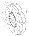
- eine perspektivische Darstellung der Ansicht des Motors gemäß Fig. 2 mit abgenommenem Außenverzahnungsring,
- Fig. 4
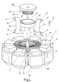
- eine perspektivische Ansicht eines Harmonic-Magnetmotors gemäß einem weiteren Ausführungsbeispiel mit einigen nach Art einer Explosionsdarstellung herausgezogenen Bauteilen,
- Fig. 5
- eine Draufsicht des Motors in Richtung Pfeil V in Fig. 4,
- Fig. 6
- einen Schnitt längs der Linie VI -VI in Fig. 5.
- Fig. 1
- 2 shows a half section of a harmonic magnetic motor according to line I - I in FIG. 2,
- Fig. 2
- a view of the engine in the direction II in Fig. 1,
- Fig. 3
- 2 shows a perspective view of the view of the motor according to FIG. 2 with the external toothing ring removed,
- Fig. 4
- 2 shows a perspective view of a harmonic magnetic motor according to a further exemplary embodiment with some components pulled out in the manner of an exploded illustration,
- Fig. 5
- a plan view of the engine in the direction of arrow V in Fig. 4,
- Fig. 6
- a section along the line VI-VI in Fig. 5th
Der in der Zeichnung in zwei verschiedenen
Ausführungsbeispielen dargestellte elektrische Motor mit
integriertem Harmonicdrive-Getriebe, im folgenden Harmonic-Magnetmotor
genannt, besitzt ein feststehendes Außenelement
11 mit in Fig. 1 - 3 einer ringförmigen Innenverzahnung 12
und in Fig. 4 - 6 zwei voneinander axial beabstandeten
Innenverzahnungen 12, 12' sowie ein von dem Außenelement 11
konzentrisch umschlossenes Innenelement 13 mit in Fig. 1 - 3
einer Außenverzahnung 14 und in Fig. 4 - 6 zwei voneinander
axial beabstandeten Außenverzahnungen 14, 14', deren auf den
vollen Umfang bezogene Zähnezahl um mindestens zwei Zähne
kleiner ist als die Zähnezahl der Innenverzahnung 12 bzw.
12'. Die Teilung von Innen- und Außenverzahnung ist gleich.
Das Innenelement 13 sitzt drehfest auf einer koaxialen
Abtriebswelle 15 und ist im Bereich seiner kranzförmigen
Außenverzahnung 14, 14' flexibel ausgebildet, so daß die
Außenverzahnung 14, 14' oval verformbar ist und dadurch mit
aufeinanderfolgenden Verzahnungsabschnitten in die
Innenverzahnung 12, 12' eingreifen kann, wobei sich das
Innenelement 13 insgesamt durch ovale Verformung auf der
Innenverzahnung 12, 12' abwälzt. Die ovale Verformung wird
dabei mittels mindestens eines am Außenelement 11 umlaufenden
Magnetfelds bewirkt, das im Bereich der Verzahnungen 12, 14
bzw. 12', 14' eine auf einen Außenverzahnungsabschnitt 141
wirkende, radial nach außen gerichtete Magnetkraft (Pfeil 16
in Fig. 1) erzeugt. In den dargestellten
Ausführungsbeispielen sind zwei diametral am Außenelement 11
angeordnete Magnetfelder vorhanden, die synchron umlaufen, so
daß jeweils einander diametral gegenüberliegende
Außenverzahnungsabschnitte 141 bzw. 141' in zwei mit geringem
Spaltabstand gegenüberliegende Innenverzahnungsabschnitte 121
bzw. 121' hineingezogen werden und dadurch das Innenelement
13 bei umlaufenden Magnetfeldern nach dem Reluktanzprinzip
gedreht wird. Aufgrund der sich nur gering unterscheidenden
Zähnezahl der geringfügig mehr Zähne aufweisenden
Innenverzahnung 12, 12' und der Außenverzahnung 14, 14' läuft
bei hoher Drehzahl des Magnetfelds die mit dem Innenelement
13 drehfest verbundene Abtriebswelle 15 mit nur geringer
Drehzahl um, so daß eine sehr große Untersetzung realisiert
werden kann. Das dabei vom Motor erzeugte Drehmoment hängt
wesentlich vom Winkel der gewählten Verzahnungen 12, 14 bzw.
12', 14' ab.The one in the drawing in two different
Electric motor shown with embodiments
Integrated harmonic drive gear, in the following harmonic magnetic motor
called, has a fixed
Bei beiden Ausführungsformen des Harmonic-Magnetmotors weist
das Außenelement 11 eine Mehrzahl von Elektromagneten 17 auf,
die auf einem zur Abtriebswelle 15 koaxialen Teilerkreis
äquidistant angeordnet sind. Die Zahl der Elektromagnete 17
ist vorzugsweise größer als sechs, soll aber nicht zu groß
gewählt werden, da mit ihr der Aufwand für die Elektronik
steigt. Eine große Anzahl von Elektromagneten 17 führt zu
einem gleichmäßigeren Verlauf der Abwälzung der
Außenverzahnung 14, 14' des Innenelements 13 auf der
Innenverzahnung 12, 12' am Außenelement 11. Jeder
Elektromagnet 17 weist ein U-förmiges Joch 18 mit zwei
Jochschenkeln 181, 182 und einem die Jochschenkel 181, 182
miteinander verbindenden Jochsteg 183 auf. Die Joche 18 sind
so angeordnet, daß die Jochschenkel 181, 182 radial
ausgerichtet sind und der Jochsteg 183 sich in Axialrichtung
erstreckt. Auf jedem Jochsteg 183, ist eine Magnetspule 19
angeordnet. Die Innenverzahnung 12 bzw. 12' des Außenelements
11 ist in den Ausführungsbeispielen auf acht Elektromagnete
17 aufgeteilt, wobei jeweils ein Innenverzahnungsabschnitt
121, 121' einem Elektromagneten 17 zugeordnet ist und auf den
von den freien Stirnseiten der Jochschenkel 181, 182
gebildeten Polflächen, die dem Innenelement 13 zugekehrt
sind, angeordnet sind. Die Joche 18 sind lamelliert aus
keilförmig gewalztem Blechband hergestellt, und jede
Jochlamelle trägt einen Zahn der Innenverzahnung 12 bzw. zwei
Zähne der Innenverzahnung 12', der einstückig angeformt ist
bzw. die einstückig angeformt sind. Die Jochlamellen sind aus
keilförmig gewalztem Blechband hergestellt, und ihre Dicke
richtet sich nach der Zahnteilung der Innenverzahnung 12.In both embodiments of the harmonic magnetic motor points
the
Im Ausführungsbeispiel des Harmonic-Magnetmotors in
Fig. 1 - 3 sind jeweils nur am unteren Jochschenkel 181 der
Elektromagnete 17 Innenverzahnungsabschnitte 121 angeordnet,
die sich in ihrer Gesamtheit zu einem koaxialen Zahnkranz mit
dazwischenliegenden zahnfreien Abschnitten ergänzen. Im
Ausführungsbeispiel des Harmonic-Magnetmotors gemäß Fig. 4 -
6 tragen sowohl die Jochschenkel 181 als auch die
Jochschenkel 182 auf ihren Polflächen
Innenverzahnungsabschnitte 121 bzw. 121', die sich jeweils in
gleicher Weise zu einem Zahnkranz mit dazwischenliegenden
zahnlosen Abschnitten ergänzen.In the exemplary embodiment of the harmonic magnetic motor in
1-3 are only on the
Das Innenelement 13 ist in dem Ausführungsbeispiel des
Harmonic-Magnetmotors gemäß Fig. 1 - 3 als Glocke 20 mit
Glockenboden 201 und Glockenmantel 202 ausgebildet, wobei der
Glockenmantel 202 vom Glockenrand aus bis zum Glockenboden
201 geschlitzt ist, so daß sich eine Vielzahl von in
Umfangsrichtung nebeneinanderliegenden flexiblen
Glockenzungen 21 ergibt (Fig. 2). Die Glocke 20 ist aus
ferromagnetischem Material hergestellt. Die freien Enden der
Glockenzungen 21 werden auf ihrer dem Außenelement 11
zugekehrten Außenfläche von einem flexiblen Ring 22
umschlossen, der die Außenverzahnung 14 trägt. Der flexible
Ring 22 mit Außenverzahnung 14 ist aus Federstahl
hergestellt.The
Die Wirkungsweise des Hamonic-Magnetmotors gemäß Fig. 1 - 3 ist wie folgt:The mode of operation of the Hamonic magnetic motor according to FIGS. 1-3 is as follows:
Werden die beiden diametral gegenüberliegenden Elektromagnete
17 erregt, wie dies durch die in die Magnetspule 19 in Fig. 1
eingezeichneten Stromrichtungen angedeutet ist, so wird
infolge des Magnetflusses im Joch 18, der sich über die
Glockenzungen 21 schließt, eine Magnetkraft (Pfeil 16 in
Fig. 1) zwischen dem freien Ende der Glockenzungen 21 und der
Polfläche des unteren Jochschenkels 181 erzeugt, so daß die
im Bereich des unteren Jochschenkels 181 liegenden
Glockenzungen 21 nach außen schwenken und dabei den flexiblen
Ring 22 oval verformen. Die Verformung des Rings 22 ist in
Fig. 2 dargestellt. Dabei werden die
Außenverzahnungsabschnitt 141 des flexiblen Rings 22 in die
Innenverzahnungsabschnitte 121 am Jochschenkel 181
hineingedrückt. Wegen der unterschiedlichen Zähnezahl der
Verzahnungsabschnitte 141, 121 dreht sich das Innenelement 13
um einen Bruchteil der Zahnteilung der Außenverzahnung 141
weiter. Nunmehr werden die beiden in Drehrichtung des
Innenelements 13 folgenden, diametral gegenüberliegenden
Elektromagnete 17 bestromt, wodurch sich der gleiche Vorgang
abspielt, so daß sich insgesamt mit aufeinanderfolgender
Bestromung der Elektromagnete 17, die von den diametralen
Elektromagneten 17 jeweils erzeugten Magnetfelder sich drehen
und dadurch das Innenelement 13 in eine Drehung versetzt
wird, die gegenüber der Drehung des Magnetfelds sehr stark
untersetzt ist.Will the two diametrically
In dem Ausführungsbeispiel des Harmonic-Magnetmotors gemäß
Fig. 4 - 6 ist das Innenelement 13 aus einer Vielzahl von
radial ausgerichteten Segmenten 23, 24 zusammengesetzt, die
ringartig hintereinander gereiht sind, wobei sich in
Umfangsrichtung immer ein Segment 23 mit einem Segment 24
abwechselt. Beide Segmente 23, 24 sind identisch ausgebildet
und um 180° gegeneinander verdreht angeordnet. Jedes Segment
trägt an seiner Außenseite zwei axial beabstandete Zähne 25
bzw. 25' und nahe seiner Innenkante zwei Axialschlitze 26,
26', die in Achsrichtung miteinander fluchten und von
voneinander abgekehrten Stirnseiten der Segmente 23, 24 her
eingebracht sind. Die Axialschlitze 26, 26' dienen zum
Einlegen von zwei Federringen 27, 27'. Die Zahnsegmente 23,
24 sind aus ferromagnetischem Material hergestellt, und zwar
aus profilgewalzten Blechstreifen, deren Dicke durch die
Zahnteilung der Außenverzahnung 14 des Innenelements 13
bestimmt ist. Der Zahnwinkel der Zähne 25, 25' bestimmt das
an der Abtriebswelle 15 abnehmbare Drehmoment.In the exemplary embodiment of the harmonic magnetic motor according to
4-6 is the
Die Segmente 23, 24 sind in zwei Mitnehmern 28, 28'
aufgenommen, die im Axialabstand voneinander drehfest auf der
Abtriebswelle 15 sitzen. Jeder Mitnehmer 28, 28' weist eine
der halben Anzahl der Segmente 23, 24 entsprechende Zahl von
Radialschlitzen 29 auf, die wenig breiter als die Dicke der
Segmente 23, 24 ausgeführt sind. Die Segmente 23 werden in
die Radialschlitze 29 des Mitnehmers 28 und die Segmente 24
in die Radialschlitze 29 des Mitnehmers 28' eingesetzt. Dabei
bleiben die Segmente 23, 24 in ihrem jeweiligen Radialschlitz
29 radial verschiebbar. Gleichzeitig wird der Federring 27 in
die Axialschlitze 26 und der Federring 27' in die
Axialschlitze 26' der Segmente 23 und 24 eingelegt. Die
beiden Federringe 27, 27' erzeugen bei einer Verschiebung der
Segmente 23, 24 in Radialrichtung nach außen eine
Rückstellkraft, so daß bei unerregten Elektromagneten 17 alle
Segmente 23, 24 innerhalb eines Kreises liegen, dessen
Kreisbogen an den Zahnspitzen der Außenverzahnung 14 bzw. 14'
verläuft.The
Das Außenelement 11 trägt - wie vorstehend bereits erwähnt -
zwei im gleichen Abstand wie die Außenverzahnungen 14, 14'
des Innenelements 13 angeordnete Innenverzahnungen 12, 12',
von denen die Innenverzahnung 12 wiederum aus
Innenverzahnungsabschnitten 121 zusammengesetzt ist, die auf
den Polflächen der Jochschenkel 181 der Elektromagneten 17
ausgebildet sind, und die Innenverzahnung 12' aus
Innenverzahnungsabschnitten 121' zusammengesetzt ist, die auf
den Polflächen der Jochschenkel 182 ausgebildet sind. Die
Innenverzahnungen 12 und 12' weisen gleiche Zähnezahl auf,
die in gleicher Weise wie in Fig. 1- 3 etwas, d.h. mindestens
um zwei Zähne, größer ist als die Zähnezahl der ebenfalls
identisch ausgebildeten Außenverzahnungen 14 und 14'. Durch
die Aufteilung der Segmente 23, 24 auf zwei Mitnehmer 28, 28'
kann trotz des relativ kleinen Durchmessers der Mitnehmer 28,
28' eine große Anzahl von in Umfangsrichtung
aufeinanderfolgenden Segmenten 23, 24 vorgesehen werden, ohne
daß dies konstruktive Schwierigkeiten bei der Ausbildung der
Radialschlitze 29 in den Mitnehmern 28, 28' mit sich bringt.
Jeder Mitnehmer 28, 28' weist einen zylinderförmigen Teil 281
bzw. 281' und einen Flanschteil 282 und 282' auf, wobei die
Radialschlitze 29 in den Zylinderteil 281 bzw. 281'
eingebracht sind, während das Flanschteil 282 bzw. 282' die
Segmente 23, 24 in Radialrichtung übergreift, so daß die
Segmente 23, 24 in Achsrichtung im wesentlichen
unverschiebbar zwischen den Flanschteilen 282 und 282' der
Mitnehmer 28, 28' gehalten sind.As already mentioned above, the
Die Wirkungsweise des vorstehend beschriebenen Harmonic-Magnetmotor
ist im wesentlichen die gleiche wie sie zu dem
Ausführungsbeispiel gemäß Fig. 1 - 3 beschrieben ist. Bei
Bestromung von zwei diametral gegenüberliegenden
Elektromagneten 17 werden die in dem Bereich der
Innenverzahnungsabschnitte 121 der Joche 18 liegenden
Segmente 23, 24 gegen die Rückstellkraft der beiden
Federringe 27, 27' nach außen gezogen, wie dies in Fig. 5
schematisch dargestellt ist. Dadurch werden
Außenverzahnungsabschnitte 141 und 141' in die
Innenverzahnungsabschnitte 121 und 121' hineingezogen und das
Innenelement 13 um einen Bruchteil der Zahnteilung der
Außenverzahnung 14 bzw. 14' gedreht. Bei zeitlich
nacheinander erfolgender Bestromung der aufeinanderfolgenden
Elektromagnete 17 wird das Innenelement 13 gedreht und an der
Abtriebswelle 15 ist ein Drehmoment abnehmbar. The operation of the harmonic magnetic motor described above
is essentially the same as it does to that
Embodiment according to FIGS. 1-3 is described. at
Energization of two diametrically
Die Erfindung ist nicht auf die beschriebenen Ausführungsbeispiel beschränkt. So kann bei entsprechendem Zugeständnis an die Baugröße der Harmonic-Magnetmotor gemäß dem Ausführungsbeispiel der Fig. 4 - 6 auch nur mit einer Innen- und einer Außenverzahnung ausgeführt werden. In diesem Fall sind alle Segmente in einem einzigen Mitnehmer aufgenommen und tragen an ihrer Außenkante auch nur einen Zahn der Außenverzahnung. Das Außenelement wird dann wie in dem Ausführungsbeispiel der Fig. 1 - 3 ausgeführt, also mit nur einer Innenverzahnung versehen.The invention is not based on those described Embodiment limited. So with appropriate Concession to the size of the harmonic magnetic motor according to the embodiment of FIGS. 4-6 with only one Internal and external teeth are executed. In this In this case, all segments are in a single carrier recorded and wear only one on their outer edge Tooth of the external toothing. The outer element is then as in the embodiment of FIGS. 1-3 executed, ie with provided only with an internal toothing.
Claims (15)
Applications Claiming Priority (2)
| Application Number | Priority Date | Filing Date | Title |
|---|---|---|---|
| DE2000142398 DE10042398A1 (en) | 2000-08-30 | 2000-08-30 | Motor with integrated harmonic drive gear |
| DE10042398 | 2000-08-30 |
Publications (2)
| Publication Number | Publication Date |
|---|---|
| EP1189332A2 true EP1189332A2 (en) | 2002-03-20 |
| EP1189332A3 EP1189332A3 (en) | 2004-01-07 |
Family
ID=7654172
Family Applications (1)
| Application Number | Title | Priority Date | Filing Date |
|---|---|---|---|
| EP01120391A Withdrawn EP1189332A3 (en) | 2000-08-30 | 2001-08-25 | Motor with integrated harmonic drive gearbox |
Country Status (2)
| Country | Link |
|---|---|
| EP (1) | EP1189332A3 (en) |
| DE (1) | DE10042398A1 (en) |
Families Citing this family (4)
| Publication number | Priority date | Publication date | Assignee | Title |
|---|---|---|---|---|
| DE10334594A1 (en) * | 2003-07-28 | 2005-02-24 | Faurecia Innenraum Systeme Gmbh | electric motor |
| DE102006017713A1 (en) * | 2006-04-15 | 2007-10-25 | Zf Friedrichshafen Ag | Gear motor for use as e.g. steering servo motor in industrial robot hinge, has drive motor with coils and magnetically influenceable component parts, where locally rotatable deformation of flexible rings is produced by coils and parts |
| DE102007058605B4 (en) * | 2007-12-04 | 2014-06-18 | Wittenstein Ag | Drive unit for drive technology with high power density with at least one gear ratio |
| DE102012104083A1 (en) * | 2012-05-09 | 2013-11-14 | Wittenstein Ag | Gear box has drive element that is provided for driving teeth in radial direction and rotated around rotational axis, such that cam contour of drive element is provided with projections in radial direction |
Citations (2)
| Publication number | Priority date | Publication date | Assignee | Title |
|---|---|---|---|---|
| US2703370A (en) * | 1952-07-02 | 1955-03-01 | Steensen Sverre Johan | Electric compressor or pump motor with rolling rotor |
| US3561006A (en) * | 1969-05-22 | 1971-02-02 | Usm Corp | Electromagnetic actuators with deflectible rotor |
-
2000
- 2000-08-30 DE DE2000142398 patent/DE10042398A1/en not_active Withdrawn
-
2001
- 2001-08-25 EP EP01120391A patent/EP1189332A3/en not_active Withdrawn
Patent Citations (2)
| Publication number | Priority date | Publication date | Assignee | Title |
|---|---|---|---|---|
| US2703370A (en) * | 1952-07-02 | 1955-03-01 | Steensen Sverre Johan | Electric compressor or pump motor with rolling rotor |
| US3561006A (en) * | 1969-05-22 | 1971-02-02 | Usm Corp | Electromagnetic actuators with deflectible rotor |
Also Published As
| Publication number | Publication date |
|---|---|
| EP1189332A3 (en) | 2004-01-07 |
| DE10042398A1 (en) | 2002-03-14 |
Similar Documents
| Publication | Publication Date | Title |
|---|---|---|
| EP1735896B1 (en) | Regulating element for a vehicle seat | |
| EP1735178B1 (en) | Drive unit of a regulating element for a vehicle seat | |
| EP1735180B1 (en) | Drive unit for a vehicle seat | |
| EP1735179A2 (en) | Drive unit of a regulating element for a vehicle seat | |
| EP3803153B1 (en) | Transmission comprising traction means | |
| EP1626202A1 (en) | Reduction gearing and drive mechanism comprising the reduction gearing | |
| DE102019117489A1 (en) | Planet carrier of a planetary gear | |
| DE19845914C2 (en) | Drive device | |
| EP1675251B1 (en) | Tube motor for window blinds | |
| EP1682786B1 (en) | Actuator with an electric positioning motor and controllable friction clutch provided with said actuator | |
| DE10137230C1 (en) | Electrically driven harmonic drive gearbox has flexible unit magnetic flux guidance region with sufficient cross-sectional area to guide fluxes causing magnetic forces acting on flexible unit | |
| EP2501961A1 (en) | Harmonic drive transmission | |
| DE102007055838A1 (en) | Harmonic drive device, has flexible jar producing rotating motion of jar against stator body, and bearing arrangement with outer ring formed as single piece with jar and inner ring formed as single piece with waving generator | |
| EP3473889A1 (en) | Drive device and method for operating a drive device | |
| EP1189332A2 (en) | Motor with integrated harmonic drive gearbox | |
| DE102008061606A1 (en) | Brake device and engine with speed reduction mechanism | |
| DE10042678A1 (en) | Device for moving a body, in particular a vehicle part and preferably a vehicle mirror | |
| WO2019179869A1 (en) | Planetary gearbox having single-tooth sun gear having evoloid toothing | |
| DE10056597A1 (en) | Freewheel for electrically driven bicycle has inner and outer shafts with connecting gearing controlled by switching spool | |
| WO2001031218A1 (en) | Dual clutch, comprising an electromagnet | |
| DE102017114013A1 (en) | Electrically driven geared motor | |
| DE10021368B4 (en) | Mechatronic actuator | |
| EP1562275A1 (en) | Motor with integrated planetary gear train | |
| DE3728868B4 (en) | Electric motor with relatively rotatable and axially displaceably mounted rotor and stator | |
| AT525577B1 (en) | planetary gear |
Legal Events
| Date | Code | Title | Description |
|---|---|---|---|
| PUAI | Public reference made under article 153(3) epc to a published international application that has entered the european phase |
Free format text: ORIGINAL CODE: 0009012 |
|
| AK | Designated contracting states |
Kind code of ref document: A2 Designated state(s): AT BE CH CY DE DK ES FI FR GB GR IE IT LI LU MC NL PT SE TR |
|
| AX | Request for extension of the european patent |
Free format text: AL;LT;LV;MK;RO;SI |
|
| PUAL | Search report despatched |
Free format text: ORIGINAL CODE: 0009013 |
|
| AK | Designated contracting states |
Kind code of ref document: A3 Designated state(s): AT BE CH CY DE DK ES FI FR GB GR IE IT LI LU MC NL PT SE TR |
|
| AX | Request for extension of the european patent |
Extension state: AL LT LV MK RO SI |
|
| 17P | Request for examination filed |
Effective date: 20040707 |
|
| AKX | Designation fees paid |
Designated state(s): DE ES |
|
| STAA | Information on the status of an ep patent application or granted ep patent |
Free format text: STATUS: THE APPLICATION IS DEEMED TO BE WITHDRAWN |
|
| 18D | Application deemed to be withdrawn |
Effective date: 20050311 |